Microphone array recommendations
In this article, you learn how to design a microphone array customized for use with the Speech SDK. This is most pertinent if you're selecting, specifying, or building hardware for speech solutions.
The Speech SDK works best with a microphone array designed according to these guidelines, including the microphone geometry, component selection, and architecture.
Microphone geometry
The following array geometries are recommended for use with the Microsoft Audio Stack. Location of sound sources and rejection of ambient noise is improved with greater number of microphones with dependencies on specific applications, user scenarios, and the device form factor.
| Array | Microphones | Geometry |
|---|---|---|
| Circular - 7 Microphones | 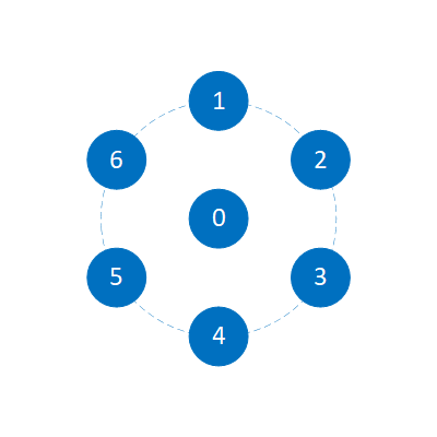 |
6 Outer, 1 Center, Radius = 42.5 mm, Evenly Spaced |
| Circular - 4 Microphones | 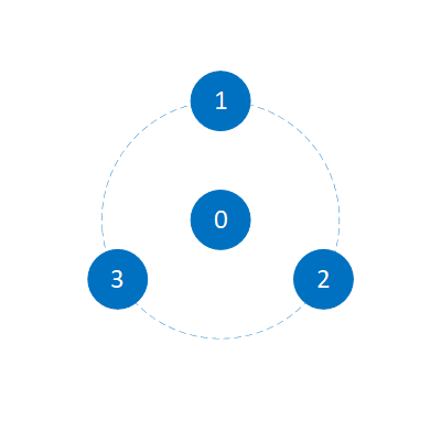 |
3 Outer, 1 Center, Radius = 42.5 mm, Evenly Spaced |
| Linear - 4 Microphones | 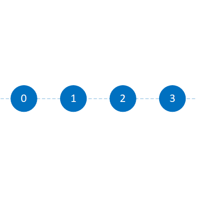 |
Length = 120 mm, Spacing = 40 mm |
| Linear - 2 Microphones | 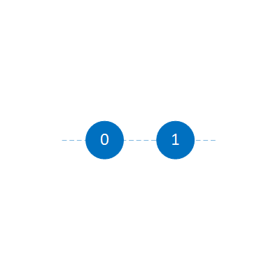 |
Spacing = 40 mm |
Microphone channels should be ordered ascending from 0, according to the numbering previously described for each array. The Microsoft Audio Stack requires another reference stream of audio playback to perform echo cancellation.
Component selection
Microphone components should be selected to accurately reproduce a signal free of noise and distortion.
The recommended properties when selecting microphones are:
| Parameter | Recommended |
|---|---|
| SNR | >= 65 dB (1 kHz signal 94 dBSPL, A-weighted noise) |
| Amplitude Matching | ± 1 dB @ 1 kHz |
| Phase Matching | ± 2° @ 1 kHz |
| Acoustic Overload Point (AOP) | >= 120 dBSPL (THD = 10%) |
| Bit Rate | Minimum 24-bit |
| Sampling Rate | Minimum 16 kHz* |
| Frequency Response | ± 3 dB, 200-8000 Hz Floating Mask* |
| Reliability | Storage Temperature Range -40°C to 70°C Operating Temperature Range -20°C to 55°C |
*Higher sampling rates or "wider" frequency ranges might be necessary for high-quality communications (VoIP) applications
Good component selection must be paired with good electroacoustic integration in order to avoid impairing the performance of the components used. Unique use cases might also necessitate more requirements (such as operating temperature ranges).
Microphone array integration
The performance of the microphone array when integrated into a device differs from the component specification. It's important to ensure that the microphones are well matched after integration. Therefore the device performance measured after any fixed gain or EQ should meet the following recommendations:
| Parameter | Recommended |
|---|---|
| SNR | >= 64 dB (1 kHz signal 94 dBSPL, A-weighted noise) |
| Output Sensitivity | -26 dBFS/Pa @ 1 kHz (recommended) |
| Amplitude Matching | ± 2 dB, 200-8000 Hz |
| THD%* | ≤ 1%, 200-8000 Hz, 94 dBSPL |
| Frequency Response | ± 6 dB, 200-12000 Hz Floating Mask** |
**A low distortion speaker is required to measure THD (for example, Neumann KH120)
**"Wider" frequency ranges might be necessary for high-quality communications (VoIP) applications
Speaker integration recommendations
As echo cancellation is necessary for speech recognition devices that contain speakers, more recommendations are provided for speaker selection and integration.
| Parameter | Recommended |
|---|---|
| Linearity Considerations | No nonlinear processing after speaker reference, otherwise a hardware-based loopback reference stream is required |
| Speaker Loopback | Provided via WASAPI, private APIs, custom ALSA plug-in (Linux), or provided via firmware channel |
| THD% | Third Octave Bands minimum fifth Order, 70 dBA Playback @ 0.8 m ≤ 6.3%, 315-500 Hz ≤ 5%, 630-5000 Hz |
| Echo Coupling to Microphones | > -10 dB TCLw using ITU-T G.122 Annex B.4 method, normalized to mic level TCLw = TCLwmeasured + (Measured Level - Target Output Sensitivity) TCLw = TCLwmeasured + (Measured Level - (-26)) |
Integration design architecture
The following guidelines for architecture are necessary when integrating microphones into a device:
| Parameter | Recommendation |
|---|---|
| Mic Port Similarity | All microphone ports are same length in array |
| Mic Port Dimensions | Port size Ø0.8-1.0 mm. Port Length / Port Diameter < 2 |
| Mic Sealing | Sealing gaskets uniformly implemented in stack-up. Recommend > 70% compression ratio for foam gaskets |
| Mic Reliability | Mesh should be used to prevent dust and ingress (between PCB for bottom ported microphones and sealing gasket/top cover) |
| Mic Isolation | Rubber gaskets and vibration decoupling through structure, particularly for isolating any vibration paths due to integrated speakers |
| Sampling Clock | Device audio must be free of jitter and drop-outs with low drift |
| Record Capability | The device must be able to record individual channel raw streams simultaneously |
| USB | All USB audio input devices must set descriptors according to the USB Audio Devices Rev3 Spec |
| Microphone Geometry | Drivers must implement Microphone Array Geometry Descriptors correctly |
| Discoverability | Devices must not have any undiscoverable or uncontrollable hardware, firmware, or third party software-based nonlinear audio processing algorithms to/from the device |
| Capture Format | Capture formats must use a minimum sampling rate of 16 kHz and recommended 24-bit depth |
Electrical architecture considerations
Where applicable, arrays can be connected to a USB host (such as a SoC that runs the Microsoft Audio Stack (MAS)) and interfaces to Speech services or other applications.
Hardware components such as PDM-to-TDM conversion should ensure that the dynamic range and SNR of the microphones is preserved within re-samplers.
High-speed USB Audio Class 2.0 should be supported within any audio MCUs in order to provide the necessary bandwidth for up to seven channels at higher sample rates and bit depths.
Next steps
Povratne informacije
Uskoro: tokom 2024. postepeno ćemo ukidati probleme s uslugom GitHub kao mehanizam povratnih informacija za sadržaj i zamijeniti ga novim sistemom povratnih informacija. Za više informacija, pogledajte https://aka.ms/ContentUserFeedback.
Pošalјite i prikažite povratne informacije za