Azure IoT Edge for Linux on Windows virtual switch creation
Applies to: ![]() IoT Edge 1.4
IoT Edge 1.4
Important
IoT Edge 1.4 is the supported release. If you are on an earlier release, see Update IoT Edge.
Azure IoT Edge for Linux on Windows uses a virtual switch on the host machine to communicate with the virtual machine. Windows desktop versions come with a default switch that can be used, but Windows Server doesn't. Before you can deploy IoT Edge for Linux on Windows to a Windows Server device, you need to create a virtual switch. Furthermore, you can use this guide to create your custom virtual switch, if needed.
This article shows you how to create a virtual switch on a Windows device to install IoT Edge for Linux on Windows. This process is divided into the following steps:
- Create a virtual switch
- Create a NAT table
- Install and set up a DHCP server
Prerequisites
- A Windows device. For more information on supported Windows versions, see Operating Systems.
- Hyper-V role installed on the Windows device. For more information on how to enable Hyper-V, see Install and provision Azure IoT Edge for Linux on a Windows device.
Create virtual switch
The following steps in this section are a generic guide for a virtual switch creation. Ensure that the virtual switch configuration aligns with your networking environment.
Note
The following steps describe how to create an Internal or Private virtual switch. For more information on creating an External switch instead, see Create a virtual switch for Hyper-V virtual machines. Note that if you're using an Azure VM, the virtual switch can't be External.
Open PowerShell in an elevated session. You can do so by opening the Start pane on Windows and typing in "PowerShell". Right-click the Windows PowerShell app that shows up and select Run as administrator.
Check the virtual switches on the Windows host and make sure you don't already have a virtual switch that can be used. You can do so by running the following Get-VMSwitch command in PowerShell:
Get-VMSwitchIf a virtual switch named Default Switch is already created and you don't need a custom virtual switch, you should be able to install IoT Edge for Linux on Windows without following the rest of the steps in this guide.
Create a new VM switch with a name of your choice and an Internal or Private switch type by running the following New-VMSwitch command, replacing the placeholder values:
New-VMSwitch -Name "{switchName}" -SwitchType {switchType}To get the IP address for the switch you created, you must first get its interface index. You can get this value by running the following Get-NetAdapter command, replacing the placeholder value:
(Get-NetAdapter -Name "{switchName}").ifIndexYou may need to change the value for the
Nameparameter to follow thevEthernet ({switchName})template if you receive an error when you try to run this command. You should receive similar output to the following example: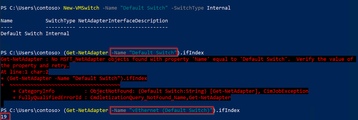
Take note of the interface index value, as you'll need to use it in future steps.
The resulting virtual switch IP address will be different for each environment. Note that for the rest of the commands in this guide you will make use of IP addresses that are derived from the 172.20.X.Y family. However, you can you use your own address family and IP addresses.
You'll create and use the following IP addresses:
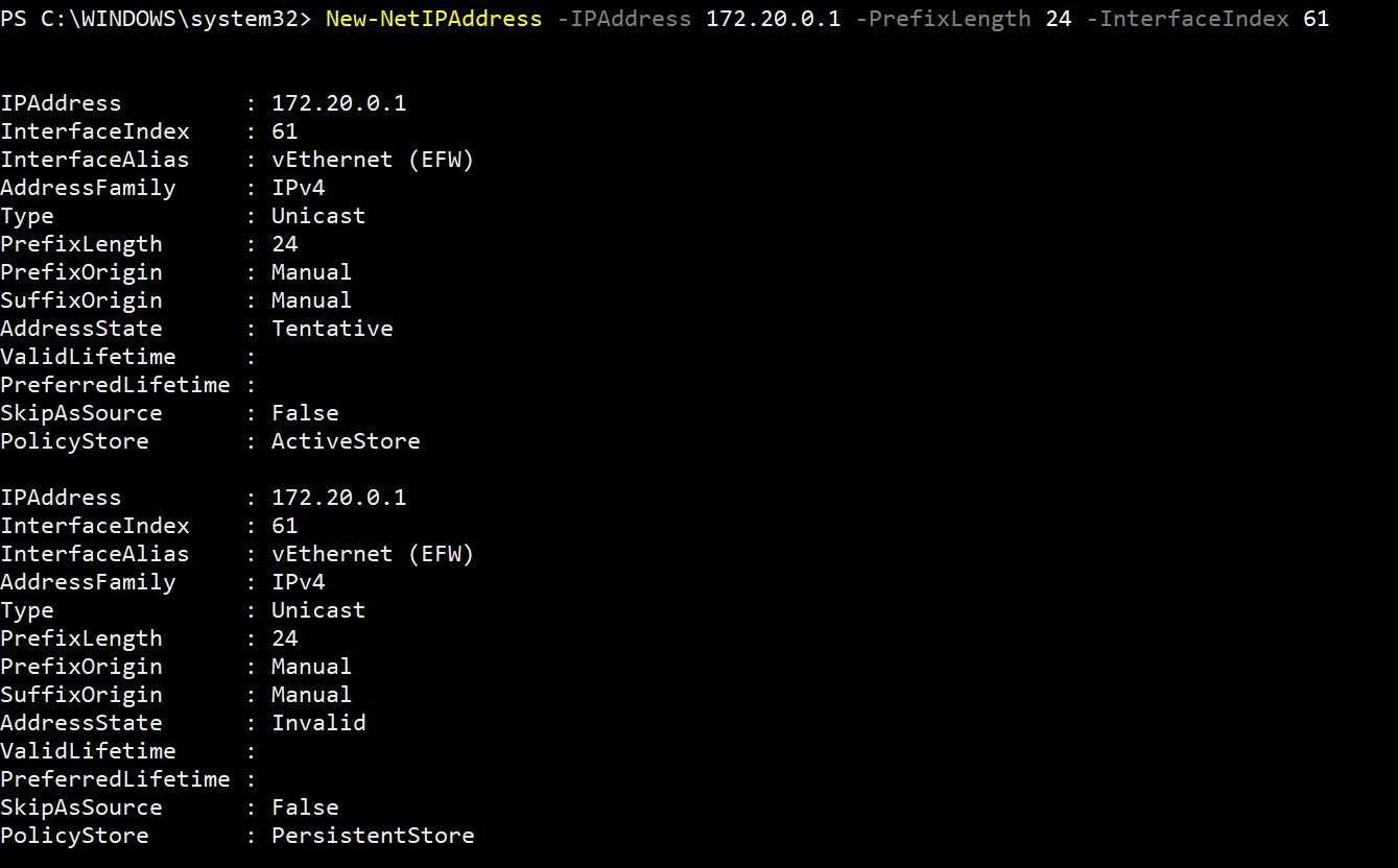
IP address Template Example Gateway IP xxx.xxx.xxx.1 172.20.0.1 NAT IP xxx.xxx.xxx.0 172.20.0.0 Start IP xxx.xxx.xxx.100 172.20.0.100 End IP xxx.xxx.xxx.200 172.20.0.200 Set the gateway IP address by replacing the last octet of your virtual switch IP address family with a new numerical value. For example, replace last octet with 1 and get the address 172.20.0.1. Run the following New-NetIPAddress command to set the new gateway IP address, replacing the placeholder values:
New-NetIPAddress -IPAddress {gatewayIp} -PrefixLength 24 -InterfaceIndex {interfaceIndex}Running this command should output information similar to the following example:
Create a Network Address Translation (NAT) object that translates an internal network address to an external network. Use the same IPv4 family address from previous steps. Based on the table from step six, the NAT IP address corresponds to the original IP address family, except that the last octet is replaced with a new numerical value, for example 0. Run the following New-NetNat command to set the NAT IP address, replacing the placeholder values:
New-NetNat -Name "{switchName}" -InternalIPInterfaceAddressPrefix "{natIp}/24"Running this command should output information similar to the following example:


The switch is now created. Next, you'll set up the DNS.
Create DHCP Server
Note
It is possible to continue the installation without a DHCP server as long as the EFLOW VM is deployed using Static IP parameters (ip4Address, ip4GatewayAddress, ip4PrefixLength). If dynamic IP allocation will be used, ensure to continue with the DHCP server installation.
Warning
Authorization might be required to deploy a DHCP server in a corporate network environment. Check if the virtual switch configuration complies with your corporate network's policies. For more information, see Deploy DHCP Using Windows PowerShell.
Check if the DHCP Server feature is installed on the host machine. Look for the Install State column. If the value is "Installed", you can skip the following step.
Get-WindowsFeature -Name 'DHCP'If the DHCP server isn't already installed, do so by running the following command:
Install-WindowsFeature -Name 'DHCP' -IncludeManagementToolsAdd the DHCP Server to the default local security groups and restart the server.
netsh dhcp add securitygroups
Restart-Service dhcpserver
You'll receive the following warning messages while the DHCP server is starting up:
WARNING: Waiting for service 'DHCP Server (dhcpserver)' to start...To configure the DHCP server range of IPs to be made available, you'll need to set an IP address as the start IP and an IP address as the end IP. This range is defined by the StartRange and the EndRange parameters in the Add-DhcpServerv4Scope command. You'll also need to set the subnet mask when running this command, which will be 255.255.255.0. Based on the IP address templates and examples in the table from the previous section, setting the StartRange as 169.254.229.100 and the EndRange as 169.254.229.200 will make 100 IP addresses available. Run the following command, replacing the placeholders with your own values:
Add-DhcpServerV4Scope -Name "AzureIoTEdgeScope" -StartRange {startIp} -EndRange {endIp} -SubnetMask 255.255.255.0 -State ActiveThis command should produce no output.
Assign the NAT and gateway IP addresses you created in the earlier section to the DHCP server, and restart the server to load the configuration. The first command should produce no output, but restarting the DHCP server should output the same warning messages that you received when you did so in the third step of this section.
Set-DhcpServerV4OptionValue -ScopeID {startIp} -Router {gatewayIp}
Restart-service dhcpserver
Next steps
Follow the steps in Install and provision Azure IoT Edge for Linux on a Windows device to set up a device with IoT Edge for Linux on Windows.
Feedback
Coming soon: Throughout 2024 we will be phasing out GitHub Issues as the feedback mechanism for content and replacing it with a new feedback system. For more information see: https://aka.ms/ContentUserFeedback.
Submit and view feedback for