Private mobile network design requirements
This article helps you design and prepare for implementing a private 4G, or 5G network based on Azure Private 5G Core (AP5GC). It aims to provide an understanding of how these networks are constructed and the decisions that you need to make as you plan your network.
Azure Private MEC and Azure Private 5G Core
Azure private multi-access edge compute (MEC) is a solution that combines Microsoft compute, networking, and application services into a deployment at enterprise premises (the edge). These edge deployments are managed centrally from the cloud. Azure Private 5G Core is an Azure service within Azure Private Multi-access Edge Compute (MEC) that provides 4G and 5G core network functions at the enterprise edge. At the enterprise edge site, devices attach across a cellular radio access network (RAN) and are connected via the Azure Private 5G Core service to upstream networks, applications, and resources. Optionally, devices might use the local compute capability provided by Azure Private MEC to process data streams at very low latency, all under the control of the enterprise.
Requirements for a private mobile network
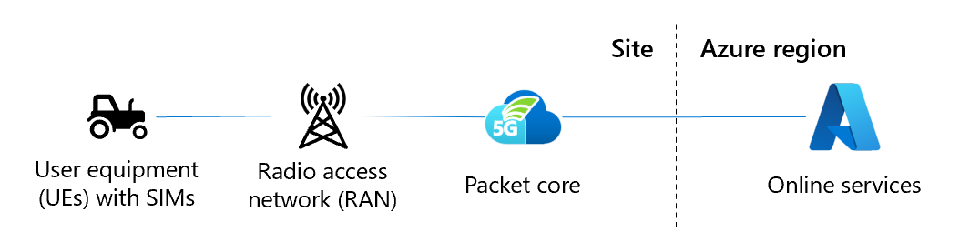
The following capabilities must be present to allow user equipment (UEs) to attach to a private cellular network:
- The UE must be compatible with the protocol and the wireless spectrum band used by the radio access network (RAN).
- The UE must contain a subscriber identity module (SIM). The SIM is a cryptographic element that stores the identity of the device.
- There must be a RAN, sending and receiving the cellular signal, to all parts of the enterprise site that contain UEs needing service.
- There must be a packet core instance connected to the RAN and to an upstream network. The packet core is responsible for authenticating the UE's SIMs as they connect across the RAN and request service from the network. It applies policy to the resulting data flows to and from the UEs; for example, to set a quality of service.
- The RAN, packet core, and upstream network infrastructure must be connected via Ethernet so that they can pass IP traffic to one another.
- The site hosting the packet core must have a continuous, high speed connection to the internet (100 Mbps minimum) to allow for service management, telemetry, diagnostics, and upgrades.
Designing a private mobile network
The following sections describe elements of the network you need to consider and the design decisions you need to make in preparation for deploying the network.
Topology
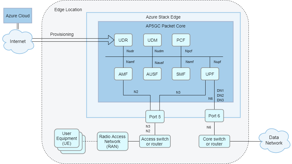
Designing and implementing your local network is a foundational part of your AP5GC deployment. You need to make networking design decisions to support your AP5GC packet core and any other edge workloads. This section outlines some decisions you should consider when designing your network and provides some sample network topologies. The following diagram shows a basic network topology.

Design considerations
When deployed on Azure Stack Edge Pro GPU (ASE), AP5GC uses physical port 5 for access signaling and data (5G N2 and N3 reference points/4G S1 and S1-U reference points) and port 6 for core data (5G N6/4G SGi reference points). If more than six data networks are configured, port 5 is also used for core data.
AP5GC supports deployments with or without layer 3 routers on ports 5 and 6. This is useful for avoiding extra hardware at smaller edge sites.
- It is possible to connect ASE port 5 to RAN nodes directly (back-to-back) or via a layer 2 switch. When using this topology, you must configure the eNodeB/gNodeB address as the default gateway on the ASE network interface.
- Similarly, it is possible to connect ASE port 6 to your core network via a layer 2 switch. When using this topology, you must set up an application or an arbitrary address on the subnet as gateway on the ASE side.
- Alternatively, you can combine these approaches. For example, you could use a router on ASE port 6 with a flat layer 2 network on ASE port 5. If a layer 3 router is present in the local network, you must configure it to match the ASE's configuration.
When deployed on Azure Stack Edge 2 (ASE 2), AP5GC uses physical port 3 for access signaling and data (5G N2 and N3 reference points/4G S1 and S1-U reference points) and port 4 for core data (5G N6/4G SGi reference points). If more than six data networks are configured, port 3 is also used for core data.
AP5GC supports deployments with or without layer 3 routers on ports 3 and 4. This is useful for avoiding extra hardware at smaller edge sites.
- It is possible to connect ASE port 3 to RAN nodes directly (back-to-back) or via a layer 2 switch. When using this topology, you must configure the eNodeB/gNodeB address as the default gateway on the ASE network interface.
- Similarly, it is possible to connect ASE port 4 to your core network via a layer 2 switch. When using this topology, you must set up an application or an arbitrary address on the subnet as gateway on the ASE side.
- Alternatively, you can combine these approaches. For example, you could use a router on ASE port 4 with a flat layer 2 network on ASE port 3. If a layer 3 router is present in the local network, you must configure it to match the ASE's configuration.
Unless your packet core has Network Address Translation (NAT) enabled, a local layer 3 network device must be configured with static routes to the UE IP pools via the appropriate N6 IP address for the corresponding attached data network.
Sample network topologies
There are multiple ways to set up your network for use with AP5GC. The exact setup varies depending on your needs and hardware. This section provides some sample network topologies on ASE Pro GPU hardware.
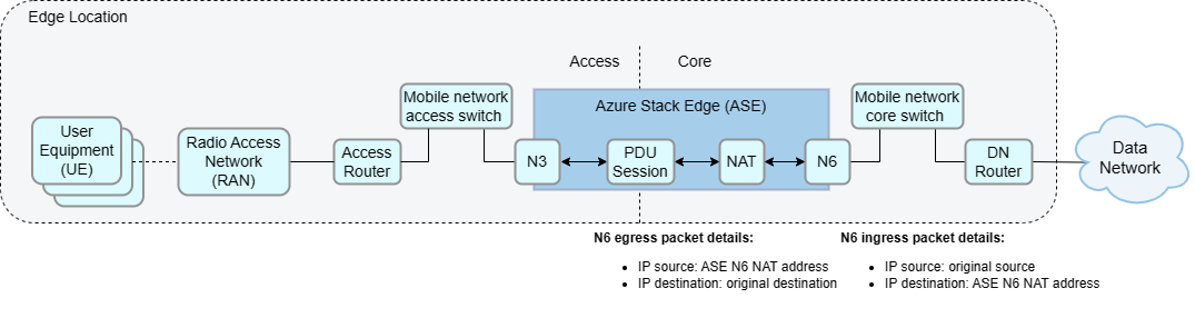
Layer 3 network with N6 Network Address Translation (NAT)
This network topology has your ASE connected to a layer 2 device that provides connectivity to the mobile network core and access gateways (routers connecting your ASE to your data and access networks respectively). This topology supports up to six data networks. This solution is commonly used because it simplifies layer 3 routing.
Layer 3 network without Network Address Translation (NAT)
This network topology is a similar solution, but UE IP address ranges must be configured as static routes in the data network router with the N6 NAT IP address as the next hop address. As with the previous solution, this topology supports up to six data networks.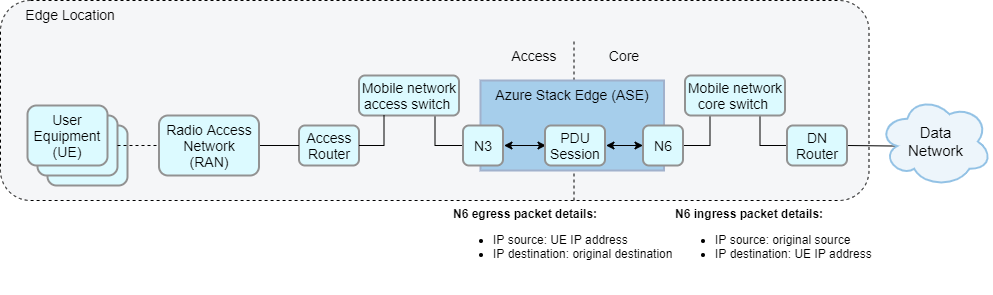
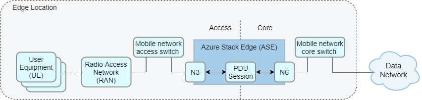
Flat layer 2 network
The packet core does not require layer 3 routers or any router-like functionality. An alternative topology could forgo the use of layer 3 gateway routers entirely and instead construct a layer 2 network in which the ASE is in the same subnet as the data and access networks. This network topology can be a cheaper alternative when you don’t require layer 3 routing. This requires Network Address Port Translation (NAPT) to be enabled on the packet core.
Layer 3 network with multiple data networks
- AP5GC can support up to ten attached data networks, each with its own configuration for Domain Name System (DNS), UE IP address pools, N6 IP configuration, and NAT. The operator can provision UEs as subscribed in one or more data networks and apply data network-specific policy and quality of service (QoS) configuration.
- This topology requires that the N6 interface is split into one subnet for each data network or one subnet for all data networks. This option therefore requires careful planning and configuration to prevent overlapping data network IP ranges or UE IP ranges.
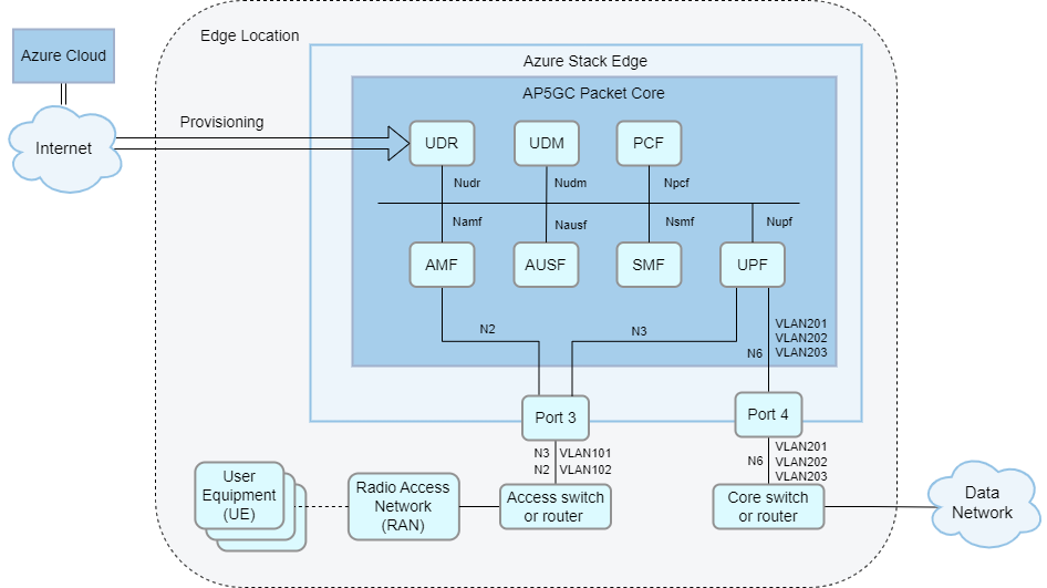
Layer 3 network with VLAN and physical access/core separation
- You can also separate ASE traffic into VLANs, whether or not you choose to add layer 3 gateways to your network. There are multiple benefits to segmenting traffic into separate VLANs, including more flexible network management and increased security.
- For example, you could configure separate VLANs for management, access and data traffic, or a separate VLAN for each attached data network.
- VLANs must be configured on the local layer 2 or layer 3 network equipment. Multiple VLANs will be carried on a single link from ASE port 5 (access network) and/or 6 (core network), so you must configure each of those links as a VLAN trunk.

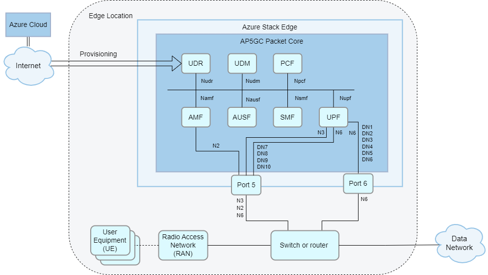
Layer 3 network with 7-10 data networks
- If you want to deploy more than six VLAN-separated data networks, the additional (up to four) data networks must be deployed on ASE port 5. This requires one shared switch or router that carries both access and core traffic. VLAN tags can be assigned as required to N2, N3 and each of the N6 data networks.
- No more than six data networks can be configured on the same port.
- For optimal performance, the data networks with the highest expected load should be configured on port 6.


There are multiple ways to set up your network for use with AP5GC. The exact setup varies depending on your needs and hardware. This section provides some sample network topologies on ASE Pro 2 hardware.
Layer 3 network with N6 Network Address Translation (NAT)
This network topology has your ASE connected to a layer 2 device that provides connectivity to the mobile network core and access gateways (routers connecting your ASE to your data and access networks respectively). This topology supports up to six data networks. This solution is commonly used because it simplifies layer 3 routing.
Layer 3 network without Network Address Translation (NAT)
This network topology is a similar solution, but UE IP address ranges must be configured as static routes in the data network router with the N6 NAT IP address as the next hop address. As with the previous solution, this topology supports up to six data networks.
Flat layer 2 network
The packet core does not require layer 3 routers or any router-like functionality. An alternative topology could forgo the use of layer 3 gateway routers entirely and instead construct a layer 2 network in which the ASE is in the same subnet as the data and access networks. This network topology can be a cheaper alternative when you don’t require layer 3 routing. This requires Network Address Port Translation (NAPT) to be enabled on the packet core.
Layer 3 network with multiple data networks
- AP5GC can support up to ten attached data networks, each with its own configuration for Domain Name System (DNS), UE IP address pools, N6 IP configuration, and NAT. The operator can provision UEs as subscribed in one or more data networks and apply data network-specific policy and quality of service (QoS) configuration.
- This topology requires that the N6 interface is split into one subnet for each data network or one subnet for all data networks. This option therefore requires careful planning and configuration to prevent overlapping data network IP ranges or UE IP ranges.

Layer 3 network with VLAN and physical access/core separation
- You can also separate ASE traffic into VLANs, whether or not you choose to add layer 3 gateways to your network. There are multiple benefits to segmenting traffic into separate VLANs, including more flexible network management and increased security.
- For example, you could configure separate VLANs for management, access and data traffic, or a separate VLAN for each attached data network.
- VLANs must be configured on the local layer 2 or layer 3 network equipment. Multiple VLANs will be carried on a single link from ASE port 3 (access network) and/or 4 (core network), so you must configure each of those links as a VLAN trunk.
Layer 3 network with 7-10 data networks
- If you want to deploy more than six VLAN-separated data networks, the additional (up to four) data networks must be deployed on ASE port 3. This requires one shared switch or router that carries both access and core traffic. VLAN tags can be assigned as required to N2, N3 and each of the N6 data networks.
- No more than six data networks can be configured on the same port.
- For optimal performance, the data networks with the highest expected load should be configured on port 4.


Subnets and IP addresses
You might have existing IP networks at the enterprise site that the private cellular network will have to integrate with. This might mean, for example:
- Selecting IP subnets and IP addresses for AP5GC that match existing subnets without clashing addresses.
- Segregating the new network via IP routers or using the private RFC 1918 address space for subnets.
- Assigning a pool of IP addresses specifically for use by UEs when they attach to the network.
- Using Network Address Port Translation (NAPT), either on the packet core itself or on an upstream network device such as a border router.
- Optimizing the network for performance by choosing a maximum transmission unit (MTU) that minimizes fragmentation.
You need to document the IPv4 subnets that will be used for the deployment and agree on the IP addresses to use for each element in the solution, and on the IP addresses that will be allocated to UEs when they attach. You need to deploy (or configure existing) routers and firewalls at the enterprise site to permit traffic. You should also agree how and where in the network any NAPT or MTU changes are required and plan the associated router/firewall configuration. For more information, see Complete the prerequisite tasks for deploying a private mobile network.
Network access
Your design must reflect the enterprise’s rules on what networks and assets should be reachable by the RAN and UEs on the private 5G network. For example, they might be permitted to access local Domain Name System (DNS), Dynamic Host Configuration Protocol (DHCP), the internet, or Azure, but not a factory operations local area network (LAN). You might need to arrange for remote access to the network so that you can troubleshoot issues without requiring a site visit. You also need to consider how the enterprise site will be connected to upstream networks such as Azure for management and/or for access to other resources and applications outside of the enterprise site.
You need to agree with the enterprise team which IP subnets and addresses will be allowed to communicate with each other. Then, create a routing plan and/or access control list (ACL) configuration that implements this agreement on the local IP infrastructure. You might also use virtual local area networks (VLANs) to partition elements at layer 2, configuring your switch fabric to assign connected ports to specific VLANs (for example, to put the Azure Stack Edge port used for RAN access into the same VLAN as the RAN units connected to the Ethernet switch). You should also agree with the enterprise to set up an access mechanism, such as a virtual private network (VPN), that allows your support personnel to remotely connect to the management interface of each element in the solution. You also need an IP link between Azure Private 5G Core and Azure for management and telemetry.
RAN compliance
The RAN that you use to broadcast the signal across the enterprise site must comply with local regulations. For example, this could mean:
- The RAN units have completed the process of homologation and received regulatory approval for their use on a certain frequency band in a country/region.
- You have received permission for the RAN to broadcast using spectrum in a certain location, for example, by grant from a telecom operator, regulatory authority or via a technological solution such as a Spectrum Access System (SAS).
- The RAN units in a site have access to high-precision timing sources, such as Precision Time Protocol (PTP) and GPS location services.
You should ask your RAN partner for the countries/regions and frequency bands for which the RAN is approved. You might find that you need to use multiple RAN partners to cover the countries and regions in which you provide your solution. Although the RAN, UE and packet core all communicate using standard protocols, we recommend that you perform interoperability testing for the specific 4G Long-Term Evolution (LTE) or 5G standalone (SA) protocol between Azure Private 5G Core, UEs and the RAN prior to any deployment at an enterprise customer.
Your RAN will transmit a Public Land Mobile Network Identity (PLMN ID) to all UEs on the frequency band it is configured to use. You should define the PLMN ID and confirm your access to spectrum. In some countries/regions, spectrum must be obtained from the national/regional regulator or incumbent telecommunications operator. For example, if you're using the band 48 Citizens Broadband Radio Service (CBRS) spectrum, you might need to work with your RAN partner to deploy a Spectrum Access System (SAS) domain proxy on the enterprise site so that the RAN can continuously check that it is authorized to broadcast.
Maximum Transmission Units (MTUs)
The Maximum Transmission Unit (MTU) is a property of an IP link, and it is configured on the interfaces at each end of the link. Packets that exceed an interface's configured MTU are split into smaller packets via IPv4 fragmentation prior to sending and are then reassembled at their destination. However, if an interface's configured MTU is higher than the link's supported MTU, the packet will fail to be transmitted correctly.
To avoid transmission issues caused by IPv4 fragmentation, a 4G, or 5G packet core instructs UEs what MTU they should use. However, UEs do not always respect the MTU signaled by the packet core.
IP packets from UEs are tunneled through from the RAN, which adds overhead from encapsulation. The MTU value for the UE should therefore be smaller than the MTU value used between the RAN and the packet core to avoid transmission issues.
RANs typically come pre-configured with an MTU of 1500. The packet core’s default UE MTU is 1440 bytes to allow for encapsulation overhead. These values maximize RAN interoperability, but risk that certain UEs will not observe the default MTU and will generate larger packets that require IPv4 fragmentation and that might be dropped by the network. If you are affected by this issue, it is strongly recommended to configure the RAN to use an MTU of 1560 or higher, which allows a sufficient overhead for the encapsulation and avoids fragmentation with a UE using a standard MTU of 1500.
You can also change the UE MTU signaled by the packet core. We recommend setting the MTU to a value within the range supported by your UEs and 60 bytes below the MTU signaled by the RAN. Note that:
- The data network (N6) is automatically updated to match the UE MTU.
- The access network (N3) is automatically updated to match the UE MTU plus 60.
- You can configure a value between 1280 and 1930 bytes.
To change the UE MTU signaled by the packet core, see Modify a packet core instance.
Signal coverage
The UEs must be able to communicate with the RAN from any location at the site. This means that the signals must propagate effectively in the environment, including accounting for obstructions and equipment, to support UEs moving around the site (for example, between indoor and outdoor areas).
You should perform a site survey with your RAN partner and the enterprise to make sure that the coverage is adequate. Make sure that you understand the RAN units’ capabilities in different environments and any limits (for example, on the number of attached UEs that a single unit can support). If your UEs are going to move around the site, you should also confirm that the RAN supports X2 (4G) or Xn (5G) handover, which allows for the UE to transition seamlessly between the coverage provided by two RAN units. If the RAN doesn't support X2 (4G) or Xn (5G), then RAN must support S1 (4G) and N2 (5G) for UE mobility. Note that UEs cannot use these handover techniques to roam between a private enterprise network and the public cellular network offered by a telecommunications operator.
SIMs
Every UE must present an identity to the network, encoded in a subscriber identity module (SIM). SIMs are available in different physical form factors and in software-only format (eSIM). The data encoded on the SIM must match the configuration of the RAN and of the provisioned identity data in Azure Private 5G Core.
Obtain SIMs in factors compatible with the UEs and programmed with the PLMN ID and keys that you want to use for the deployment. Physical SIMs are widely available on the open market at relatively low cost. If you prefer to use eSIMs, you need to deploy the necessary eSIM configuration and provisioning infrastructure so that UEs can configure themselves before they attach to the cellular network. You can use the provisioning data you receive from your SIM partner to provision matching entries in Azure Private 5G Core. Because SIM data must be kept secure, the cryptographic keys used to provision SIMs are not readable once set, so you must consider how you store them in case you ever need to reprovision the data in Azure Private 5G Core.
Automation and integration
Building enterprise networks using automation and other programmatic techniques saves time, reduces errors, and produces better outcomes. These techniques also provide a recovery path in the event of a site failure that requires rebuilding the network.
We recommend adopting a programmatic, infrastructure as code approach to your deployments. You can use templates or the Azure REST API to build your deployment using parameters as inputs with values that you have collected during the design phase of the project. You should save provisioning information such as SIM data, switch/router configuration, and network policies in machine-readable format so that, in the event of a failure, you can reapply the configuration in the same way as you originally did. Another best practice to recover from failure is to deploy a spare Azure Stack Edge server to minimize recovery time if the first unit fails; you can then use your saved templates and inputs to quickly recreate the deployment. For more information on deploying a network using templates, refer to Quickstart: Deploy a private mobile network and site - ARM template.
You must also consider how you integrate other Azure products and services with the private enterprise network. These products include Microsoft Entra ID and role-based access control (RBAC), where you must consider how tenants, subscriptions and resource permissions will align with the business model that exists between you and the enterprise, and as your own approach to customer system management. For example, you might use Azure Blueprints to set up the subscriptions and resource group model that works best for your organization.
Next steps
Feedback
Coming soon: Throughout 2024 we will be phasing out GitHub Issues as the feedback mechanism for content and replacing it with a new feedback system. For more information see: https://aka.ms/ContentUserFeedback.
Submit and view feedback for