Configure model conversion parameters
In this article, learn how to configure parameters for a model conversion.
Settings file
If a file called <modelName>.ConversionSettings.json is found in the input container beside the input model <modelName>.<ext>, then the file is used to provide extra configuration for the model conversion process. For example, when you convert box.gltf, you'd use box.ConversionSettings.json to set parameters for the model conversion.
The contents of the JSON conversion settings file should have this schema:
{
    "$schema" : "http://json-schema.org/schema#",
    "description" : "ARR ConversionSettings Schema",
    "type" : "object",
    "definitions" :
    {
        "position_attribute" : {"type" : "string", "description" : "Destination format of the position attribute", "enum" : [ "32_32_32_FLOAT", "16_16_16_16_FLOAT" ]},
        "color_attribute" : {"type" : "string", "description" : "Destination format of the color attribute", "enum" : [ "NONE", "8_8_8_8_UNSIGNED_NORMALIZED" ]},
        "vector_attribute" : {"type" : "string", "description" : "Destination format of the normals, tangents and binormals attributes", "enum" : [ "NONE", "8_8_8_8_SIGNED_NORMALIZED", "16_16_16_16_FLOAT" ]},
        "texcoord_attribute" : {"type" : "string", "description" : "Destination format of the texture coordinates attribute", "enum" : [ "NONE", "32_32_FLOAT", "16_16_FLOAT" ]}
    },
    "properties" :
    {
        "scaling" : { "type" : "number", "exclusiveMinimum" : 0, "default" : 1.0 },
        "recenterToOrigin" : { "type" : "boolean", "default" : false },
        "opaqueMaterialDefaultSidedness" : {" type" : "string", "enum" : [ "SingleSided", "DoubleSided" ], "default" : "DoubleSided" },
        "material-override" : { "type" : "string", "default" : "" },
        "gammaToLinearMaterial" : { "type" : "boolean", "default" : false },
        "gammaToLinearVertex" : { "type" : "boolean", "default" : false },
        "sceneGraphMode" : { "type" : "string", "enum" : [ "none", "static", "dynamic" ], "default" : "dynamic" },
        "generateCollisionMesh" : { "type" : "boolean", "default" : true },
        "unlitMaterials" : { "type" : "boolean", "default" : false },
        "deduplicateMaterials" : {"type" : "boolean", "default" : true },
        "fbxAssumeMetallic" : {"type" : "boolean", "default" : true },
        "axis" : {
            "type" : "array",
            "items" : {
                "type" : "string",
                "enum" : [ "default", "+x", "-x", "+y", "-y", "+z", "-z" ]
            },
            "minItems" : 3,
            "maxItems" : 3
        },
        "vertex" : {
            "type" : "object",
            "properties" : {
                "position" : { "$ref" : "#/definitions/position_attribute" },
                "color0" : { "$ref" : "#/definitions/color_attribute" },
                "color1" : { "$ref" : "#/definitions/color_attribute" },
                "normal" : { "$ref" : "#/definitions/vector_attribute" },
                "tangent" : { "$ref" : "#/definitions/vector_attribute" },
                "binormal" : { "$ref" : "#/definitions/vector_attribute" },
                "texcoord0" : { "$ref" : "#/definitions/texcoord_attribute" },
                "texcoord1" : { "$ref" : "#/definitions/texcoord_attribute" }
            },
            "additionalProperties" : false
        },
        "metadataKeys" : {
            "type" : "array",
            "items" : {
              "type" : "string"
            }
        }
    },
    "additionalProperties" : false
}
A box.ConversionSettings.json file might look like this example:
{
    "scaling" : 0.01,
    "recenterToOrigin" : true,
    "material-override" : "box_materials_override.json"
}
The schema for converting a triangular mesh and a point cloud is identical. However, a point cloud conversion uses a strict subset of features compared to a triangular mesh conversion.
Settings for a triangular mesh
When you convert a triangular mesh, like from an .fbx file, all parameters in the schema example shown in the preceding section affect the conversion outcome. The next sections give you a detailed explanation of the parameters.
Geometry parameters
scaling: This parameter scales a model uniformly. Scaling can be used to grow or shrink a model, for example, to display a building model on a table top. Scaling is also important when a model is defined in units other than meters because the rendering engine expects meters. For example, if a model is defined in centimeters, then applying a scale of 0.01 renders the model at the correct size. Some source data formats (for example, .fbx files) provide a unit scaling hint. In this case, the conversion implicitly scales the model to meter units. The implicit scaling that's provided by the source format is applied on top of thescalingparameter. The final scaling factor is applied to the geometry vertices and the local transforms of the scene graph nodes. The scaling for the root entity's transform remains unmodified.Important
Showcase and Quickstart might compensate for any conversion-time scaling because they each have a built-in auto-scaling feature. For more information, see the troubleshooting guide.
recenterToOrigin: This parameter states that a model should be converted so that its bounding box is centered at the origin. If a source model is displaced far from the origin, floating-point precision issues might cause rendering artifacts. Centering the model can help in this scenario.opaqueMaterialDefaultSidedness: The rendering engine assumes that opaque materials are double-sided. If that assumption isn't true of a particular model, this parameter should be set toSingleSided. For more information, see Single-sided rendering.
Material deduplication
deduplicateMaterials: This parameter enables or disables automatic deduplication of materials that share the same properties and textures. Deduplication happens after material overrides are processed. It's enabled by default.If a model has more than 65,535 materials even after deduplication, the service attempts to merge materials that have similar properties. As a last option, any materials that exceed the limit are replaced by a red error material.
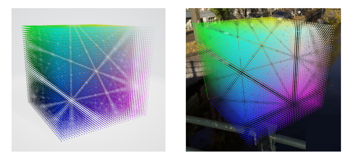
The following figure shows two cubes of 68,921 colored triangles. The left example is before deduplication, with 68,921 color materials. The right example is after deduplication, with 64,000 color materials. The limit is 65,535 materials. For more information about material limits, see limits.
Color space parameters
The rendering engine expects color values to be in linear space. If a model is defined by using gamma space, the following options should be set to true:
gammaToLinearMaterial: Convert material colors from gamma space to linear space.gammaToLinearVertex: Convert vertex colors from gamma space to linear space.
Note
For FBX, E57, PLY, LAS, LAZ, and XYZ file formats, these settings are set to true by default. For all other file formats, the default is false.
Scene parameters
sceneGraphMode: Defines how the scene graph in the source file is converted.dynamic(default): All objects in the file are exposed as entities in the API and can be transformed and reparented arbitrarily. At runtime, the node hierarchy is identical to the structure in the source file.static: Similar todynamic, but objects in the scene graph can't be reparented to other objects dynamically at runtime. For dynamic models that have many moving parts, such as the explosion view, thedynamicoption generates a model that is more efficient to render, butstaticmode still allows for individual part transforms. If dynamic reparenting isn't required, thestaticoption is the most suitable for models that have many individual parts.none: The scene graph is collapsed into one object.
Each mode has different runtime performance. In dynamic mode, the performance cost scales linearly with the number of entities in the graph, even when no part is moved. Use dynamic mode only when it's necessary to move many parts or large subgraphs simultaneously. An example is explosion view animation.
The static mode also exports the full scene graph. Spatial queries return individual parts, and each part can be modified through state overrides. With this mode, the runtime overhead per object is negligible. This mode is ideal for large scenes in which you need per-object inspection and occasional transform changes on individual parts, but no object reparenting.
The none mode has the least runtime overhead and also slightly better loading times. Inspection or transform of single objects isn't possible in this mode. Use cases are, for example, photogrammetry models that don't begin with a meaningful scene graph.
Tip
Many applications load multiple models. You should optimize the conversion parameters for each model depending on how you will use it. For example, if you want to display the model of a car for the user to take apart and inspect in detail, first convert it by using dynamic mode. However, if you also want to place the car in a show room environment, you can convert that model by using sceneGraphMode set to static, or even to none.
Physics parameters
generateCollisionMesh: If you need support for spatial queries on a model, this option must be enabled. Collision mesh generation doesn't add extra conversion time, and it also doesn't increase the output file size. The loading time and runtime cost of a model that has collision meshes is only insignificantly higher. You can leave this flag to the default (enabled) unless you have a specific reason to exclude a model from spatial queries.
Unlit materials
unlitMaterials: By default, the conversion creates physically based rendering (PBR) materials. When this option is set, the converter instead treats all materials as color materials. If you have data that already incorporates lighting, such as models created through photogrammetry, this option allows you to quickly enforce the correct conversion for all materials. You won't need to override each material individually.
Conversion from earlier FBX formats and Phong material models
fbxAssumeMetallic: Earlier versions of the FBX format define their materials by using a Phong material model. The conversion process must infer how these materials map to the renderer's PBR model. Usually this mapping works well, but an ambiguity can arise when a material has no textures, high specular values, and a non-grey albedo color. In this scenario, the conversion must choose between prioritizing the high specular values, defining a highly reflective and metallic material where the albedo color dissolves away, or prioritizing the albedo color by defining something, like in a shiny colorful plastic. By default, the conversion process assumes that highly specular values imply a metallic material in ambiguous scenarios. You can set this parameter tofalsefor the opposite effect.
Coordinate system override
axis: Use this parameter to override coordinate system unit vectors. Default values are["+x", "+y", "+z"]. In theory, the FBX format has a header in which those vectors are defined, and the conversion uses that information to transform the scene. The GLTF format also defines a fixed-coordinate system. In practice, some assets either have incorrect information in their header or were saved by using a different coordinate system convention. This option allows you to override the coordinate system to compensate. For example,"axis" : ["+x", "+z", "-y"]exchanges the Z-axis and the Y-axis and keeps coordinate system handedness by inverting the Y-axis direction.
Node metadata
metadataKeys: Use this parameter to specify keys of node metadata properties that you want to keep in the conversion result. You can specify exact keys or wildcard keys. Wildcard keys are of the formatABC*and match any key that starts withABC. Supported metadata value types arebool,int,float, andstring.For GLTF files, this data comes from the extras object on nodes. For FBX files, this data comes from the
Properties70data onModel nodes. For more information, see the documentation for your 3D Asset Tool.
When loading a model with meta data enabled, a specific entity's list of meta data entries can be retrieved through the asynchronous QueryMetadataAsync function.
Vertex format
It's possible to adjust the vertex format for a mesh to trade precision for memory savings. If your model has a lower memory footprint, you can load larger models or achieve better performance. However, depending on your data, the wrong format can significantly affect rendering quality.
Caution
Changing the vertex format should be a last option when models no longer fit into memory, or when you are optimizing for the best possible performance. Changes can easily introduce rendering artifacts, both obvious and subtle. Unless you know what to look out for, you should not change the default.
You can make these adjustments:
- Explicitly include or exclude specific data streams.
- Decrease the accuracy of data streams to reduce the memory footprint.
The following vertex section in the JSON file is optional. For each portion that isn't explicitly specified, the conversion service falls back to its default setting.
{
    ...
    "vertex" : {
        "position"  : "32_32_32_FLOAT",
        "color0"    : "NONE",
        "color1"    : "NONE",
        "normal"    : "NONE",
        "tangent"   : "NONE",
        "binormal"  : "NONE",
        "texcoord0" : "32_32_FLOAT",
        "texcoord1" : "NONE"
    },
    ...
}
By forcing a component to NONE, it's guaranteed that the output mesh doesn't have the respective stream.
Component formats per vertex stream
The following table describes formats that are allowed for respective components:
| Vertex component | Supported formats | Usage in materials |
|---|---|---|
position |
32_32_32_FLOAT (default), 16_16_16_16_FLOAT |
Vertex position. Must always be present. |
color0 |
8_8_8_8_UNSIGNED_NORMALIZED (default), NONE |
Vertex colors. See useVertexColor property both in color materials and PBR materials, and vertexMix in color materials. |
color1 |
8_8_8_8_UNSIGNED_NORMALIZED, NONE (default) |
Unused. Leave as default NONE. |
normal |
8_8_8_8_SIGNED_NORMALIZED (default), 16_16_16_16_FLOAT, NONE |
Used for lighting in PBR materials. |
tangent |
8_8_8_8_SIGNED_NORMALIZED (default), 16_16_16_16_FLOAT, NONE |
Used for lighting with normal maps in PBR materials. |
binormal |
8_8_8_8_SIGNED_NORMALIZED (default), 16_16_16_16_FLOAT, NONE |
Used for lighting with normal maps in PBR materials. |
texcoord0 |
32_32_FLOAT (default), 16_16_FLOAT, NONE |
First slot of texture coordinates. Individual textures like albedo and normal map can either use slot 0 or 1, which is defined in the source file. |
texcoord1 |
32_32_FLOAT (default), 16_16_FLOAT, NONE |
Second slot of texture coordinates. Individual textures like albedo and normal map can either use slot 0 or 1, which is defined in the source file. |
Supported component formats
The following table describes the memory footprints of supported component formats:
| Format | Description | Bytes per vertex |
|---|---|---|
32_32_FLOAT |
Two-component full floating-point precision | 8 |
16_16_FLOAT |
Two-component half floating-point precision | 4 |
32_32_32_FLOAT |
Three-component full floating-point precision | 12 |
16_16_16_16_FLOAT |
Four-component half floating-point precision | 8 |
8_8_8_8_UNSIGNED_NORMALIZED |
Four-component byte, normalized to the [0; 1] range |
4 |
8_8_8_8_SIGNED_NORMALIZED |
Four-component byte, normalized to the [-1; 1] range |
4 |
Best practices for component format changes
position: It's rare that reduced accuracy is sufficient.16_16_16_16_FLOATintroduces noticeable quantization artifacts, even for small models.normal,tangent, andbinormal: Typically, these values are changed together. Unless there are noticeable lighting artifacts that result from normal quantization, there's no reason to increase their accuracy. In some cases, though, these components can be set toNONE:normal,tangent, andbinormalare needed only when at least one material in the model should be lit. In Azure Remote Rendering, this scenario occurs when a PBR material is used on the model at any time.tangentandbinormalare needed only when any of the lit materials use a normal map texture.
texcoord0andtexcoord1: Texture coordinates can use reduced accuracy (16_16_FLOAT) when their values stay in the[0; 1]range and when the addressed textures have a maximum size of 2,048 × 2,048 pixels. If those limits are exceeded, the quality of texture mapping decreases.
Example
Assume you have a photogrammetry model, which has lighting baked into the textures. All that is needed to render the model are vertex positions and texture coordinates.
By default, the converter has to assume that you might want to use PBR materials on a model at some time, so it generates normal, tangent, and binormal data for you. So, the per-vertex memory usage is position (12 bytes) + texcoord0 (8 bytes) + normal (4 bytes) + tangent (4 bytes) + binormal (4 bytes) = 32 bytes. Larger models of this type can easily have many millions of vertices, resulting in models that can take up multiple gigabytes of memory. Such large amounts of data affect performance, and you might even run out of memory.
Knowing that you never need dynamic lighting on the model, and knowing that all texture coordinates are in the [0; 1] range, you can set normal, tangent, and binormal to NONE, and set texcoord0 to half-precision (16_16_FLOAT), resulting in only 16 bytes per vertex. When the mesh data is cut in half, you can load larger models, and performance is potentially improved.
Settings for point clouds
When a point cloud is converted, only a small subset of properties from the schema is used. Other properties are ignored unless they're specified.
The properties that do have an effect on point cloud conversion are:
scaling: The same meaning as for triangular meshes.recenterToOrigin: The same meaning as for triangular meshes.axis: The same meaning as for triangular meshes. Default values are["+x", "+y", "+z"], but most point cloud data is rotated compared to the renderer's own coordinate system. To compensate, in most cases["+x", "+z", "-y"]fixes the rotation.gammaToLinearVertex: Similar to triangular meshes, this flag indicates whether point colors should be converted from gamma space to linear space. The default value for point cloud formats (E57, PLY, LAS, LAZ, and XYZ files) istrue.generateCollisionMesh: Similar to triangular meshes, to support spatial queries, you must enable this flag.
Memory optimizations
Memory consumption of loaded content might become a bottleneck on the rendering system. If the memory payload becomes too large, it might compromise rendering performance or cause the model to not load altogether. This paragraph discusses some important strategies to reduce the memory footprint.
Note
The following optimizations apply to triangular meshes. You can't optimize the output of point clouds by configuring conversion settings.
Instancing
In instancing, meshes are reused for parts that have distinct spatial transformations instead of each part referencing its own unique geometry. Instancing has a significant impact on memory footprint.
Example use cases for instancing are the screws in an engine model or chairs in an architectural model.
Note
Instancing can improve the memory consumption (and thus loading times) significantly, but the improvements on rendering performance are insignificant.
The conversion service respects instancing if parts are marked up accordingly in the source file. However, conversion doesn't perform extra, deep analysis of mesh data to identify reusable parts. The content creation tool and its export pipeline are the decisive criteria for proper instancing setup.
A simple way to test whether instancing information is preserved during conversion is to look at the output statistics. Specifically, check the numMeshPartsInstanced value. If the value for numMeshPartsInstanced is larger than zero, meshes are shared across instances.
Example: Instancing setup in 3ds Max
Autodesk 3ds Max has distinct object cloning modes called Copy, Instance, and Reference. The modes work differently for instancing in the exported .fbx file.
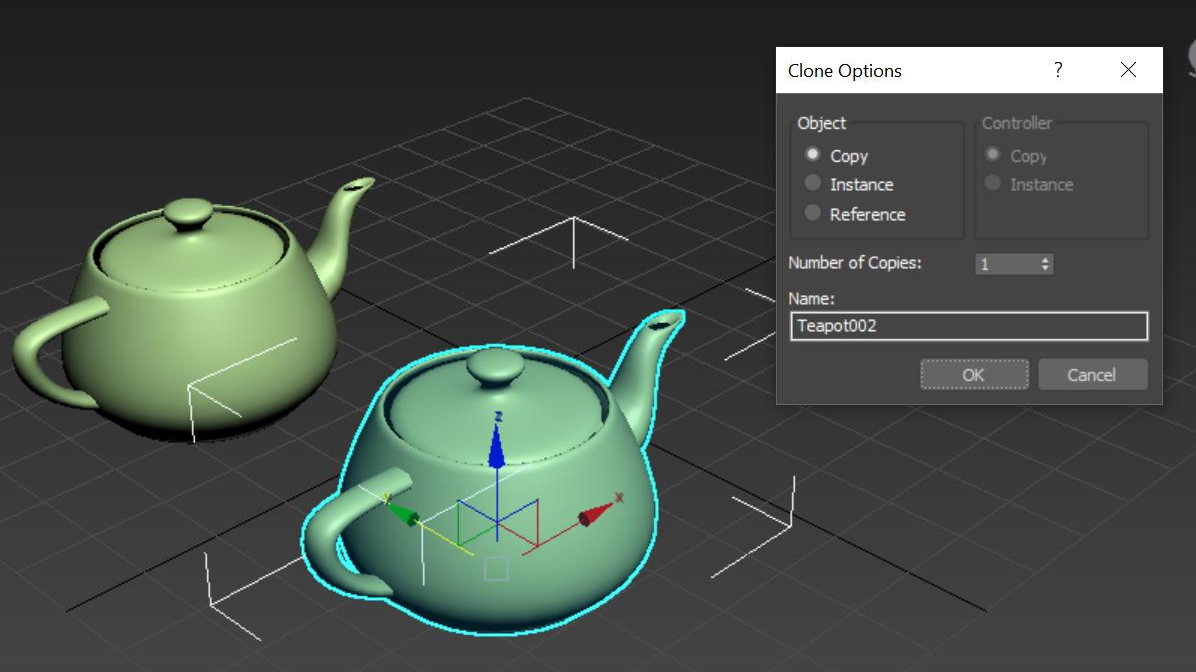
- Copy: In this mode, the mesh is cloned, so no instancing is used (
numMeshPartsInstanced=0). - Instance: The two objects share the same mesh, so instancing is used (
numMeshPartsInstanced=1). - Reference: Distinct modifiers can be applied to the geometries, so the exporter chooses a conservative approach and doesn't use instancing (
numMeshPartsInstanced=0).
Depth-based composition mode
If memory is a concern, configure the renderer by using the depth-based composition mode. In this mode, GPU payload is distributed across multiple GPUs.
Decrease vertex size
As discussed in Best practices for component format changes, adjusting the vertex format can decrease the memory footprint. However, this option should be the last option you choose.
Texture sizes
Depending on the type of scenario, the amount of texture data might outweigh the memory that's used for mesh data. Photogrammetry models are candidates. The conversion configuration doesn't provide a way to automatically scale down textures. If necessary, texture scaling must be done as a client-side preprocessing step. But the conversion step does choose a suitable texture compression format:
- BC1 file format for opaque color textures
- BC7 file format for source color textures with alpha channel
Because the BC7 file format has twice the memory footprint of the BC1 file format, it's important to make sure that the input textures don't provide an unnecessary alpha channel.
Typical use cases
Finding good import settings for a specific use case can be a tedious process. On the other hand, conversion settings might have a significant impact on runtime performance.
Some specific classes of use cases qualify for specific optimizations. Some examples are described in the following sections.
Use case: Architectural visualization or large outdoor maps
For scenarios that involve architectural visualization or large outdoor maps, consider the following factors:
These types of scenes tend to be static. They don't need movable parts. Accordingly, you can set
sceneGraphModetostatic, or even tonone, and improve runtime performance. Instaticmode, the scene's root node can still be moved, rotated, and scaled. For example, it can dynamically switch between 1:1 scale (for first-person view) and a table-top view.If the application doesn't use cut planes, the
opaqueMaterialDefaultSidednessflag should be turned off. The performance gain typically is 20 percent to 30 percent. You can still use cut planes, but there won't be a back-face when you look into the inner part of an object, which appears counterintuitive. For more information, see single-sided rendering.
Use case: Photogrammetry models
When you render photogrammetry models, you typically don't need a scene graph. In this scenario, you can choose to set sceneGraphMode to none. Because those models rarely contain a complex scene graph, the effect of choosing this option likely is insignificant. Because lighting is already baked into the textures, no dynamic lighting is needed. In this scenario:
- Set the
unlitMaterialsflag totrueto turn all materials into unlit color materials. - Remove unneeded data from the vertex format. See the earlier example.
Use case: Visualization of compact machines and others
In these use cases, the models often have a high degree of detail in a small volume. The renderer is heavily optimized to handle these cases well. However, most of the optimizations described in the earlier use case don't apply here. The optimizations include:
- Individual parts should be selectable and movable, so
sceneGraphModemust be set todynamic. - Ray casts are typically an integral part of the application, so collision meshes must be generated.
- Cut planes look better when the
opaqueMaterialDefaultSidednessflag is enabled.
Deprecated features
Setting model conversion parameters by using the non-model-specific conversionSettings.json filename is still supported, but it's deprecated. Instead, use the model-specific <modelName>.ConversionSettings.json filename.
Using a material-override setting to identify a material override file in the conversion settings file is still supported, but it's deprecated. Instead use the model-specific <modelName>.MaterialOverrides.json filename.
Next steps
Feedback
Coming soon: Throughout 2024 we will be phasing out GitHub Issues as the feedback mechanism for content and replacing it with a new feedback system. For more information see: https://aka.ms/ContentUserFeedback.
Submit and view feedback for