Set up an SDN RAS gateway in the VMM fabric
Important
This version of Virtual Machine Manager (VMM) has reached the end of support. We recommend you to upgrade to VMM 2022.
This article describes how to set up a Software Defined Networking (SDN) RAS gateway in the System Center - Virtual Machine Manager (VMM) fabric.
An SDN RAS gateway is a data path element in SDN that enables site-to-site connectivity between two autonomous systems. Specifically, a RAS gateway enables site-to-site connectivity between remote tenant networks and your datacenter using IPSec, Generic Routing Encapsulation (GRE), or Layer 3 Forwarding. Learn more.
Note
VMM 2022 provides dual stack support for RAS gateway.
Note
- From VMM 2019 UR1, One Connected network type is changed to Connected Network.
- VMM 2019 UR2 and later supports IPv6.
Before you start
Ensure the following before you start:
- Planning: Read about planning a software defined network, and review the planning topology in this document. The diagram shows a sample 4-node setup. The setup is highly available with Three network controller nodes (VM) and Three SLB/MUX nodes. It shows Two tenants with One virtual network broken into Two virtual subnets to simulate a web tier and a database tier. Both the infrastructure and tenant virtual machines can be redistributed across any physical host.
- Network controller: You should deploy the network controller before you deploy the RAS gateway.
- SLB: To ensure that dependencies are handled correctly, you should also deploy the SLB before setting up the gateway. If an SLB and a gateway are configured, you can use and validate an IPsec connection.
- Service template: VMM uses a service template to automate GW deployment. Service templates support multi-node deployment on generation 1 and generation 2 VMs.
Deployment steps
To set up a RAS gateway, do the following:
Download the service template: Download the service template that you need to deploy the GW.
Create the VIP logical network: Create a GRE VIP logical network. It needs an IP address pool for private VIPs and to assign VIPs to GRE endpoints. The network exists to define VIPs that are assigned to gateway VMs running on the SDN fabric for a site-to-site GRE connection.
Note
To enable dual stack support, while creating GRE VIP logical network, add IPv6 subnet to the network site and create IPv6 address pool. (applicable for 2022 and later)
Import the service template: Import the RAS gateway service template.
Deploy the gateway: Deploy a gateway service instance, and configure its properties.
Validate the deployment: Configure site-to-site GRE, IPSec, or L3, and validate the deployment.
Download the service template
- Download the SDN folder from the Microsoft SDN GitHub repository and copy the templates from VMM >Templates > GW to a local path on the VMM server.
- Extract the contents to a folder on a local computer. You'll import them to the library later.
The download contains Two templates:
- The EdgeServiceTemplate_Generation 1 VM.xml template is for deploying the GW Service on generation 1 virtual machines.
- The EdgeServiceTemplate_Generation 2 VM.xml is for deploying the GW Service on generation 2 virtual machines.
Both the templates have a default count of three virtual machines, which can be changed in the service template designer.
Create the GRE VIP logical network
- In the VMM console, run the Create Logical Network Wizard. Type a Name, optionally provide a description, and select Next.
- In Settings, select One Connected Network. Optionally, you can select Create a VM network with the same name. This setting allows VMs to access this logical network directly. Select Managed by the Network Controller, and select Next.
- For VMM 2019 UR1 and later, in Settings, select Connected Network, select Managed by the Network Controller, and then select Next.
- In Settings, select Connected Network, select Managed by the Network Controller, and then select Next.
In Network Site, specify the settings:
Here are the sample values:
- Network name: GRE VIP
- Subnet: 31.30.30.0
- Mask: 24
- VLAN ID on trunk: NA
- Gateway: 31.30.30.1
- In Summary, review the settings and finish the wizard.
To use IPv6, add both IPv4 and IPV6 subnet to the network site. Here are the sample values:
- Network name: GRE VIP
- Subnet: FD4A:293D:184F:382C::
- Mask: 64
- VLAN ID on trunk: NA
- Gateway: FD4A:293D:184F:382C::1
In Summary, review the settings and finish the wizard.
To use IPv4, add IPv4 subnet to the network site and create IPv4 address pool. Here are the sample values:
- Network name: GRE VIP
- Subnet:
- Mask:
- VLAN ID on trunk: NA
- Gateway:
To use IPv6, add both IPv4 and IPV6 subnets to the network site and create IPv6 address pool. Here are the sample values:
- Network name: GRE VIP
- Subnet: FD4A:293D:184F:382C::
- Mask: 64
- VLAN ID on trunk: NA
- Gateway: FD4A:293D:184F:382C::1
In Summary, review the settings and finish the wizard.
Create an IP address pool for GRE VIP addresses
Note
From VMM 2019 UR1 and later, you can create IP address pool using the Create Logical Network wizard.
Note
You can create an IP address pool using the Create Logical Network wizard.
- Right-click the GRE VIP logical network > Create IP Pool.
- Type a Name and optional description for the pool, and check that the VIP network is selected. Select Next.
- Accept the default network site and select Next.
- Choose a starting and ending IP address for your range. Start the range on the second address of your available subnet. For example, if your available subnet is from .1 to .254, start the range at .2.
- In the IP addresses reserved for load balancer VIPs box, type the IP addresses range in the subnet. This should match the range you used for starting and ending IP addresses.
- You don't need to provide gateway, DNS, or WINS information as this pool is used to allocate IP addresses for VIPs through the network controller only. Select Next to skip these screens.
- In Summary, review the settings and finish the wizard.
- If you had created IPv6 subnet, create a separate IPv6 GRE VIP address pool.
- Choose a starting and ending IP address for your range. Start the range on the second address of your available subnet. For example, if your available subnet is from .1 to .254, start the range at .2. For specifying VIP range, don’t use the shortened form of IPv6 address; Use the 2001:db8:0:200:0:0:0:7 format instead of 2001:db8:0:200::7.
- In the IP addresses reserved for load balancer VIPs box, type the IP addresses range in the subnet. This should match the range you used for starting and ending IP addresses.
- You don't need to provide gateway, DNS, or WINS information as this pool is used to allocate IP addresses for VIPs through the network controller only. Select Next to skip these screens.
- In Summary, review the settings and finish the wizard.
Import the service template
- Select Library > Import Template.
- Browse to your service template folder. As an example, select the EdgeServiceTemplate Generation 2.xml file.
- Update the parameters for your environment as you import the service template.
Note
The library resources were imported during the network controller deployment.
- WinServer.vhdx: Select the virtual hard drive image that you prepared and imported earlier during the network controller deployment.
- EdgeDeployment.CR: Map to the EdgeDeployment.cr library resource in the VMM library.
On the Summary page, review the details and select Import.
Note
You can customize the service template. Learn more.
Deploy the gateway service
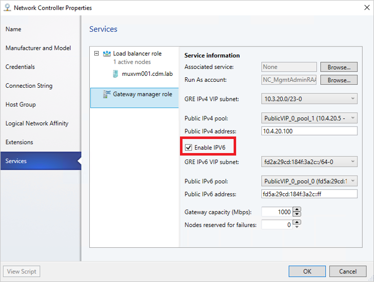
To enable IPv6, while onboarding Gateway service, select Enable IPv6 checkbox and select the IPv6 GRE VIP subnet that you've created previously. Also, select public IPv6 pool and provide the public IPv6 address.
This example uses the generation 2 template.
Select the EdgeServiceTemplate Generation2.xml service template, and select Configure Deployment.
Type a Name, and choose a destination for the service instance. The destination must map to a host group that contains the hosts configured previously for gateway deployment.
In Network Settings, map the management network to the management VM network.
Note
The Deploy Service dialog appears after the mapping is complete. It's normal for the VM instances to be initially Red. Select Refresh Preview to automatically find suitable hosts for the VM.
On the left of the Configure Deployment window, configure the following settings:
- AdminAccount. Required. Select a RunAs account that will be used as the local administrator on the gateway VMs.
- Management Network. Required. Choose the Management VM network that you created for host management.
- Management Account. Required. Select a Run as account with permissions to add the gateway to the Active Directory domain associated with the network controller. This can be the same account used for MgmtDomainAccount while deploying the network controller.
- FQDN. Required. FQDN for the Active directory domain for the gateway.
Select Deploy Service to begin the service deployment job.
Note
Deployment times will vary depending on your hardware but are typically between 30 and 60 minutes. If gateway deployment fails, delete the failed service instance in All Hosts > Services before you retry the deployment.
If you aren't using a volume licensed VHDX (or the product key isn't supplied using an answer file), then deployment will stop at the Product Key page during VM provisioning. You need to manually access the VM desktop, and either enter the key or skip it.
If you want to scale in or scale out a deployed SLB instance, read this blog.
Gateway limits
The following are the default limits for NC managed gateway:
- MaxVMNetworksSupported= 50
- MaxVPNConnectionsPerVMNetwork= 10
- MaxVMSubnetsSupported= 550
- MaxVPNConnectionsSupported= 250
Note
For an SDNv2 virtualized network, an internal routing subnet is created for every VM network. The MaxVMSubnetsSupported limit includes the internal subnets created for VM networks.
You can override the default limits set for the network controller managed gateway. However, overriding the limit to a higher number could impact the performance of the network controller.
Override the gateway limits
To override the default limits, append the override string to the network controller service connection string and update in VMM.
- MaxVMNetworksSupported= followed by the number of VM networks that can be used with this gateway.
- MaxVPNConnectionsPerVMNetwork= followed by the number of VPN Connections that can be created per VM network with this gateway.
- MaxVMSubnetsSupported= followed by the number of VM network subnets that can be used with this gateway.
- MaxVPNConnectionsSupported= followed by the number of VPN Connections that can be used with this gateway.
Example:
To override the maximum number of VM networks that can be used with the gateway to 100, update the connection string as follows:
serverurl=https://NCCluster.contoso.com;servicename=NC_VMM_RTM; MaxVMNetworksSupported==100
Configure the gateway manager role
Now that the gateway service is deployed, you can configure the properties and associate it with the network controller service.
Select Fabric > Network Service to display the list of network services installed. Right-click the network controller service > Properties.
Select the Services tab, and select the Gateway Manager Role.
Find the Associated Service field under Service information, and select Browse. Select the gateway service instance you created earlier, and select OK.
Select the Run As account that will be used by network controller to access the gateway virtual machines.
Note
The Run as account must have Administrator privileges on the gateway VMs.
In GRE VIP subnet, select the VIP subnet that you created previously.
- In Public IPv4 pool, select the pool you configured during SLB deployment. In Public IPv4 address, provide an IP address from the previous pool, and ensure you don't select the initial three IP addresses from the range.
To enable IPv4 support, in Public IPv4 pool, select the pool you configured during SLB deployment. In Public IPv4 address, provide an IP address from the previous pool, and ensure you don't select the initial three IP addresses from the range.
To enable IPv6 support, from Network Controller Properties > Services, select Enable IPv6 checkbox, select the IPv6 GRE VIP subnet that you've created previously, and input the public IPv6 pool and public IPv6 address, respectively. Also, select IPv6 frontend subnet that will be assigned to Gateway VMs.
In Gateway Capacity, configure the capacity settings.
The gateway capacity (Mbps) denotes the normal TCP bandwidth that is expected out of the gateway VM. You must set this parameter based on the underlying network speed you use.
IPsec tunnel bandwidth is limited to (3/20) of the gateway capacity. Which means, if the gateway capacity is set to 1000 Mbps, the equivalent IPsec tunnel capacity would be limited to 150 Mbps.
Note
The bandwidth limit is the total value of inbound bandwidth and outbound bandwidth.
The equivalent ratios for GRE, and L3 tunnels are 1/5 and 1/2, respectively.
Configure the number of reserved nodes for backup in Nodes for reserved for failures field.
To configure individual gateway VMs, select each VM and select the IPv4 frontend subnet, specify the local ASN, and optionally add the peering device information for the BGP peer.
Note
You must configure the gateway BGP peers if you plan to use GRE connections.
The service instance you deployed is now associated with the gateway Manager role. You should see the gateway VM instance listed under it.
In Gateway Capacity, configure the capacity settings.
The gateway capacity (Mbps) denotes the normal TCP bandwidth that is expected out of the gateway VM. You must set this parameter based on the underlying network speed you use.
IPsec tunnel bandwidth is limited to (3/20) of the gateway capacity. Which means, if the gateway capacity is set to 1000 Mbps, the equivalent IPsec tunnel capacity would be limited to 150 Mbps.
Note
The bandwidth limit is the total value of inbound bandwidth and outbound bandwidth.
The equivalent ratios for GRE and L3 tunnels are 1/5 and 1/2, respectively.
Configure the number of reserved nodes for backup in Nodes for reserved for failures field.
To configure individual gateway VMs, select each VM and select the IPv4 frontend subnet, specify the local ASN, and optionally add the peering device information for the BGP peer.
Note
You must configure the gateway BGP peers if you plan to use GRE connections.
The service instance you deployed is now associated with the gateway Manager role. You should see the gateway VM instance listed under it.
Validate the deployment
After you deploy the gateway, you can configure S2S GRE, S2S IPSec, or L3 connection types, and validate them. For more information, see the following contents:
- Create and validate site-to-site IPSec connections
- Create and validate site-to-site GRE connections
- Create and validate L3 connections
For more information on connection types, see this.
Set up the traffic selector from PowerShell
Here's the procedure to set up the traffic selector by using the VMM PowerShell.
Create the traffic selector by using the following parameters.
Note
Values used are examples only.
$t= new-object Microsoft.VirtualManager.Remoting.TrafficSelector

$t.Type=7 // IPV4=7, IPV6=8

$t.ProtocolId=6 // TCP =6, reference: https://en.wikipedia.org/wiki/List_of_IP_protocol_numbers

$t.PortEnd=5090

$t.PortStart=5080

$t.IpAddressStart=10.100.101.10

$t.IpAddressEnd=10.100.101.100
Configure the above traffic selector by using -LocalTrafficSelectors parameter of Add-SCVPNConnection or Set-SCVPNConnection.
Remove the gateway from the SDN fabric
Use these steps to remove the gateway from the SDN fabric.
Feedback
Coming soon: Throughout 2024 we will be phasing out GitHub Issues as the feedback mechanism for content and replacing it with a new feedback system. For more information see: https://aka.ms/ContentUserFeedback.
Submit and view feedback for