Describe and implement Azure Stack HCI tenant virtual networks
Although logical networks offer the flexibility of incorporating the VLAN-based approach into your Azure Stack HCI networking model, your primary objective is to make the most of SDN virtual networks, which eliminate dependencies on the existing VLANs. The resulting flexibility will accelerate the onboarding of new customers and simplify management of the underlying infrastructure. It'll also help ensure the sufficient level of isolation and accommodate overlapping IP address ranges across multiple tenants.
Describe Azure Stack HCI tenant virtual networks
Azure Stack HCI tenant virtual networks are based on programming policies for overlay virtual networks. Each virtual network forms an isolation boundary, where VMs can only communicate with each other. Traditionally, this isolation would be enforced by using VLANs. With virtual networks, this is accomplished by using Network Virtualization using Generic Routing Encapsulation (NVGRE) or Virtual Extensible LAN (VXLAN) encapsulation. Both of these encapsulation technologies are capable of creating overlay networks with support for overlapping IP subnets between tenants.
Each virtual network interface of a VM in a virtual network is associated with two IP addresses:
Customer Address: An IP address assigned to each VM by customers based on their preferred IP addressing scheme. This allows customers to preserve their existing network configuration when deploying workloads into Azure Stack HCI. The Customer Address is visible to the operating system within the corresponding VM.
Provider Address: An IP address assigned to Azure Stack HCI cluster nodes based on their physical network infrastructure. Provider Addresses appear in network packets that are exchanged between the cluster nodes hosting the customers' VMs. The Provider Address is visible on the physical network, but not to customer VMs.
Customer Addresses are part of the customer's network topology, which is virtualized and decoupled from the actual underlying physical network topology, and its addressing scheme is implemented by Provider Addresses.
A virtual network consists of one or more virtual subnets. A virtual subnet emulates the Layer 3 (L3) IP subnet functionality for the VMs connected to it. It forms a broadcast domain (similar to a VLAN), with isolation that you can enforce by using either NVGRE or VXLAN.
Create Azure Stack HCI tenant virtual networks
The simplest method to create an Azure Stack HCI tenant virtual network relies on Windows Admin Center and involves the following sequence of steps:
- In Windows Admin Center, connect to the Azure Stack HCI cluster.
- In the Tools pane, in the Networking section, select Virtual networks.
- On the Virtual networks page, select the Inventory tab, and then select New.
- In the Virtual networks pane, enter a name for the virtual network.
- In the Address Prefixes section, select Add, and then enter the Address Prefix in the CIDR notation.
- In the Subnets section, select Add, and then enter the Address Prefix in the CIDR notation.
- In the Virtual networks pane, select Submit.
Configure Azure Stack HCI tenant virtual networks
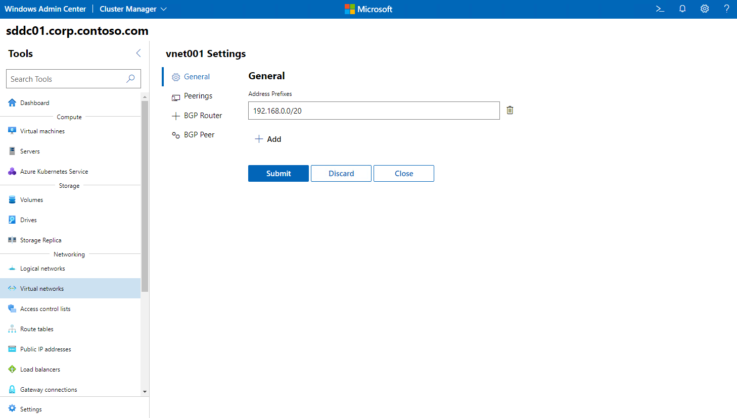
The following screenshot depicts some of the settings you can use to perform common Azure Stack HCI tenant virtual network configuration tasks, such as:
- Updating virtual network address prefixes
- Configuring virtual network peering
- Configuring Border Gateway Protocol (BGP) router and peers
Use the following procedure in Windows Admin Center to modify the settings of a subnet to a tenant logical network:
- In Windows Admin Center, connect to the Azure Stack HCI cluster.
- In the Tools pane, in the Networking section, select Virtual networks.
- On the Virtual networks page, select the Inventory tab, next. Select the virtual network that you want to modify, and then select Settings.
- On the settings pane of the virtual network, use the General section settings to perform any of the following tasks:
- Remove or add address prefixes.
- Configure peering with another virtual network.
- Add a BGP router to the virtual network. This requires that you provide the BGP router name and autonomous system number (ASN) number.
- Add one or more BGP peers for the BGP router. This requires that you provide the name, address, and ASN number for each BGP peer.
- In the settings pane of the virtual network pane, select Submit.
Configure virtual network peering
Each individual virtual network is isolated from other virtual networks, forming a default security boundary for VMs deployed into that virtual network. Sometimes, you might need to extend the scope of isolation by connecting virtual networks together. This might be the case if you've deployed one workload in one virtual network, but you want other workloads deployed in different virtual networks to access this workload through its private IP address. Virtual network peering provides this functionality by combining the virtual routers in the two virtual networks so they can communicate directly with each other without having to traverse a gateway. In addition to simplicity, peering offers performance benefits with high-throughput, low-latency communication between the virtual networks.
The benefits of using virtual network peering include:
- Traffic between VMs in the peered virtual networks is routed through private IP addresses. The communication between the virtual networks doesn’t require virtual gateways.
- A low-latency, high-bandwidth connection exists between resources in different virtual networks.
- There’s no negative impact on workloads in either virtual network when establishing peering.
Peering introduces the following additional requirements and constraints:
- Peered virtual networks must have non-overlapping IP address spaces.
- After you peer a virtual network with another virtual network, you cannot add or delete address ranges in the address space.
Peering has the following characteristics:
- A peering is unidirectional. For peering to provide connectivity between two virtual networks, it’s necessary to create two peerings: one in each direction.
- After you peer virtual networks, the resources in either virtual network can directly connect with resources in the peered virtual network.
- Network latency between VMs in peered virtual networks is the same as the latency within a single virtual network.
- Network throughput is based on the bandwidth allowed for the VM. There are no additional restrictions on bandwidth imposed by the peering.
- You can apply ACLs in either virtual network to block access to or from other virtual networks or subnets.
- Peering is non-transitive. For example, if you peer a virtual network A with a virtual network B and virtual network B with a virtual network C, this doesn’t automatically provide direct connectivity between virtual networks A and C.
Windows Admin Center provides an intuitive interface for creating and configuring virtual network peerings. The configuration settings include options to:
- Allow access from the local virtual network to the peered virtual network.
- Allow traffic forwarding (for example, forwarding traffic originating from another virtual network) to the peered virtual network.
- Allow the use of a remote gateway on the local or remote virtual network.
Delete Azure Stack HCI tenant virtual networks
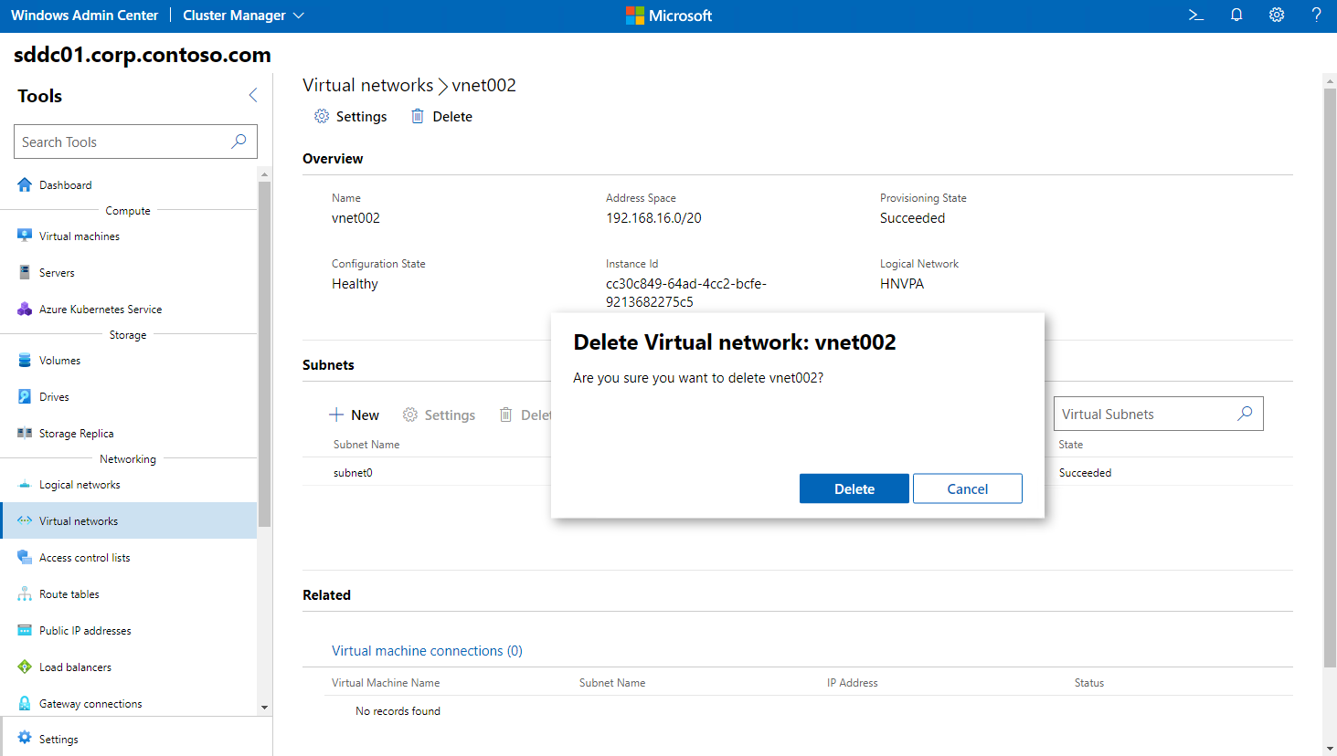
Windows Admin Center also simplifies the task of deleting Azure Stack HCI tenant virtual networks. To delete a tenant virtual network:
- In Windows Admin Center, connect to the Azure Stack HCI cluster.
- In the Tools pane, in the Networking section, select Virtual networks.
- On the Virtual networks page, select the Inventory tab, select the virtual network you intend to delete, and then select Delete.
- When prompted for confirmation, select Yes.


