MinnowBoard Max Pin Mappings
Note
To compare this pin mapping to newer versions of the Minnowboard, please visit documentation here.
Overview
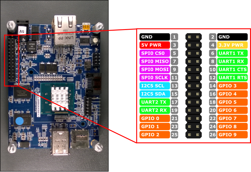
Hardware interfaces for the MinnowBoard Max are exposed through the 26-pin header JP1 on the board. Functionality includes:
- 10x - GPIO pins
- 2x - Serial UARTs
- 1x - SPI bus
- 1x - I2C bus
- 1x - 5V power pin
- 1x - 3.3V power pin
- 2x - Ground pins
The MinnowBoard Max uses 3.3V logic levels on all IO pins. In addition all the pins are buffered by TXS0104E level shifters, with the exception of power and ground pins. These level shifters appear as open collector outputs with a 10KΩ resistive pull-up, and the pull-up is present regardless of whether the IO is set to input or output.
The open-collector nature of the level shifters means is that the pins can output a '0' strongly, but only weakly output a '1'. This is important to keep in mind when attaching devices which draw current from the pins (such as an LED). See the Blinky Sample for the correct way to interface an LED to the MinnowBoard Max.
GPIO Pins
The following GPIO pins are accessible through APIs:
GPIO# Header Pin 0 21 1 23 2 25 3 14 4 16 5 18 6 20 7 22 8 24 9 26
Note: GPIO 4 and GPIO 5 are used by the MinnowBoard Max as bootstrap configuration pins for the BIOS. Make sure that attached devices do not drive these GPIO low during boot, as this could prevent the MBM from booting. After the MBM has booted past the BIOS, these GPIO can be used normally.
GPIO Sample
As an example, the following code opens GPIO 5 as an output and writes a digital '1' out on the pin:
using Windows.Devices.Gpio;

public void GPIO()
{
    GpioController Controller = GpioController.GetDefault(); /* Get the default GPIO controller on the system */

    GpioPin Pin = Controller.OpenPin(5);        /* Open GPIO 5                      */
    Pin.SetDriveMode(GpioPinDriveMode.Output);  /* Set the IO direction as output   */
    Pin.Write(GpioPinValue.High);               /* Output a digital '1'             */
}
Serial UART
There are two Serial UARTS available on the MBM: UART1 and UART2
UART1 has the standard UART1 TX and UART1 RX lines, along with flow control signals UART1 CTS and UART1 RTS.
- Pin 6 - UART1 TX
- Pin 8 - UART1 RX
- Pin 10 - UART1 CTS
- Pin 12 - UART1 RTS
UART1 is not working as of build 10240. Please use UART2 or a USB-Serial converter.
UART2 includes just the UART2 TX and UART2 RX lines.
- Pin 17 - UART2 TX
- Pin 19 - UART2 RX
UART2 does not support flow control, so accessing the following properties of SerialDevice can result in an exception being thrown:
- BreakSignalState
- IsDataTerminalReadyEnabled
- IsRequestToSendEnabled
- Handshake - only SerialHandshake.None is supported
The example below initializes UART2 and performs a write followed by a read:
using Windows.Storage.Streams;
using Windows.Devices.Enumeration;
using Windows.Devices.SerialCommunication;

public async void Serial()
{
    string aqs = SerialDevice.GetDeviceSelector("UART2");                   /* Find the selector string for the serial device   */
    var dis = await DeviceInformation.FindAllAsync(aqs);                    /* Find the serial device with our selector string  */
    SerialDevice SerialPort = await SerialDevice.FromIdAsync(dis[0].Id);    /* Create an serial device with our selected device */

    /* Configure serial settings */
    SerialPort.WriteTimeout = TimeSpan.FromMilliseconds(1000);
    SerialPort.ReadTimeout = TimeSpan.FromMilliseconds(1000);
    SerialPort.BaudRate = 9600;
    SerialPort.Parity = SerialParity.None;
    SerialPort.StopBits = SerialStopBitCount.One;
    SerialPort.DataBits = 8;

    /* Write a string out over serial */
    string txBuffer = "Hello Serial";
    DataWriter dataWriter = new DataWriter();
    dataWriter.WriteString(txBuffer);
    uint bytesWritten = await SerialPort.OutputStream.WriteAsync(dataWriter.DetachBuffer());

    /* Read data in from the serial port */
    const uint maxReadLength = 1024;
    DataReader dataReader = new DataReader(SerialPort.InputStream);
    uint bytesToRead = await dataReader.LoadAsync(maxReadLength);
    string rxBuffer = dataReader.ReadString(bytesToRead);
}
Note that you must add the following capability to the Package.appxmanifest file in your UWP project to run Serial UART code:
Visual Studio 2017 has a known bug in the Manifest Designer (the visual editor for appxmanifest files) that affects the serialcommunication capability. If your appxmanifest adds the serialcommunication capability, modifying your appxmanifest with the designer will corrupt your appxmanifest (the Device xml child will be lost). You can work around this problem by hand editing the appxmanifest by right-clicking your appxmanifest and selecting View Code from the context menu.
  <Capabilities>
    <DeviceCapability Name="serialcommunication">
      <Device Id="any">
        <Function Type="name:serialPort" />
      </Device>
    </DeviceCapability>
  </Capabilities>
I2C Bus
Let's look at the I2C bus available on this device.
I2C Overview
There is one I2C controller I2C5 exposed on the pin header with two lines SDA and SCL. 10KΩ internal pull-up resistors are already present on these lines.
- Pin 15 - I2C5 SDA
- Pin 13 - I2C5 SCL
I2C Sample
The example below initializes I2C5 and writes data to an I2C device with address 0x40:
using Windows.Devices.Enumeration;
using Windows.Devices.I2c;

public async void I2C()
{
    // 0x40 is the I2C device address
    var settings = new I2cConnectionSettings(0x40);

    // FastMode = 400KHz
    settings.BusSpeed = I2cBusSpeed.FastMode;

    // Create an I2cDevice with the specified I2C settings
    var controller = await I2cController.GetDefaultAsync();

    using (I2cDevice device = controller.GetDevice(settings))
    {
        byte[] writeBuf = { 0x01, 0x02, 0x03, 0x04 };
        device.Write(writeBuf);
    }

}
I2C Issues
The MinnowBoard Max has a known issue with the I2C bus, which causes communication problems with certain I2C devices. Normally, an I2C device will acknowledge its address during a bus request. However, under certain conditions this acknowledge fails to propagate back through the level shifters to the MBM, and as a result the CPU thinks the device did not respond and cancels the bus transaction. The issue seems to be related to the TXS0104E level shifters on the IO pins, which can trigger prematurely due to voltage spikes on the line. The current workaround is to insert a 100-ohm resistor in series with the I2C SCK line, which helps suppress spikes. Not all devices are affected, so this workaround is only required if you are having trouble getting a bus response. One device that is known to require this workaround is the HTU21D.
SPI Bus
Let's look at the SPI bus available on this device.
SPI Overview
There is one SPI controller SPI0 available on the MBM:
- Pin 9 - SPI0 MOSI
- Pin 7 - SPI0 MISO
- Pin 11 - SPI0 SCLK
- Pin 5 - SPI0 CS0
SPI Sample
An example on how to perform a SPI write on bus SPI0 is shown below:
using Windows.Devices.Enumeration;
using Windows.Devices.Spi;

public async void SPI()
{
    // Use chip select line CS0
    var settings = new SpiConnectionSettings(0);
    // Set clock to 10MHz
    settings.ClockFrequency = 10000000;

    // Create an SpiDevice with the specified Spi settings
    var controller = await SpiController.GetDefaultAsync();

    using (SpiDevice device = controller.GetDevice(settings))
    {
        byte[] writeBuf = { 0x01, 0x02, 0x03, 0x04 };
        device.Write(writeBuf);
    }
}