Xamarin.Forms Shapes: Geometries
The Geometry class, and the classes that derive from it, enable you to describe the geometry of a 2D shape. Geometry objects can be simple, such as rectangles and circles, or composite, created from two or more geometry objects. In addition, more complex geometries can be created that include arcs and curves.
The Geometry class is the parent class for several classes that define different categories of geometries:
EllipseGeometry, which represents the geometry of an ellipse or circle.GeometryGroup, which represents a container that can combine multiple geometry objects into a single object.LineGeometry, which represents the geometry of a line.PathGeometry, which represents the geometry of a complex shape that can be composed of arcs, curves, ellipses, lines, and rectangles.RectangleGeometry, which represents the geometry of a rectangle or square.
Note
There's also a RoundedRectangleGeometry class that derives from the GeometryGroup class. For more information, see RoundRectangleGeometry.
The Geometry and Shape classes seem similar, in that they both describe 2D shapes, but have an important difference. The Geometry class derives from the BindableObject class, while the Shape class derives from the View class. Therefore, Shape objects can render themselves and participate in the layout system, while Geometry objects cannot. While Shape objects are more readily usable than Geometry objects, Geometry objects are more versatile. While a Shape object is used to render 2D graphics, a Geometry object can be used to define the geometric region for 2D graphics, and define a region for clipping.
The following classes have properties that can be set to Geometry objects:
- The
Pathclass uses aGeometryto describe its contents. You can render aGeometryby setting thePath.Dataproperty to aGeometryobject, and setting thePathobject'sFillandStrokeproperties. - The
VisualElementclass has aClipproperty, of typeGeometry, that defines the outline of the contents of an element. When theClipproperty is set to aGeometryobject, only the area that is within the region of theGeometrywill be visible. For more information, see Clip with a Geometry.
The classes that derive from the Geometry class can be grouped into three categories: simple geometries, path geometries, and composite geometries.
Simple geometries
The simple geometry classes are EllipseGeometry, LineGeometry, and RectangleGeometry. They are used to create basic geometric shapes, such as circles, lines, and rectangles. These same shapes, as well as more complex shapes, can be created using a PathGeometry or by combining geometry objects together, but these classes provide a simpler approach for producing these basic geometric shapes.
EllipseGeometry
An ellipse geometry represents the geometry or an ellipse or circle, and is defined by a center point, an x-radius, and a y-radius.
The EllipseGeometry class defines the following properties:
Center, of typePoint, which represents the center point of the geometry.RadiusX, of typedouble, which represents the x-radius value of the geometry. The default value of this property is 0.0.RadiusY, of typedouble, which represents the y-radius value of the geometry. The default value of this property is 0.0.
These properties are backed by BindableProperty objects, which means that they can be targets of data bindings, and styled.
The following example shows how to create and render an EllipseGeometry in a Path object:
<Path Fill="Blue"
      Stroke="Red">
  <Path.Data>
    <EllipseGeometry Center="50,50"
                     RadiusX="50"
                     RadiusY="50" />
  </Path.Data>
</Path>
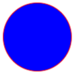
In this example, the center of the EllipseGeometry is set to (50,50) and the x-radius and y-radius are both set to 50. This creates a red circle with a diameter of 100 device-independent units, whose interior is painted blue:
LineGeometry
A line geometry represents the geometry of a line, and is defined by specifying the start point of the line and the end point.
The LineGeometry class defines the following properties:
StartPoint, of typePoint, which represents the start point of the line.EndPoint, of typePoint, which represents the end point of the line.
These properties are backed by BindableProperty objects, which means that they can be targets of data bindings, and styled.
The following example shows how to create and render a LineGeometry in a Path object:
<Path Stroke="Black">
  <Path.Data>
    <LineGeometry StartPoint="10,20"
                  EndPoint="100,130" />
  </Path.Data>
</Path>
In this example, a LineGeometry is drawn from (10,20) to (100,130):

Note
Setting the Fill property of a Path that renders a LineGeometry will have no effect, because a line has no interior.
RectangleGeometry
A rectangle geometry represents the geometry of a rectangle or square, and is defined with a Rect structure that specifies its relative position and its height and width.
The RectangleGeometry class defines the Rect property, of type Rect, which represents the dimensions of the rectangle. This property is backed by a BindableProperty object, which means that it can be the target of data bindings, and styled.
The following example shows how to create and render a RectangleGeometry in a Path object:
<Path Fill="Blue"
      Stroke="Red">
  <Path.Data>
    <RectangleGeometry Rect="10,10,150,100" />
  </Path.Data>
</Path>
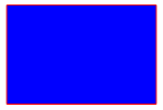
The position and dimensions of the rectangle are defined by a Rect structure. In this example, the position is (10,10), the width is 150, and the height is 100 device-independent units:
Path geometries
A path geometry describes a complex shape that can be composed of arcs, curves, ellipses, lines, and rectangles.
The PathGeometry class defines the following properties:
Figures, of typePathFigureCollection, which represents the collection ofPathFigureobjects that describe the path's contents.FillRule, of typeFillRule, which determines how the intersecting areas contained in the geometry are combined. The default value of this property isFillRule.EvenOdd.
These properties are backed by BindableProperty objects, which means that they can be targets of data bindings, and styled.
For more information about the FillRule enumeration, see Xamarin.Forms Shapes: Fill rules.
Note
The Figures property is the ContentProperty of the PathGeometry class, and so does not need to be explicitly set from XAML.
A PathGeometry is made up of a collection of PathFigure objects, with each PathFigure describing a shape in the geometry. Each PathFigure is itself comprised of one or more PathSegment objects, each of which describes a segment of the shape. There are many types of segments:
ArcSegment, which creates an elliptical arc between two points.BezierSegment, which creates a cubic Bezier curve between two points.LineSegment, which creates a line between two points.PolyBezierSegment, which creates a series of cubic Bezier curves.PolyLineSegment, which creates a series of lines.PolyQuadraticBezierSegment, which creates a series of quadratic Bezier curves.QuadraticBezierSegment, which creates a quadratic Bezier curve.
All the above classes derive from the abstract PathSegment class.
The segments within a PathFigure are combined into a single geometric shape with the end point of each segment being the start point of the next segment. The StartPoint property of a PathFigure specifies the point from which the first segment is drawn. Each subsequent segment starts at the end point of the previous segment. For example, a vertical line from 10,50 to 10,150 can be defined by setting the StartPoint property to 10,50 and creating a LineSegment with a Point property setting of 10,150:
<Path Stroke="Black">
    <Path.Data>
        <PathGeometry>
            <PathGeometry.Figures>
                <PathFigureCollection>
                    <PathFigure StartPoint="10,50">
                        <PathFigure.Segments>
                            <PathSegmentCollection>
                                <LineSegment Point="10,150" />
                            </PathSegmentCollection>
                        </PathFigure.Segments>
                    </PathFigure>
                </PathFigureCollection>
            </PathGeometry.Figures>
        </PathGeometry>
    </Path.Data>
</Path>
More complex geometries can be created by using a combination of PathSegment objects, and by using multiple PathFigure objects within a PathGeometry.
Create an ArcSegment
An ArcSegment creates an elliptical arc between two points. An elliptical arc is defined by its start and end points, x- and y-radius, x-axis rotation factor, a value indicating whether the arc should be greater than 180 degrees, and a value describing the direction in which the arc is drawn.
The ArcSegment class defines the following properties:
Point, of typePoint, which represents the endpoint of the elliptical arc. The default value of this property is (0,0).Size, of typeSize, which represents the x- and y-radius of the arc. The default value of this property is (0,0).RotationAngle, of typedouble, which represents the amount in degrees by which the ellipse is rotated around the x-axis. The default value of this property is 0.SweepDirection, of typeSweepDirection, which specifies the direction in which the arc is drawn. The default value of this property isSweepDirection.CounterClockwise.IsLargeArc, of typebool, which indicates whether the arc should be greater than 180 degrees. The default value of this property isfalse.
These properties are backed by BindableProperty objects, which means that they can be targets of data bindings, and styled.
Note
The ArcSegment class does not contain a property for the starting point of the arc. It only defines the end point of the arc it represents. The start point of the arc is the current point of the PathFigure to which the ArcSegment is added.
The SweepDirection enumeration defines the following members:
CounterClockwise, which specifies that arcs are drawn in a counter clockwise direction.Clockwise, which specifies that arcs are drawn in a clockwise direction.
The following example shows how to create and render an ArcSegment in a Path object:
<Path Stroke="Black">
    <Path.Data>
        <PathGeometry>
            <PathGeometry.Figures>
                <PathFigureCollection>
                    <PathFigure StartPoint="10,10">
                        <PathFigure.Segments>
                            <PathSegmentCollection>
                                <ArcSegment Size="100,50"
                                            RotationAngle="45"
                                            IsLargeArc="True"
                                            SweepDirection="CounterClockwise"
                                            Point="200,100" />
                            </PathSegmentCollection>
                        </PathFigure.Segments>
                    </PathFigure>
                </PathFigureCollection>
            </PathGeometry.Figures>
        </PathGeometry>
    </Path.Data>
</Path>
In this example, an elliptical arc is drawn from (10,10) to (200,100).
Create a BezierSegment
A BezierSegment creates a cubic Bezier curve between two points. A cubic Bezier curve is defined by four points: a start point, an end point, and two control points.
The BezierSegment class defines the following properties:
Point1, of typePoint, which represents the first control point of the curve. The default value of this property is (0,0).Point2, of typePoint, which represents the second control point of the curve. The default value of this property is (0,0).Point3, of typePoint, which represents the end point of the curve. The default value of this property is (0,0).
These properties are backed by BindableProperty objects, which means that they can be targets of data bindings, and styled.
Note
The BezierSegment class does not contain a property for the starting point of the curve. The start point of the curve is the current point of the PathFigure to which the BezierSegment is added.
The two control points of a cubic Bezier curve behave like magnets, attracting portions of what would otherwise be a straight line toward themselves and producing a curve. The first control point affects the start portion of the curve. The second control point affects the end portion of the curve. The curve doesn't necessarily pass through either of the control points. Instead, each control point moves its portion of the line toward itself, but not through itself.
The following example shows how to create and render a BezierSegment in a Path object:
<Path Stroke="Black">
    <Path.Data>
        <PathGeometry>
            <PathGeometry.Figures>
                <PathFigureCollection>
                    <PathFigure StartPoint="10,10">
                        <PathFigure.Segments>
                            <PathSegmentCollection>
                                <BezierSegment Point1="100,0"
                                               Point2="200,200"
                                               Point3="300,10" />
                            </PathSegmentCollection>
                        </PathFigure.Segments>
                    </PathFigure>
                </PathFigureCollection>
            </PathGeometry.Figures>
        </PathGeometry>
    </Path.Data>
</Path>
In this example, a cubic Bezier curve is drawn from (10,10) to (300,10). The curve has two control points at (100,0) and (200,200):

Create a LineSegment
A LineSegment creates a line between two points.
The LineSegment class defines the Point property, of type Point, which represents the end point of the line segment. The default value of this property is (0,0), and it's backed by a BindableProperty object, which means that it can be the target of data bindings, and styled.
Note
The LineSegment class does not contain a property for the starting point of the line. It only defines the end point. The start point of the line is the current point of the PathFigure to which the LineSegment is added.
The following example shows how to create and render LineSegment objects in a Path object:
<Path Stroke="Black"
      Aspect="Uniform"
      HorizontalOptions="Start">
    <Path.Data>
        <PathGeometry>
            <PathGeometry.Figures>
                <PathFigureCollection>
                    <PathFigure IsClosed="True"
                                StartPoint="10,100">
                        <PathFigure.Segments>
                            <PathSegmentCollection>
                                <LineSegment Point="100,100" />
                                <LineSegment Point="100,50" />
                            </PathSegmentCollection>
                        </PathFigure.Segments>
                    </PathFigure>
                </PathFigureCollection>
            </PathGeometry.Figures>
        </PathGeometry>
    </Path.Data>
</Path>
In this example, a line segment is drawn from (10,100) to (100,100), and from (100,100) to (100,50). In addition, the PathFigure is closed because its IsClosed property is set to true. This results in a triangle being drawn:

Create a PolyBezierSegment
A PolyBezierSegment creates one or more cubic Bezier curves.
The PolyBezierSegment class defines the Points property, of type PointCollection, which represents the points that define the PolyBezierSegment. A PointCollection is an ObservableCollection of Point objects. This property is backed by a BindableProperty object, which means that it can be the target of data bindings, and styled.
Note
The PolyBezierSegment class does not contain a property for the starting point of the curve. The start point of the curve is the current point of the PathFigure to which the PolyBezierSegment is added.
The following example shows how to create and render a PolyBezierSegment in a Path object:
<Path Stroke="Black">
    <Path.Data>
        <PathGeometry>
            <PathGeometry.Figures>
                <PathFigureCollection>
                    <PathFigure StartPoint="10,10">
                        <PathFigure.Segments>
                            <PathSegmentCollection>
                                <PolyBezierSegment Points="0,0 100,0 150,100 150,0 200,0 300,10" />
                            </PathSegmentCollection>
                        </PathFigure.Segments>
                    </PathFigure>
                </PathFigureCollection>
            </PathGeometry.Figures>
        </PathGeometry>
    </Path.Data>
</Path>
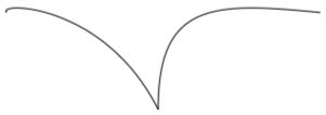
In this example, the PolyBezierSegment specifies two cubic Bezier curves. The first curve is from (10,10) to (150,100) with a control point of (0,0), and another control point of (100,0). The second curve is from (150,100) to (300,10) with a control point of (150,0) and another control point of (200,0):
Create a PolyLineSegment
A PolyLineSegment creates one or more line segments.
The PolyLineSegment class defines the Points property, of type PointCollection, which represents the points that define the PolyLineSegment. A PointCollection is an ObservableCollection of Point objects. This property is backed by a BindableProperty object, which means that it can be the target of data bindings, and styled.
Note
The PolyLineSegment class does not contain a property for the starting point of the line. The start point of the line is the current point of the PathFigure to which the PolyLineSegment is added.
The following example shows how to create and render a PolyLineSegment in a Path object:
<Path Stroke="Black">
    <Path.Data>
        <PathGeometry>
            <PathGeometry.Figures>
                <PathFigure StartPoint="10,10">
                    <PathFigure.Segments>
                        <PolyLineSegment Points="50,10 50,50" />
                    </PathFigure.Segments>
                </PathFigure>
            </PathGeometry.Figures>
        </PathGeometry>
    </Path.Data>
</Path>
In this example, the PolyLineSegment specifies two lines. The first line is from (10,10) to (50,10), and the second line is from (50,10) to (50,50):

Create a PolyQuadraticBezierSegment
A PolyQuadraticBezierSegment creates one or more quadratic Bezier curves.
The PolyQuadraticBezierSegment class defines the Points property, of type PointCollection, which represents the points that define the PolyQuadraticBezierSegment. A PointCollection is an ObservableCollection of Point objects. This property is backed by a BindableProperty object, which means that it can be the target of data bindings, and styled.
Note
The PolyQuadraticBezierSegment class does not contain a property for the starting point of the curve. The start point of the curve is the current point of the PathFigure to which the PolyQuadraticBezierSegment is added.
The following example shows to create and render a PolyQuadraticBezierSegment in a Path object:
<Path Stroke="Black">
    <Path.Data>
        <PathGeometry>
            <PathGeometry.Figures>
                <PathFigureCollection>
                    <PathFigure StartPoint="10,10">
                        <PathFigure.Segments>
                            <PathSegmentCollection>
                                <PolyQuadraticBezierSegment Points="100,100 150,50 0,100 15,200" />
                            </PathSegmentCollection>
                        </PathFigure.Segments>
                    </PathFigure>
                </PathFigureCollection>
            </PathGeometry.Figures>
        </PathGeometry>
    </Path.Data>
</Path>
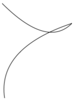
In this example, the PolyQuadraticBezierSegment specifies two Bezier curves. The first curve is from (10,10) to (150,50) with a control point at (100,100). The second curve is from (100,100) to (15,200) with a control point at (0,100):
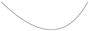
Create a QuadraticBezierSegment
A QuadraticBezierSegment creates a quadratic Bezier curve between two points.
The QuadraticBezierSegment class defines the following properties:
Point1, of typePoint, which represents the control point of the curve. The default value of this property is (0,0).Point2, of typePoint, which represents the end point of the curve. The default value of this property is (0,0).
These properties are backed by BindableProperty objects, which means that they can be targets of data bindings, and styled.
Note
The QuadraticBezierSegment class does not contain a property for the starting point of the curve. The start point of the curve is the current point of the PathFigure to which the QuadraticBezierSegment is added.
The following example shows how to create and render a QuadraticBezierSegment in a Path object:
<Path Stroke="Black">
    <Path.Data>
        <PathGeometry>
            <PathGeometry.Figures>
                <PathFigureCollection>
                    <PathFigure StartPoint="10,10">
                        <PathFigure.Segments>
                            <PathSegmentCollection>
                                <QuadraticBezierSegment Point1="200,200"
                                                        Point2="300,10" />
                            </PathSegmentCollection>
                        </PathFigure.Segments>
                    </PathFigure>
                </PathFigureCollection>
            </PathGeometry.Figures>
        </PathGeometry>
    </Path.Data>
</Path>
In this example, a quadratic Bezier curve is drawn from (10,10) to (300,10). The curve has a control point at (200,200):
Create complex geometries
More complex geometries can be created by using a combination of PathSegment objects. The following example creates a shape using a BezierSegment, a LineSegment, and an ArcSegment:
<Path Stroke="Black">
    <Path.Data>
        <PathGeometry>
            <PathGeometry.Figures>
                <PathFigure StartPoint="10,50">
                    <PathFigure.Segments>
                        <BezierSegment Point1="100,0"
                                       Point2="200,200"
                                       Point3="300,100"/>
                        <LineSegment Point="400,100" />
                        <ArcSegment Size="50,50"
                                    RotationAngle="45"
                                    IsLargeArc="True"
                                    SweepDirection="Clockwise"
                                    Point="200,100"/>
                    </PathFigure.Segments>
                </PathFigure>
            </PathGeometry.Figures>
        </PathGeometry>
    </Path.Data>
</Path>
In this example, a BezierSegment is first defined using four points. The example then adds a LineSegment, which is drawn between the end point of the BezierSegment to the point specified by the LineSegment. Finally, an ArcSegment is drawn from the end point of the LineSegment to the point specified by the ArcSegment.
Even more complex geometries can be created by using multiple PathFigure objects within a PathGeometry. The following example creates a PathGeometry from seven PathFigure objects, some of which contain multiple PathSegment objects:
<Path Stroke="Red"
      StrokeThickness="12"
      StrokeLineJoin="Round">
    <Path.Data>
        <PathGeometry>
            <!-- H -->
            <PathFigure StartPoint="0,0">
                <LineSegment Point="0,100" />
            </PathFigure>
            <PathFigure StartPoint="0,50">
                <LineSegment Point="50,50" />
            </PathFigure>
            <PathFigure StartPoint="50,0">
                <LineSegment Point="50,100" />
            </PathFigure>

            <!-- E -->
            <PathFigure StartPoint="125, 0">
                <BezierSegment Point1="60, -10"
                               Point2="60, 60"
                               Point3="125, 50" />
                <BezierSegment Point1="60, 40"
                               Point2="60, 110"
                               Point3="125, 100" />
            </PathFigure>

            <!-- L -->
            <PathFigure StartPoint="150, 0">
                <LineSegment Point="150, 100" />
                <LineSegment Point="200, 100" />
            </PathFigure>

            <!-- L -->
            <PathFigure StartPoint="225, 0">
                <LineSegment Point="225, 100" />
                <LineSegment Point="275, 100" />
            </PathFigure>

            <!-- O -->
            <PathFigure StartPoint="300, 50">
                <ArcSegment Size="25, 50"
                            Point="300, 49.9"
                            IsLargeArc="True" />
            </PathFigure>
        </PathGeometry>
    </Path.Data>
</Path>
In this example, the word "Hello" is drawn using a combination of LineSegment and BezierSegment objects, along with a single ArcSegment object:

Composite geometries
Composite geometry objects can be created using a GeometryGroup. The GeometryGroup class creates a composite geometry from one or more Geometry objects. Any number of Geometry objects can be added to a GeometryGroup.
The GeometryGroup class defines the following properties:
Children, of typeGeometryCollection, which specifies the objects that define theGeomtryGroup. AGeometryCollectionis anObservableCollectionofGeometryobjects.FillRule, of typeFillRule, which specifies how the intersecting areas in theGeometryGroupare combined. The default value of this property isFillRule.EvenOdd.
These properties are backed by BindableProperty objects, which means that they can be targets of data bindings, and styled.
Note
The Children property is the ContentProperty of the GeometryGroup class, and so does not need to be explicitly set from XAML.
For more information about the FillRule enumeration, see Xamarin.Forms Shapes: Fill rules.
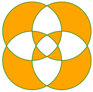
To draw a composite geometry, set the required Geometry objects as the children of a GeometryGroup, and display them with a Path object. The following XAML shows an example of this:
<Path Stroke="Green"
      StrokeThickness="2"
      Fill="Orange">
    <Path.Data>
        <GeometryGroup>
            <EllipseGeometry RadiusX="100"
                             RadiusY="100"
                             Center="150,150" />
            <EllipseGeometry RadiusX="100"
                             RadiusY="100"
                             Center="250,150" />
            <EllipseGeometry RadiusX="100"
                             RadiusY="100"
                             Center="150,250" />
            <EllipseGeometry RadiusX="100"
                             RadiusY="100"
                             Center="250,250" />
        </GeometryGroup>
    </Path.Data>
</Path>
In this example, four EllipseGeometry objects with identical x-radius and y-radius coordinates, but with different center coordinates, are combined. This creates four overlapping circles, whose interiors are filled orange due to the default EvenOdd fill rule:
RoundRectangleGeometry
A round rectangle geometry represents the geometry of a rectangle, or square, with rounded corners, and is defined by a corner radius and a Rect structure that specifies its relative position and its height and width.
The RoundRectangleGeometry class, which derives from the GeometryGroup class, defines the following properties:
CornerRadius, of typeCornerRadius, which is the corner radius of the geometry.Rect, of typeRect, which represents the dimensions of the rectangle.
These properties are backed by BindableProperty objects, which means that they can be targets of data bindings, and styled.
Note
The fill rule used by the RoundRectangleGeometry is FillRule.Nonzero. For more information about fill rules, see Xamarin.Forms Shapes: Fill rules.
The following example shows how to create and render a RoundRectangleGeometry in a Path object:
<Path Fill="Blue"
      Stroke="Red">
    <Path.Data>
        <RoundRectangleGeometry CornerRadius="5"
                                Rect="10,10,150,100" />
    </Path.Data>
</Path>
The position and dimensions of the rectangle are defined by a Rect structure. In this example, the position is (10,10), the width is 150, and the height is 100 device-independent units. In addition, the rectangle corners are rounded with a radius of 5 device-independent units.
Clip with a Geometry
The VisualElement class has a Clip property, of type Geometry, that defines the outline of the contents of an element. When the Clip property is set to a Geometry object, only the area that is within the region of the Geometry will be visible.
The following example shows how to use a Geometry object as the clip region for an Image:
<Image Source="monkeyface.png">
    <Image.Clip>
        <EllipseGeometry RadiusX="100"
                         RadiusY="100"
                         Center="180,180" />
    </Image.Clip>
</Image>
In this example, an EllipseGeometry with RadiusX and RadiusY values of 100, and a Center value of (180,180) is set to the Clip property of an Image. Only the part of the image that is within the area of the ellipse will be displayed:

Note
Simple geometries, path geometries, and composite geometries can all be used to clip VisualElement objects.
Other features
The GeometryHelper class provides the following helper methods:
FlattenGeometry, which flattens aGeometryinto aPathGeometry.FlattenCubicBezier, which flattens a cubic Bezier curve into aList<Point>collection.FlattenQuadraticBezier, which flattens a quadratic Bezier curve into aList<Point>collection.FlattenArc, which flattens an elliptical arc into aList<Point>collection.
 Download the sample