Note
Access to this page requires authorization. You can try signing in or changing directories.
Access to this page requires authorization. You can try changing directories.
This article is one in a series of articles describing the deployment path for OT monitoring with Microsoft Defender for IoT.
Use the content below to learn about your own operational technology (OT)/IoT network architecture, and where each of your system elements falls into layers of OT network segmentation.

OT/IoT networking layers
Your organization’s network consists of many device types, which can be divided into the following main groups:
- Endpoint devices. Can include multiple sub-groups, such as servers, computers, IoT (internet of things) devices, and so on.
- Network devices. Serve the infrastructure with networking services, and can include network switches, firewalls, routers, and access points.
Most networks environments are designed with hierarchical model of three layers. For example:
| Layer | Description |
|---|---|
| Access | The access layer is where most endpoints will be located. These endpoints are typically served by a default gateway and routing from the upper layers, and often, routing from the distribution layer. * A default gateway is a network service or entity within the local subnet that is responsible for routing traffic outside of the LAN, or IP segment. |
| Distribution | The distribution layer is responsible for aggregating multiple access layers and delivering communication to the core layer with services like VLAN routing, quality of service, network policies, and so on. |
| Core | The core layer contains the organization's main server farm, and provides high-speed, low-latency services via the distribution layer. |
The Purdue model of networking architecture
The Purdue Reference Model for Industrial Control System (ICS)/OT network segmentation defines a further six layers, with specific components and relevant security controls for each layer.
Each device type in your OT network falls in a specific level of the Purdue model, for example, as shown in the following image:

The following table describes each level of the Purdue model when applied to devices you may have in your network:
| Name | Description |
|---|---|
| Level 0: Cell and area | Level 0 consists of a wide variety of sensors, actuators, and devices involved in the basic manufacturing process. These devices perform the basic functions of the industrial automation and control system, such as: - Driving a motor - Measuring variables - Setting an output - Performing key functions, such as painting, welding, and bending |
| Level 1: Process control | Level 1 consists of embedded controllers that control and manipulate the manufacturing process whose key function is to communicate with the Level 0 devices. In discrete manufacturing, those devices are programmable logic controllers (PLCs) or remote telemetry units (RTUs). In process manufacturing, the basic controller is called a distributed control system (DCS). |
| Level 2: Supervisory | Level 2 represents the systems and functions associated with the runtime supervision and operation of an area of a production facility. These usually include the following: - Operator interfaces or human-machine interfaces (HMIs) - Alarms or alerting systems - Process historian and batch management systems - Control room workstations These systems communicate with the PLCs and RTUs in Level 1. In some cases, they communicate or share data with the site or enterprise (Level 4 and Level 5) systems and applications. These systems are primarily based on standard computing equipment and operating systems (Unix or Microsoft Windows). |
| Levels 3 and 3.5: Site-level and industrial perimeter network | The site level represents the highest level of industrial automation and control systems. The systems and applications that exist at this level manage site-wide industrial automation and control functions. Levels 0 through 3 are considered critical to site operations. The systems and functions that exist at this level might include the following: - Production reporting (for example, cycle times, quality index, predictive maintenance) - Plant historian - Detailed production scheduling - Site-level operations management - Device and material management - Patch launch server - File server - Industrial domain, Active Directory, terminal server These systems communicate with the production zone and share data with the enterprise (Level 4 and Level 5) systems and applications. |
| Levels 4 and 5: Business and enterprise networks | Level 4 and Level 5 represent the site or enterprise network where the centralized IT systems and functions exist. The IT organization directly manages the services, systems, and applications at these levels. |
Placing OT sensors in your network
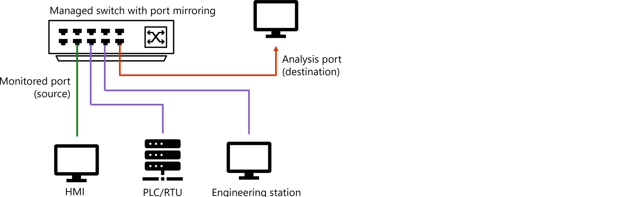
When Defender for IoT network sensors are connected to your network infrastructure, they receive mirrored traffic, such as from switch mirror (SPAN) ports or network TAPs. The sensor's management port connects to the business, corporate, or sensor management network, such as for network management from the Azure portal.
For example:
The following image adds Defender for IoT resources to the same network as described earlier, including a SPAN port, network sensor, and Defender for IoT in the Azure portal.

For more information, see Sample OT network connectivity models.
Identifying interesting traffic points
Typically, interesting points from a security perspective are the interfaces that connect between the default gateway entity to the core or distribution switch.
Identifying these interfaces as interesting points ensures that traffic traveling from inside the IP segment to outside the IP segment is monitored. Make sure to also consider missing traffic, which is traffic that was originally destined to leave the segment, but ends up remaining inside the segment. For more information, see Traffic flows in your network.
When planning a Defender for IoT deployment, we recommend considering the following elements in your network:
| Consideration | Description |
|---|---|
| Unique traffic types inside a segment | Especially consider the following types of traffic inside a network segment: Broadcast / Multicast traffic: Traffic sent to any entity within the subnet. With Internet Group Management Protocol (IGMP), snooping is configured within your network, but there's no guarantee that multicast traffic is forwarded to any specific entity. Broadcast and multicast traffic is typically sent to all entities in the local IP subnet, including the default gateway entity, and is therefore also covered and monitored. Unicast traffic: Traffic forwarded directly to the destination, without crossing the entire subnet endpoints, including the default gateway. Monitor unicast traffic with Defender for IoT by placing sensors directly on the access switches. |
| Monitor both streams of traffic | When streaming traffic to Defender for IoT, some vendors and products allow a direction stream, which can cause a gap in your data. It’s very useful to monitor both directions of traffic to get network conversation information about your subnets and better accuracy in general. |
| Find a subnet's default gateway | For each interesting subnet, the interesting point will be any connection to the entity that acts as the default gateway for the network subnet. However, in some cases, there's traffic within the subnet that isn’t monitored by the regular interesting point. Monitoring this type of traffic, which isn’t otherwise monitored by the typical deployment, is useful especially on sensitive subnets. |
| Atypical traffic | Monitoring traffic that isn’t otherwise monitored by the typical deployment may require extra streaming points and network solutions, such as RSPAN, network tappers, and so on. For more information, see Traffic mirroring methods for OT monitoring. |
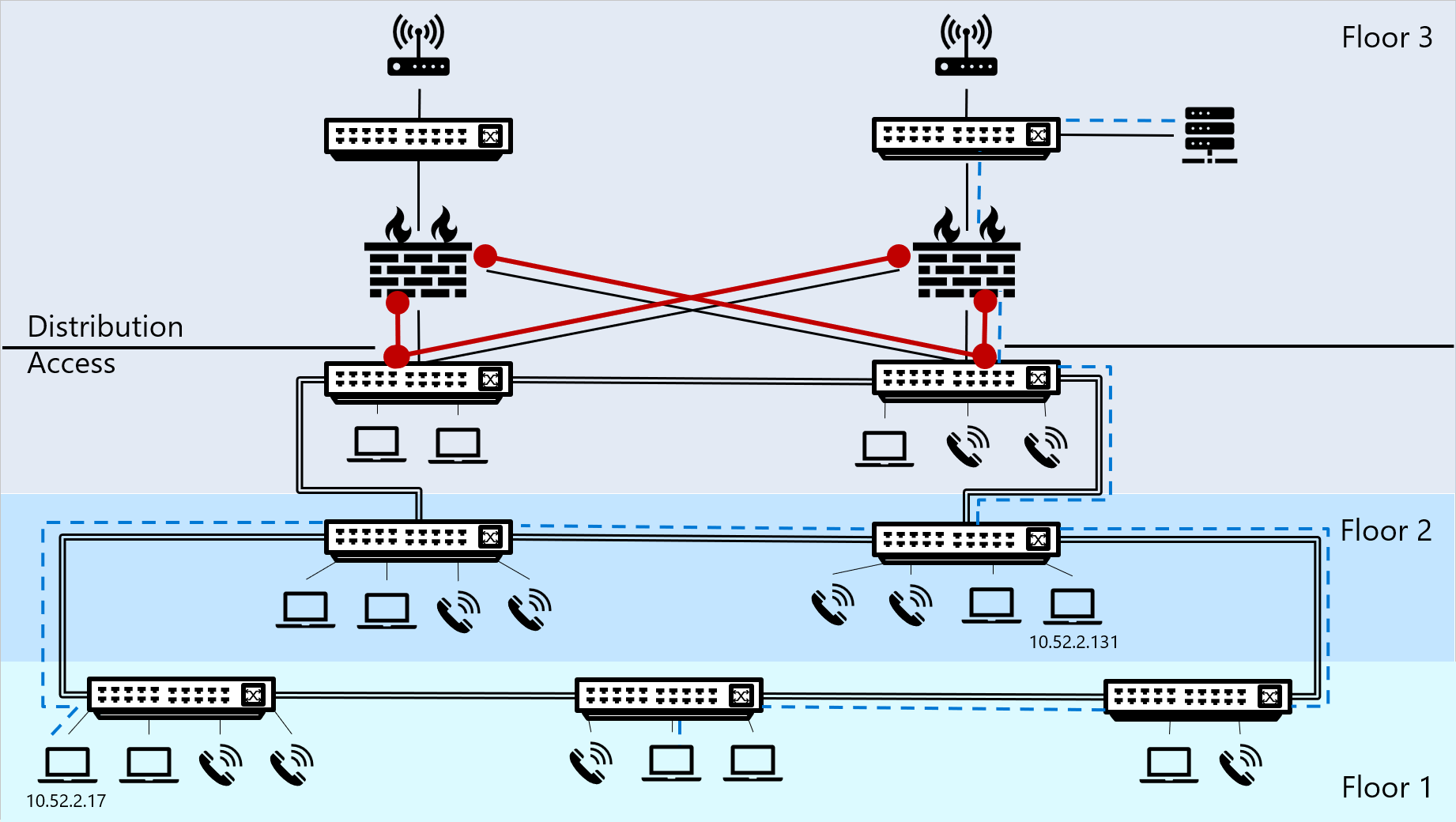
Sample traffic diagram
The following diagram shows a sample network in a building of three floors, where the first and second floors house both endpoints and switches, and the third-floor houses endpoints and switches, but also firewalls, core switches, a server, and routers.
Traffic traveling outside of the IP segment is shown by a blue dotted line.
Interesting traffic is marked in red, and indicates the places where we'd recommend putting network sensors to stream that interesting traffic to Defender for IoT.
Traffic flows in your network
Devices that trigger network traffic match the configured subnet mask and IP address with a destination IP address to understand what the traffic’s destination should be. The traffic's destination will be either the default gateway or elsewhere inside the IP segment. This matching process can also trigger an ARP process to find the MAC address for the destination IP address.
Based on the results of the matching process, devices track their network traffic as either traffic within or outside of the IP segment.
| Traffic | Description | Example |
|---|---|---|
| Traffic outside of the IP segment | When the traffic destination isn't found within the subnet mask’s range, the endpoint device sends the traffic to the specific default gateway that’s responsible for routing traffic flow to other relevant segments. Any traffic traveling outside of an IP segment flows through a default gateway to cross the network segment, as a first hop in the path to its destination. Note: Placing a Defender for IoT OT network sensor at this point ensures that all traffic traveling outside of the segment is streamed to Defender for IoT, analyzed, and can be investigated. |
- A PC is configured with an IP address of 10.52.2.201 and a subnet mask of 255.255.255.0. - The PC triggers a network flow to a web server with a destination IP address of 10.17.0.88. - The PC’s operating system calculates the destination IP address with the range of IP addresses in the segment to determine if the traffic should be sent locally, inside the segment, or direct to the default gateway entity that can find the correct route to the destination. - Based on the calculation’s results, the operating system finds that for the IP and subnet peer ( 10.52.2.17 and 255.255.255.0), the segment range is 10.52.2.0 – 10.52.2.255. The results mean that the web server is not within the same IP Segment as the PC, and the traffic should be sent to the default gateway. |
| Traffic within the IP segment | If the device finds the destination IP address within the subnet mask range, the traffic doesn’t cross the IP segment, and travels inside the segment to find the destination MAC address. This traffic requires an ARP resolution, which triggers a broadcast packet to find the destination IP address’s MAC address. |
- A PC is configured with an IP address of 10.52.2.17 and a subnet mask of 255.255.255.0. - This PC triggers a network flow to another PC, with a destination address of 10.52.2.131. - The PC’s operating system calculates the destination IP address with the range of IP addresses in the segment to determine if the traffic should be sent locally, inside the segment, or direct to the default gateway entity that can find the correct route to the destination. - Based on the calculation’s results, the operating system finds that for the IP and subnet peer ( 10.52.2.17 and 255.255.255.0), the segment range is 10.52.2.0 – 10.52.2.255. The results mean that the PC’s destination IP address is within the same segment as the PC itself, and the traffic should be sent directly on the segment. |
Implementing Defender for IoT deployment with a unidirectional gateway
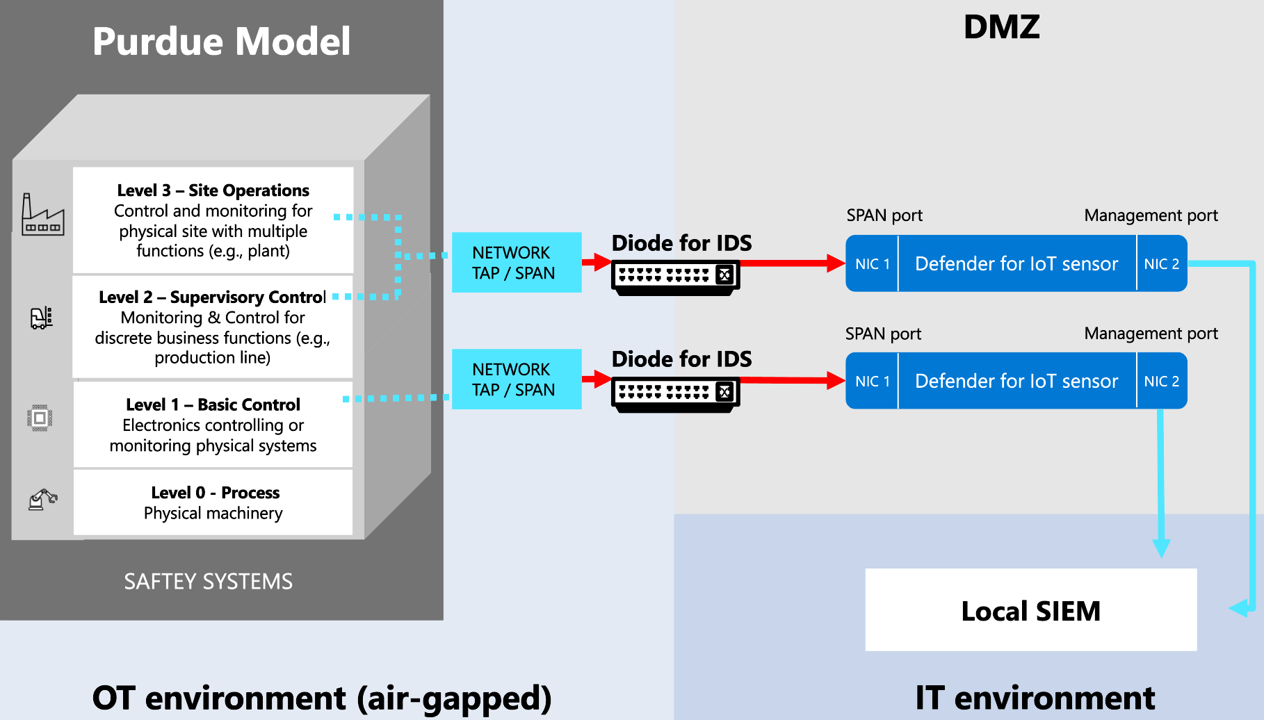
If you're working with a unidirectional gateway, such as Waterfall, Owl Cyber Defense, or Hirschmann, where data passes through a data diode in one direction only, use one of the following methods to understand where to place your OT sensors:
Place your OT sensors outside the network perimeter (Recommended). In this scenario, your sensor receives SPAN traffic through the diode, unidirectionally from the network to the sensor's monitoring port. We recommend using this method in large deployments. For example:
Place your OT sensors inside the network perimeter. In this scenario, the sensor sends UDP syslog alerts to targets outside the perimeter through the data diode. For example:
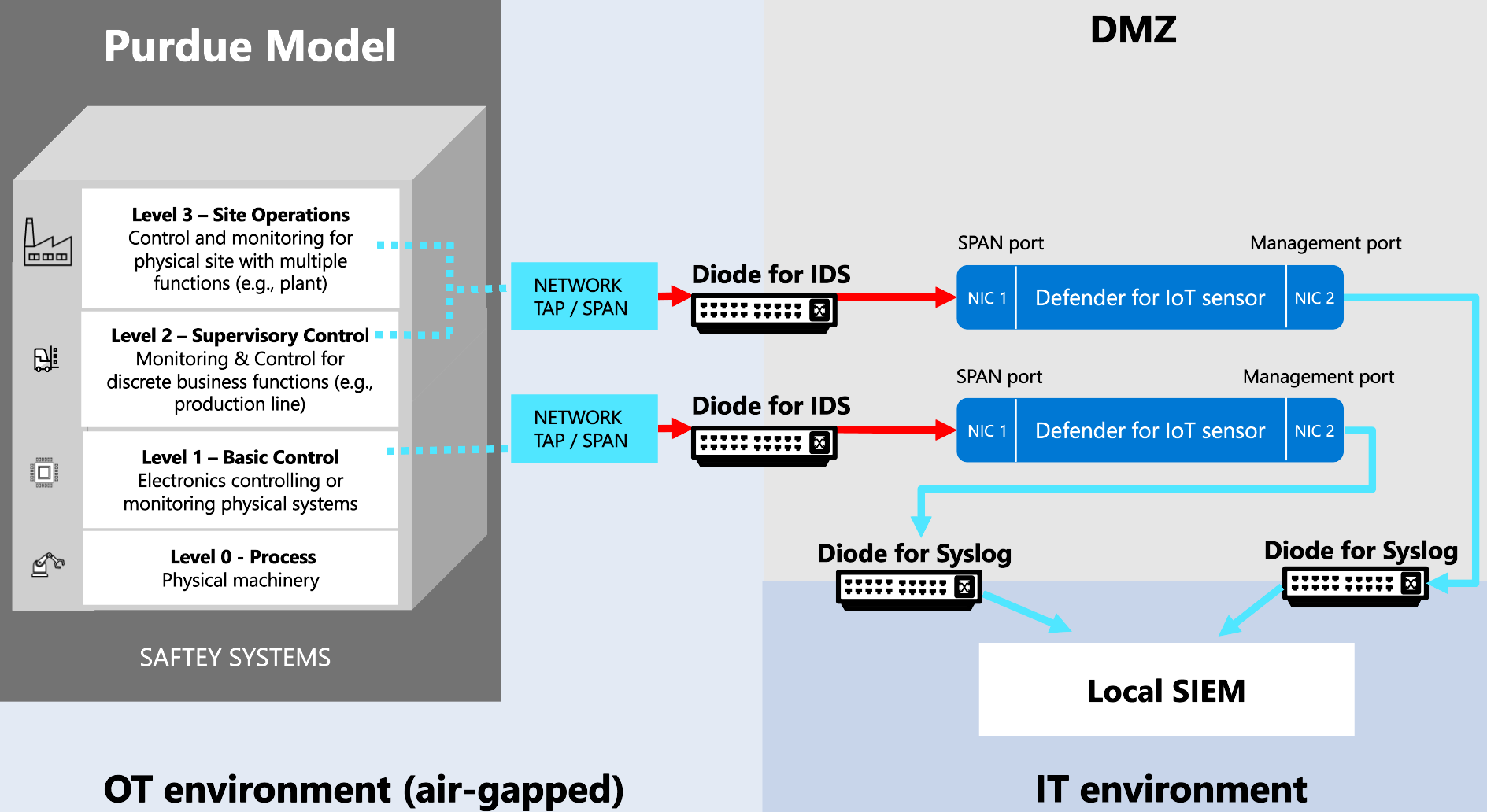
OT sensors placed inside the network perimeter are air-gapped and must be managed locally. They can't connect to the cloud or be managed from the Azure portal. For example, you'll need to manually update these sensors with new threat intelligence packages.
If you're working with a unidirectional network and need cloud-connected sensors that are managed from the Azure portal, make sure to place your sensors outside the network perimeter.

