Designing for disaster recovery with ExpressRoute private peering
ExpressRoute is designed for high availability to provide carrier grade private network connectivity to Microsoft resources. In other words, there's no single point of failure in the ExpressRoute path within Microsoft network. For design considerations to maximize the availability of an ExpressRoute circuit, see Designing for high availability with ExpressRoute and Well-Architectured Framework
However, taking Murphy's popular adage--if anything can go wrong, it will--into consideration, in this article let us focus on solutions that go beyond failures that can be addressed using a single ExpressRoute circuit. We'll look into network architecture considerations for building a robust backend network connectivity for disaster recovery using geo-redundant ExpressRoute circuits.
Note
The concepts described in this article equally applies when an ExpressRoute circuit is created under Virtual WAN or outside of it.
Need for redundant connectivity solution
There are possibilities and instances where an ExpressRoute peering locations or an entire regional service gets degraded. The root cause for such regional wide service outage include natural calamity. Therefore it's important to plan for disaster recovery for business continuity and mission critical applications.
Note
When you need to implement a disaster recovery design in a time-sensitive situation, such as to maintain business continuity during a natural disaster, you should take into account the following factors:
- This document provides guidance on how to implement a robust disaster recovery design for multiple ExpressRoute circuits that are configured through different peering locations. This scenario assumes that you have sufficient time and resources to set up the ExpressRoute circuits.
- If you need to quickly configure a disaster recovery design for a single ExpressRoute circuit that is not geo-redundant, you can use the following alternatives:
- Use a site-to-site VPN as a backup for private peering traffic.
- Use Internet connectivity as a backup for Microsoft peering traffic.
No matter what, whether you run your mission critical applications in an Azure region or on-premises or anywhere else, you can use another Azure region as your failover site. The following articles addresses disaster recovery from applications and frontend access perspectives:
If you rely on ExpressRoute connectivity between your on-premises network and Microsoft, you need to consider the following to plan for disaster recovery over ExpressRoute:
- using geo-redundant ExpressRoute circuits
- using diverse service provider network(s) for different ExpressRoute circuit
- designing each of the ExpressRoute circuit for high availability
- terminating the different ExpressRoute circuit in different location on the customer network
- using Availability zone aware ExpressRoute Virtual Network Gateways
Challenges of using multiple ExpressRoute circuits
When you interconnect the same set of networks using more than one connection, you introduce parallel paths between the networks. Parallel paths, when not properly architected, could lead to asymmetrical routing. If you have stateful entities, for example, a NAT or firewall in the path, asymmetrical routing could block traffic flow. Typically, over the ExpressRoute private peering path you don't come across stateful entities such as NAT or Firewalls. Therefore, asymmetrical routing over ExpressRoute private peering doesn't necessarily block traffic flow.
However, if you load balance traffic across geo-redundant parallel paths, regardless of whether you have stateful entities or not, you would experience inconsistent network performance. These geo-redundant parallel paths can be through the same metro or different metro found on the providers by location page.
Redundancy with ExpressRoute circuits in same metro
Many metros have two ExpressRoute locations. An example would be Amsterdam and Amsterdam2. When designing redundancy, you could build two parallel paths to Azure with both locations in the same metro. You accomplish this task with the same provider or choose to work with a different service provider to improve resiliency. Another advantage of this design is when application failover happens, end-to-end latency between your on-premises applications and Microsoft stays approximately the same. However, if there's a natural disaster such as an earthquake, connectivity for both paths may no longer be available.
Redundancy with ExpressRoute circuits in different metros
When using different metros for redundancy, you should select the secondary location in the same geo-political region. To choose a location outside of the geo-political region, you need to use Premium SKU for both circuits in the parallel paths. The advantage of this configuration is the chances of a natural disaster causing an outage to both links are lower but at the cost of increased latency end-to-end.
Note
Enabling BFD on the ExpressRoute circuits will help with faster link failure detection between Microsoft Enterprise Edge (MSEE) devices and the Customer/Partner Edge routers. However, the overall failover and convergence to redundant site may take up to 180 seconds under some failure conditions and you may experience increased latency or performance degradation during this time.
In this article, let's discuss how to address challenges you may face when configuring geo-redundant paths.
Small to medium on-premises network considerations
Let's consider the example network illustrated in the following diagram. In the example, geo-redundant ExpressRoute connectivity is established between a Contoso's on-premises location and Contoso's VNet in an Azure region. In the diagram, solid blue line indicates preferred path (via ExpressRoute 1) and the dotted one represents stand-by path (via ExpressRoute 2).
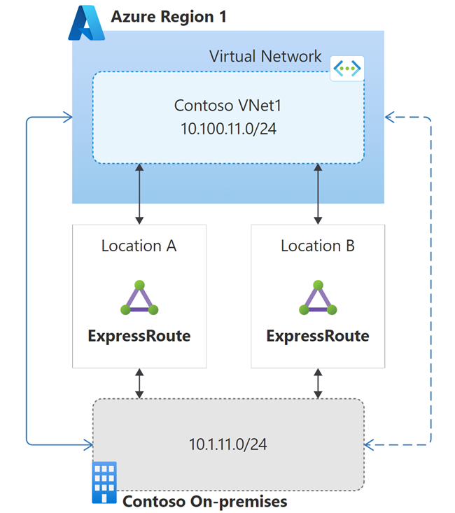
By default, if you advertise routes identically over all the ExpressRoute paths, Azure load-balances on-premises bound traffic across all the ExpressRoute paths using Equal-cost multi-path (ECMP) routing.
However, with the geo-redundant ExpressRoute circuits we need to take into consideration different network performances with different network paths (particularly for network latency). To get more consistent network performance during normal operation, you may want to prefer the ExpressRoute circuit that offers the minimal latency.
You can influence Azure to prefer one ExpressRoute circuit over another one using one of the following techniques (listed in the order of effectiveness):
- advertising more specific route over the preferred ExpressRoute circuit compared to other ExpressRoute circuit(s)
- configuring higher Connection Weight on the connection that links the virtual network to the preferred ExpressRoute circuit
- advertising the routes over less preferred ExpressRoute circuit with longer AS Path (AS Path prepend)
More specific route
The following diagram illustrates influencing ExpressRoute path selection using more specific route advertisement. In the illustrated example, Contoso on-premises /24 IP range is advertised as two /25 address ranges via the preferred path (ExpressRoute 1) and as /24 via the stand-by path (ExpressRoute 2).
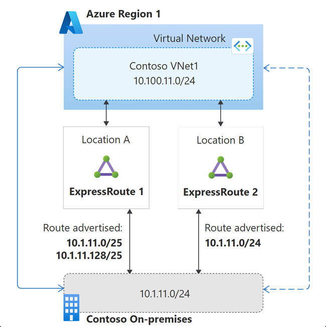
Because /25 is more specific, compared to /24, Azure would send the traffic destined to 10.1.11.0/24 via ExpressRoute 1 in the normal state. If both the connections of ExpressRoute 1 go down, then the VNet would see the 10.1.11.0/24 route advertisement only via ExpressRoute 2; and therefore the standby circuit is used in this failure state.
Connection weight
The following screenshot illustrates configuring the weight of an ExpressRoute connection via Azure portal.
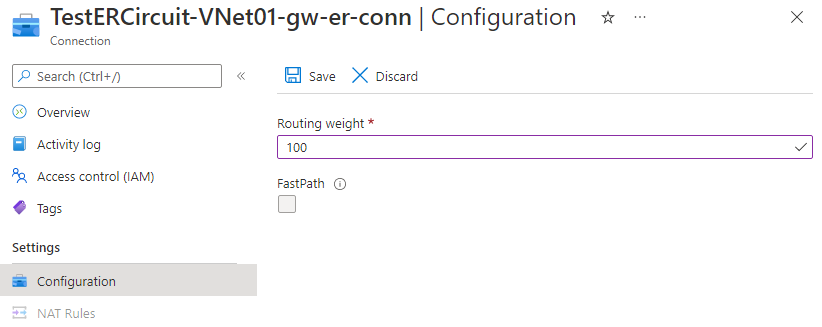
The following diagram illustrates influencing ExpressRoute path selection using connection weight. The default connection weight is 0. In the following example, the weight of the connection for ExpressRoute 1 is configured as 100. When a VNet receives a route prefix advertised via more than one ExpressRoute circuit, the VNet prefers the connection with the highest weight.
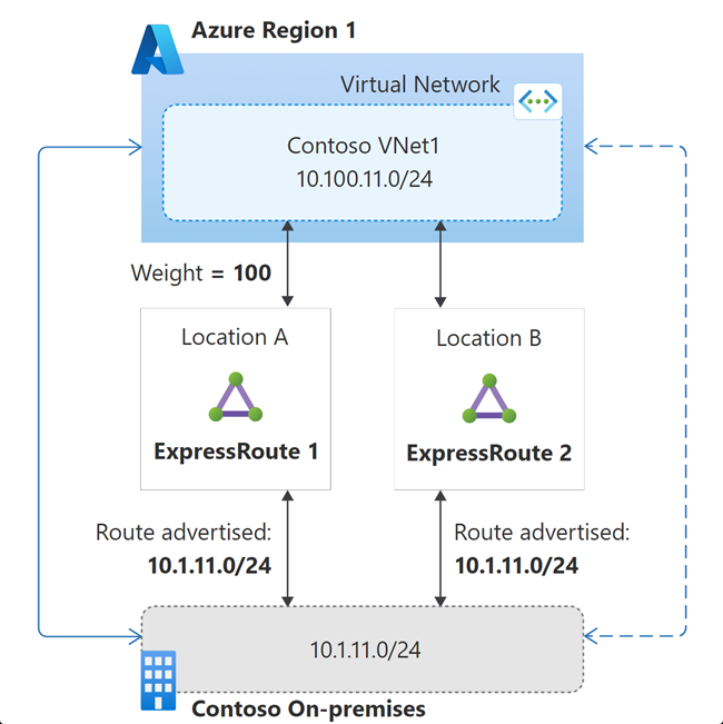
If both the connections of ExpressRoute 1 go down, then the VNet would see the 10.1.11.0/24 route advertisement only via ExpressRoute 2; and therefore the standby circuit is used in this failure state.
AS path prepend
The following diagram illustrates influencing ExpressRoute path selection using AS path prepend. In the diagram, the route advertisement over ExpressRoute 1 indicates the default behavior of eBGP. On the route advertisement over ExpressRoute 2, the on-premises network's ASN is prepended additionally on the route's AS path. When the same route is received through multiple ExpressRoute circuits, per the eBGP route selection process, VNet would prefer the route with the shortest AS path.
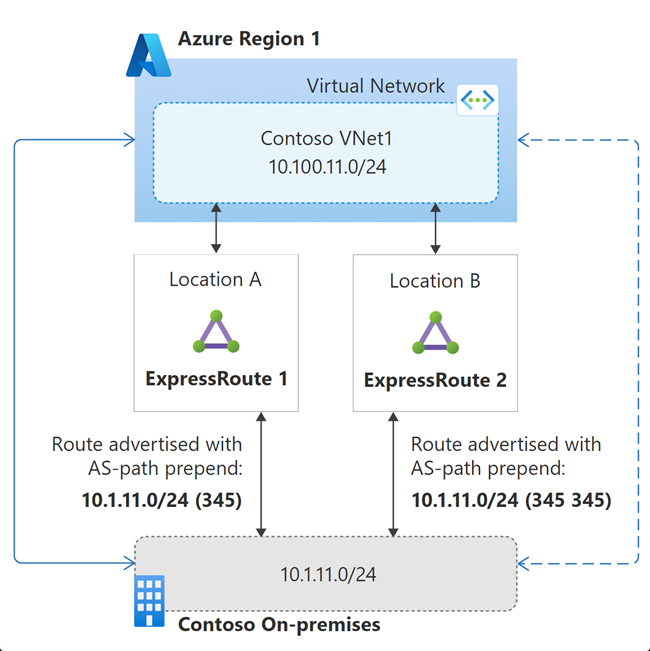
If both the connections of ExpressRoute 1 go down, then the VNet would see the 10.1.11.0/24 route advertisement only via ExpressRoute 2. Consequentially, the longer AS path would become irrelevant. Therefore, the standby circuit would be used in this failure state.
Using any of the techniques, if you influence Azure to prefer one of your ExpressRoute over others, you also need to ensure the on-premises network also prefer the same ExpressRoute path for Azure bound traffic to avoid asymmetric flows. Typically, local preference value is used to influence on-premises network to prefer one ExpressRoute circuit over others. Local preference is an internal BGP (iBGP) metric. The BGP route with the highest local preference value is preferred.
Important
When you use certain ExpressRoute circuits as stand-by, you need to actively manage them and periodically test failover operation.
Large distributed enterprise network
When you have a large distributed enterprise network, you're likely to have multiple ExpressRoute circuits. In this section, let's see how to design disaster recovery using the active-active ExpressRoute circuits, without needing another stand-by circuits.
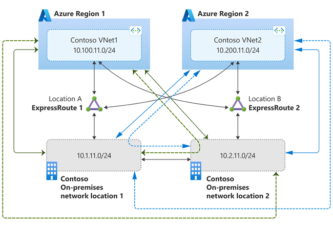
Let's consider the example illustrated in the following diagram. In the example, Contoso has two on-premises locations connected to two Contoso IaaS deployment in two different Azure regions via ExpressRoute circuits in two different peering locations.
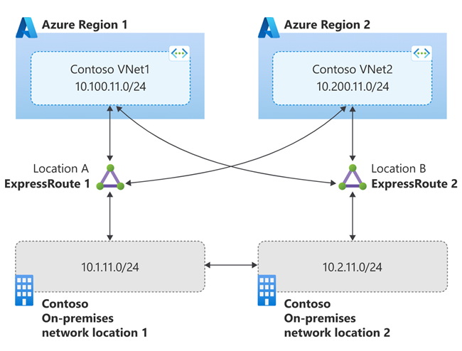
How we architect the disaster recovery has an effect on how cross-regional to cross location (region1/region2 to location2/location1) traffic is routed. Let's consider two different disaster architectures that routes cross region-location traffic differently.
Scenario 1
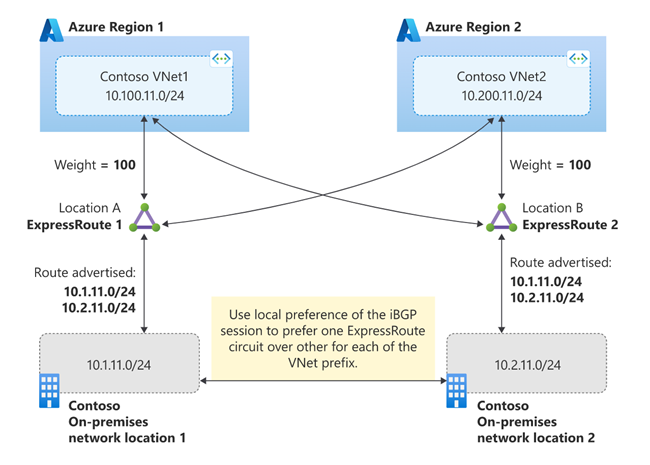
In the first scenario, let's design disaster recovery such that all the traffic between an Azure region and on-premises network flow through the local ExpressRoute circuit in the steady state. If the local ExpressRoute circuit fails, then the remote ExpressRoute circuit is used for all the traffic flows between Azure and on-premises network.
Scenario 1 is illustrated in the following diagram. In the diagram, green lines indicate paths for traffic flow between VNet1 and on-premises networks. The blue lines indicate paths for traffic flow between VNet2 and on-premises networks. Solid lines indicate desired path in the steady-state and the dashed lines indicate traffic path in the failure of the corresponding ExpressRoute circuit that carries steady-state traffic flow.
You can architect the scenario using connection weight to influence VNets to prefer connection to local peering location ExpressRoute for on-premises network bound traffic. To complete the solution, you need to ensure symmetrical reverse traffic flow. You can use local preference on the iBGP session between your BGP routers (on which ExpressRoute circuits are terminated on on-premises side) to prefer a ExpressRoute circuit. The solution is illustrated in the following diagram.
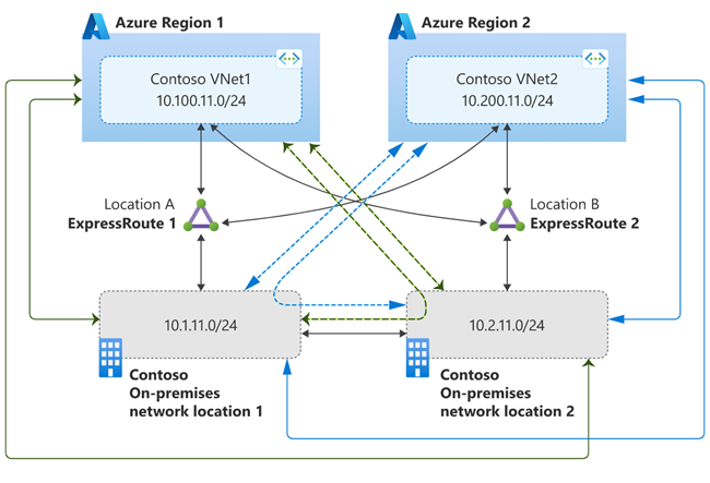
Scenario 2
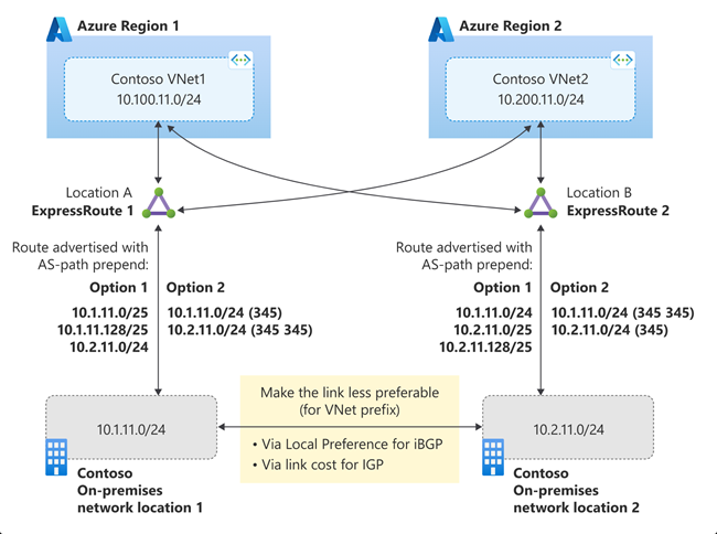
The Scenario 2 is illustrated in the following diagram. In the diagram, green lines indicate paths for traffic flow between VNet1 and on-premises networks. The blue lines indicate paths for traffic flow between VNet2 and on-premises networks. In the steady-state, solid lines in the diagram, all the traffic between VNets and on-premises locations flow using the Microsoft backbone normally, and flows through the interconnection between on-premises locations only in the failure state, dotted lines in the diagram, of an ExpressRoute.
The solution is illustrated in the following diagram. As illustrated, you can architect the scenario either using more specific route (Option 1) or AS-path prepend (Option 2) to influence VNet path selection. To influence on-premises network route selection for Azure bound traffic, you need configure the interconnection between the on-premises location as less preferable. How you configure the interconnection link as preferable depends on the routing protocol used within the on-premises network. You can use local preference with iBGP or metric with IGP (OSPF or IS-IS).
Important
When one or multiple ExpressRoute circuits are connected to multiple virtual networks, virtual network to virtual network traffic can route via ExpressRoute. However, this is not recommended. To enable virtual network to virtual network connectivity, configure virtual network peering.
Next steps
In this article, we discussed how to design for disaster recovery of an ExpressRoute circuit private peering connectivity. The following articles addresses disaster recovery from applications and frontend access perspectives:
Feedback
Coming soon: Throughout 2024 we will be phasing out GitHub Issues as the feedback mechanism for content and replacing it with a new feedback system. For more information see: https://aka.ms/ContentUserFeedback.
Submit and view feedback for