Note
Access to this page requires authorization. You can try signing in or changing directories.
Access to this page requires authorization. You can try changing directories.
An analog-to-digital converter (ADC) is a device that can read an analog input voltage value and convert it into a digital value. ADCs are used for reading values from thermistors, potentiometers, and other devices that change resistance based on certain conditions.
In this topic, you will use .NET to read values from an ADC as you modulate the input voltage with a potentiometer.
Prerequisites
- ARM-based (ARMv7 or greater) single-board computer (SBC)
- MCP3008 analog-to-digital converter
- Three-pin potentiometer
- Breadboard
- Jumper wires
- Raspberry Pi GPIO breakout board (optional/recommended)
- .NET SDK 8 or later
Note
This tutorial is written assuming the target device is Raspberry Pi. However, this tutorial can be used for any Linux-based SBC that supports .NET, such as Orange Pi, ODROID, and more.
Prepare the SBC
Ensure your SBC is configured to support the following services:
- SSH
- SPI
For many devices, no additional configuration is required. For Raspberry Pi, use the raspi-config command. For more information on raspi-config, refer to the Raspberry Pi documentation.
Prepare the hardware
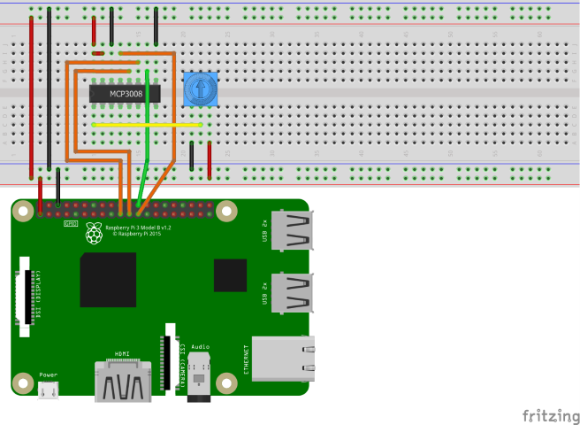
Use the hardware components to build the circuit as depicted in the following diagram:
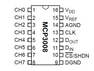
The MCP3008 uses Serial Peripheral Interface (SPI) to communicate. The following are the connections from the MCP3008 to the Raspberry Pi and potentiometer:
- VDD to 3.3V (shown in red)
- VREF to 3.3V (red)
- AGND to ground (black)
- CLK to SCLK (orange)
- DOUT to MISO (orange)
- DIN to MOSI (orange)
- CS/SHDN to CE0 (green)
- DGND to ground (black)
- CH0 to variable (middle) pin on potentiometer (yellow)
Supply 3.3V and ground to the outer pins on the potentiometer. Order is unimportant.
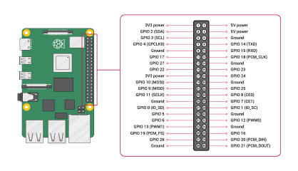
Refer to the following pinout diagrams as needed:
| MCP3008 | Raspberry Pi GPIO |
|---|---|

|

Image courtesy Raspberry Pi Foundation. |
Tip
A GPIO breakout board in conjunction with a breadboard is recommended to streamline connections to the GPIO header.
Create the app
Complete the following steps in your preferred development environment:
Create a new .NET Console App using either the .NET CLI or Visual Studio. Name it AdcTutorial.
dotnet new console -o AdcTutorial
cd AdcTutorial
Add the Iot.Device.Bindings package to the project. Use either .NET CLI from the project directory or Visual Studio.
dotnet add package Iot.Device.Bindings --version 3.2.0-*Replace the contents of Program.cs with the following code:
using System;
using System.Device.Spi;
using System.Threading;
using Iot.Device.Adc;

var hardwareSpiSettings = new SpiConnectionSettings(0, 0);

using SpiDevice spi = SpiDevice.Create(hardwareSpiSettings);
using var mcp = new Mcp3008(spi);
while (true)
{
    Console.Clear();
    double value = mcp.Read(0);
    Console.WriteLine($"{value}");
    Console.WriteLine($"{Math.Round(value/10.23, 1)}%");
    Thread.Sleep(500);
}
In the preceding code:
hardwareSpiSettingsis set to a new instance ofSpiConnectionSettings. The constructor sets thebusIdparameter to 0 and thechipSelectLineparameter to 0.- A using declaration creates an instance of
SpiDeviceby callingSpiDevice.Createand passing inhardwareSpiSettings. ThisSpiDevicerepresents the SPI bus. Theusingdeclaration ensures the object is disposed and hardware resources are released properly. - Another
usingdeclaration creates an instance ofMcp3008and passes theSpiDeviceinto the constructor. - A
whileloop runs indefinitely. Each iteration:- Clears the console.
- Reads the value of CH0 on the ADC by calling
mcp.Read(0). - Writes the raw value to the console.
- Writes the value to the console formatted as a percentage.
- To calculate the percentage, the value is divided by 10.23. The MCP3008 is a 10-bit ADC, which means it returns 1024 possible values ranging 0-1023. Dividing the value by 10.23 represents the value as a percentage.
- The percentage is rounded to the nearest 0.1.
- Sleeps 500 ms.
Build the app. If using the .NET CLI, run
dotnet build. To build in Visual Studio, press Ctrl+Shift+B.Deploy the app to the SBC as a self-contained app. For instructions, see Deploy .NET apps to Raspberry Pi. Make sure to give the executable execute permission using
chmod +x.Run the app on the Raspberry Pi by switching to the deployment directory and running the executable.
./AdcTutorialObserve the output as you rotate the potentiometer dial. This is due to the potentiometer varying the voltage supplied to CH0 on the ADC. The ADC compares the input voltage on CH0 to the reference voltage supplied to VREF to generate a value.
Terminate the program by pressing Ctrl+C.
Congratulations! You've used SPI to read values from an analog-to-digital converter.
Get the source code
The source for this tutorial is available on GitHub.

