Draw graphical objects
 Browse the sample
.NET Multi-platform App UI (.NET MAUI) graphics, in the Microsoft.Maui.Graphics namespace, enables you to draw graphical objects on a canvas that's defined as an ICanvas object.
The .NET MAUI GraphicsView control provides access to an ICanvas object, on which properties can be set and methods invoked to draw graphical objects. For more information about the GraphicsView, see GraphicsView.
Note
Many of the graphical objects have Draw and Fill methods, for example DrawRectangle and FillRectangle. A Draw method draws the outline of the shape, which is unfilled. A Fill method draws the outline of the shape and also fills it.
Graphical objects are drawn on an ICanvas using a device-independent unit that's recognized by each platform. This ensures that graphical objects are scaled appropriately to the pixel density of the underlying platform.
Draw a line
Lines can be drawn on an ICanvas using the DrawLine method, which requires four float arguments that represent the start and end points of the line.
The following example shows how to draw a line:
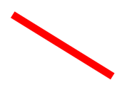
canvas.StrokeColor = Colors.Red;
canvas.StrokeSize = 6;
canvas.DrawLine(10, 10, 90, 100);
In this example, a red diagonal line is drawn from (10,10) to (90,100):
The following example shows how to draw a dashed line:
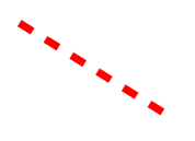
canvas.StrokeColor = Colors.Red;
canvas.StrokeSize = 4;
canvas.StrokeDashPattern = new float[] { 2, 2 };
canvas.DrawLine(10, 10, 90, 100);
In this example, a red dashed diagonal line is drawn from (10,10) to (90,100):
For more information about dashed lines, see Draw dashed objects.
Draw an ellipse
Ellipses and circles can be drawn on an ICanvas using the DrawEllipse method, which requires x, y, width, and height arguments, of type float.
The following example shows how to draw an ellipse:
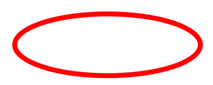
canvas.StrokeColor = Colors.Red;
canvas.StrokeSize = 4;
canvas.DrawEllipse(10, 10, 100, 50);
In this example, a red ellipse with dimensions 100x50 is drawn at (10,10):
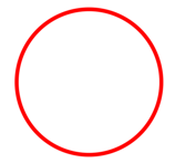
To draw a circle, make the width and height arguments to the DrawEllipse method equal:
canvas.StrokeColor = Colors.Red;
canvas.StrokeSize = 4;
canvas.DrawEllipse(10, 10, 100, 100);
In this example, a red circle with dimensions 100x100 is drawn at (10,10):
Note
Circles can also be drawn with the DrawCircle method.
For information about drawing a dashed ellipse, see Draw dashed objects.
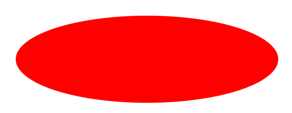
A filled ellipse can be drawn with the FillEllipse method, which also requires x, y, width, and height arguments, of type float:
canvas.FillColor = Colors.Red;
canvas.FillEllipse(10, 10, 150, 50);
In this example, a red filled ellipse with dimensions 150x50 is drawn at (10,10):
The FillColor property of the ICanvas object must be set to a Color before invoking the FillEllipse method.
Filled circles can also be drawn with the FillCircle method.
Note
There are DrawEllipse and FillEllipse overloads that take Rect and RectF arguments. In addition, there are also DrawCircle and FillCircle overloads.
Draw a rectangle
Rectangles and squares can be drawn on an ICanvas using the DrawRectangle method, which requires x, y, width, and height arguments, of type float.
The following example shows how to draw a rectangle:
canvas.StrokeColor = Colors.DarkBlue;
canvas.StrokeSize = 4;
canvas.DrawRectangle(10, 10, 100, 50);
In this example, a dark blue rectangle with dimensions 100x50 is drawn at (10,10):

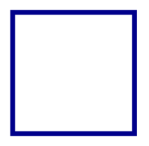
To draw a square, make the width and height arguments to the DrawRectangle method equal:
canvas.StrokeColor = Colors.DarkBlue;
canvas.StrokeSize = 4;
canvas.DrawRectangle(10, 10, 100, 100);
In this example, a dark blue square with dimensions 100x100 is drawn at (10,10):
For information about drawing a dashed rectangle, see Draw dashed objects.
A filled rectangle can be drawn with the FillRectangle method, which also requires x, y, width, and height arguments, of type float:
canvas.FillColor = Colors.DarkBlue;
canvas.FillRectangle(10, 10, 100, 50);
In this example, a dark blue filled rectangle with dimensions 100x50 is drawn at (10,10):

The FillColor property of the ICanvas object must be set to a Color before invoking the FillRectangle method.
Note
There are DrawRectangle and FillRectangle overloads that take Rect and RectF arguments.
Draw a rounded rectangle
Rounded rectangles and squares can be drawn on an ICanvas using the DrawRoundedRectangle method, which requires x, y, width, height, and cornerRadius arguments, of type float. The cornerRadius argument specifies the radius used to round the corners of the rectangle.
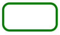
The following example shows how to draw a rounded rectangle:
canvas.StrokeColor = Colors.Green;
canvas.StrokeSize = 4;
canvas.DrawRoundedRectangle(10, 10, 100, 50, 12);
In this example, a green rectangle with rounded corners and dimensions 100x50 is drawn at (10,10):
For information about drawing a dashed rounded rectangle, see Draw dashed objects.
A filled rounded rectangle can be drawn with the FillRoundedRectangle method, which also requires x, y, width, height, and cornerRadius arguments, of type float:
canvas.FillColor = Colors.Green;
canvas.FillRoundedRectangle(10, 10, 100, 50, 12);
In this example, a green filled rectangle with rounded corners and dimensions 100x50 is drawn at (10,10):

The FillColor property of the ICanvas object must be set to a Color before invoking the FillRoundedRectangle method.
Note
There are DrawRoundedRectangle and FillRoundedRectangle overloads that take Rect and RectF arguments, and overloads that enable the radius of each corner to be separately specified.
Draw an arc
Arcs can be drawn on an ICanvas using the DrawArc method, which requires x, y, width, height, startAngle, and endAngle arguments of type float, and clockwise and closed arguments of type bool. The startAngle argument specifies the angle from the x-axis to the starting point of the arc. The endAngle argument specifies the angle from the x-axis to the end point of the arc. The clockwise argument specifies the direction in which the arc is drawn, and the closed argument specifies whether the end point of the arc will be connected to the start point.
The following example shows how to draw an arc:
canvas.StrokeColor = Colors.Teal;
canvas.StrokeSize = 4;
canvas.DrawArc(10, 10, 100, 100, 0, 180, true, false);
In this example, a teal arc of dimensions 100x100 is drawn at (10,10). The arc is drawn in a clockwise direction from 0 degrees to 180 degrees, and isn't closed:

For information about drawing a dashed arc, see Draw dashed objects.
A filled arc can be drawn with the FillArc method, which requires x, y, width, height, startAngle, and endAngle arguments of type float, and a clockwise argument of type bool:
canvas.FillColor = Colors.Teal;
canvas.FillArc(10, 10, 100, 100, 0, 180, true);
In this example, a filled teal arc of dimensions 100x100 is drawn at (10,10). The arc is drawn in a clockwise direction from 0 degrees to 180 degrees, and is closed automatically:

The FillColor property of the ICanvas object must be set to a Color before invoking the FillArc method.
Draw a path
A path is a collection of one or more contours. Each contour is a collection of connected straight lines and curves. Contours are not connected to each other but they might visually overlap. Sometimes a single contour can overlap itself.
Paths are used to draw curves and complex shapes and can be drawn on an ICanvas using the DrawPath method, which requires a PathF argument.
A contour generally begins with a call to the PathF.MoveTo method, which you can express either as a PointF value or as separate x and y coordinates. The MoveTo call establishes a point at the beginning of the contour and an initial current point. You can then call the following methods to continue the contour with a line or curve from the current point to a point specified in the method, which then becomes the new current point:
- LineTo to add a straight line to the path.
- AddArc to add an arc, which is a line on the circumference of a circle or ellipse.
- CurveTo to add a cubic Bezier spline.
- QuadTo to add a quadratic Bezier spline.
None of these methods contain all of the data necessary to describe the line or curve. Instead, each method works with the current point established by the method call immediately preceding it. For example, the LineTo method adds a straight line to the contour based on the current point.
A contour ends with another call to MoveTo, which begins a new contour, or a call to Close, which closes the contour. The Close method automatically appends a straight line from the current point to the first point of the contour, and marks the path as closed.
The PathF class also defines other methods and properties. The following methods add entire contours to the path:
- AppendEllipse appends a closed ellipse contour to the path.
- AppendCircle appends a closed circle contour to the path.
- AppendRectangle appends a closed rectangle contour to the path.
- AppendRoundedRectangle appends a closed rectangle with rounded corners to the path.
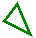
The following example shows how to draw a path:
PathF path = new PathF();
path.MoveTo(40, 10);
path.LineTo(70, 80);
path.LineTo(10, 50);
path.Close();
canvas.StrokeColor = Colors.Green;
canvas.StrokeSize = 6;
canvas.DrawPath(path);
In this example, a closed green triangle is drawn:
A filled path can be drawn with the FillPath, which also requires a PathF argument:
PathF path = new PathF();
path.MoveTo(40, 10);
path.LineTo(70, 80);
path.LineTo(10, 50);
canvas.FillColor = Colors.SlateBlue;
canvas.FillPath(path);
In this example, a filled slate blue triangle is drawn:

The FillColor property of the ICanvas object must be set to a Color before invoking the FillPath method.
Important
The FillPath method has an overload that enables a WindingMode to be specified, which sets the fill algorithm that's used. For more information, see Winding modes.
Draw an image
Images can be drawn on an ICanvas using the DrawImage method, which requires an IImage argument, and x, y, width, and height arguments, of type float.
The following example shows how to load an image and draw it to the canvas:
using System.Reflection;
using IImage = Microsoft.Maui.Graphics.IImage;
#if IOS || ANDROID || MACCATALYST
using Microsoft.Maui.Graphics.Platform;
#elif WINDOWS
using Microsoft.Maui.Graphics.Win2D;
#endif

IImage image;
Assembly assembly = GetType().GetTypeInfo().Assembly;
using (Stream stream = assembly.GetManifestResourceStream("GraphicsViewDemos.Resources.Images.dotnet_bot.png"))
{
#if IOS || ANDROID || MACCATALYST
    // PlatformImage isn't currently supported on Windows.
    image = PlatformImage.FromStream(stream);
#elif WINDOWS
    image = new W2DImageLoadingService().FromStream(stream);
#endif
}

if (image != null)
{
    canvas.DrawImage(image, 10, 10, image.Width, image.Height);
}
using System.Reflection;
using IImage = Microsoft.Maui.Graphics.IImage;
using Microsoft.Maui.Graphics.Platform;

IImage image;
Assembly assembly = GetType().GetTypeInfo().Assembly;
using (Stream stream = assembly.GetManifestResourceStream("GraphicsViewDemos.Resources.Images.dotnet_bot.png"))
{
    image = PlatformImage.FromStream(stream);
}

if (image != null)
{
    canvas.DrawImage(image, 10, 10, image.Width, image.Height);
}
In this example, an image is retrieved from the assembly and loaded as a stream. It's then drawn at actual size at (10,10):

Important
Loading an image that's embedded in an assembly requires the image to have its build action set to Embedded Resource rather than MauiImage.
Draw a string
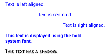
Strings can be drawn on an ICanvas using one of the DrawString overloads. The appearance of each string can be defined by setting the Font, FontColor, and FontSize properties. String alignment can be specified by horizontal and vertical alignment options that perform alignment within the string's bounding box.
Note
The bounding box for a string is defined by its x, y, width, and height arguments.
The following examples show how to draw strings:
canvas.FontColor = Colors.Blue;
canvas.FontSize = 18;

canvas.Font = Font.Default;
canvas.DrawString("Text is left aligned.", 20, 20, 380, 100, HorizontalAlignment.Left, VerticalAlignment.Top);
canvas.DrawString("Text is centered.", 20, 60, 380, 100, HorizontalAlignment.Center, VerticalAlignment.Top);
canvas.DrawString("Text is right aligned.", 20, 100, 380, 100, HorizontalAlignment.Right, VerticalAlignment.Top);

canvas.Font = Font.DefaultBold;
canvas.DrawString("This text is displayed using the bold system font.", 20, 140, 350, 100, HorizontalAlignment.Left, VerticalAlignment.Top);

canvas.Font = new Font("Arial");
canvas.FontColor = Colors.Black;
canvas.SetShadow(new SizeF(6, 6), 4, Colors.Gray);
canvas.DrawString("This text has a shadow.", 20, 200, 300, 100, HorizontalAlignment.Left, VerticalAlignment.Top);
In this example, strings with different appearance and alignment options are displayed:
Note
The DrawString overloads also enable truncation and line spacing to be specified.
For information about drawing shadows, see Draw a shadow.
Draw attributed text
Attributed text can be drawn on an ICanvas using the DrawText method, which requires an IAttributedText argument, and x, y, width, and height arguments, of type float. Attributed text is a string with associated attributes for parts of its text, that typically represents styling data.
The following example shows how to draw attributed text:
using Microsoft.Maui.Graphics.Text;
...

canvas.Font = new Font("Arial");
canvas.FontSize = 18;
canvas.FontColor = Colors.Blue;

string markdownText = @"This is *italic text*, **bold text**, __underline text__, and ***bold italic text***.";
IAttributedText attributedText = MarkdownAttributedTextReader.Read(markdownText); // Requires the Microsoft.Maui.Graphics.Text.Markdig package
canvas.DrawText(attributedText, 10, 10, 400, 400);
In this example, markdown is converted to attributed text and displayed with the correct styling:

Important
Drawing attributed text requires you to have added the Microsoft.Maui.Graphics.Text.Markdig NuGet package to your project.
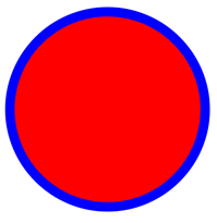
Draw with fill and stroke
Graphical objects with both fill and stroke can be drawn to the canvas by calling a draw method after a fill method. For example, to draw an outlined rectangle, set the FillColor and StrokeColor properties to colors, then call the FillRectangle method followed by the DrawRectangle method.
The following example draws a filled circle, with a stroke outline, as a path:
float radius = Math.Min(dirtyRect.Width, dirtyRect.Height) / 4;

PathF path = new PathF();
path.AppendCircle(dirtyRect.Center.X, dirtyRect.Center.Y, radius);

canvas.StrokeColor = Colors.Blue;
canvas.StrokeSize = 10;
canvas.FillColor = Colors.Red;

canvas.FillPath(path);
canvas.DrawPath(path);
In this example, the stroke and fill colors for a PathF object are specified. The filled circle is drawn, then the outline stroke of the circle:
Warning
Calling a draw method before a fill method will result in an incorrect z-order. The fill will be drawn over the stroke, and the stroke won't be visible.
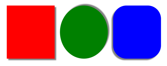
Draw a shadow
Graphical objects drawn on an ICanvas can have a shadow applied using the SetShadow method, which takes the following arguments:
offset, of type SizeF, specifies an offset for the shadow, which represents the position of a light source that creates the shadow.blur, of typefloat, represents the amount of blur to apply to the shadow.color, of type Color, defines the color of the shadow.
The following examples show how to add shadows to filled objects:
canvas.FillColor = Colors.Red;
canvas.SetShadow(new SizeF(10, 10), 4, Colors.Grey);
canvas.FillRectangle(10, 10, 90, 100);

canvas.FillColor = Colors.Green;
canvas.SetShadow(new SizeF(10, -10), 4, Colors.Grey);
canvas.FillEllipse(110, 10, 90, 100);

canvas.FillColor = Colors.Blue;
canvas.SetShadow(new SizeF(-10, 10), 4, Colors.Grey);
canvas.FillRoundedRectangle(210, 10, 90, 100, 25);
In these examples, shadows whose light sources are in different positions are added to the filled objects, with identical amounts of blur:
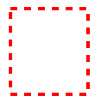
Draw dashed objects
ICanvas objects have a StrokeDashPattern property, of type float[]. This property is an array of float values that indicate the pattern of dashes and gaps that are to be used when drawing the stroke for an object. Each float in the array specifies the length of a dash or gap. The first item in the array specifies the length of a dash, while the second item in the array specifies the length of a gap. Therefore, float values with an even index value specify dashes, while float values with an odd index value specify gaps.
The following example shows how to draw a dashed square, using a regular dash:
canvas.StrokeColor = Colors.Red;
canvas.StrokeSize = 4;
canvas.StrokeDashPattern = new float[] { 2, 2 };
canvas.DrawRectangle(10, 10, 90, 100);
In this example, a square with a regular dashed stroke is drawn:
The following example shows how to draw a dashed square, using an irregular dash:
canvas.StrokeColor = Colors.Red;
canvas.StrokeSize = 4;
canvas.StrokeDashPattern = new float[] { 4, 4, 1, 4 };
canvas.DrawRectangle(10, 10, 90, 100);
In this example, a square with an irregular dashed stroke is drawn:

Control line ends
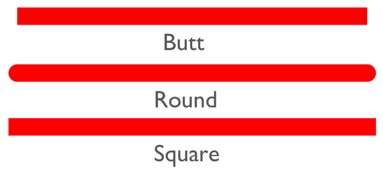
A line has three parts: start cap, line body, and end cap. The start and end caps describe the start and end of a line.
ICanvas objects have a StrokeLineCap property, of type LineCap, that describes the start and end of a line. The LineCap enumeration defines the following members:
Butt, which represents a line with a square end, drawn to extend to the exact endpoint of the line. This is the default value of the StrokeLineCap property.Round, which represents a line with a rounded end.Square, which represents a line with a square end, drawn to extend beyond the endpoint to a distance equal to half the line width.
The following example shows how to set the StrokeLineCap property:
canvas.StrokeSize = 10;
canvas.StrokeColor = Colors.Red;
canvas.StrokeLineCap = LineCap.Round;
canvas.DrawLine(10, 10, 110, 110);
In this example, the red line is rounded at the start and end of the line:
Control line joins
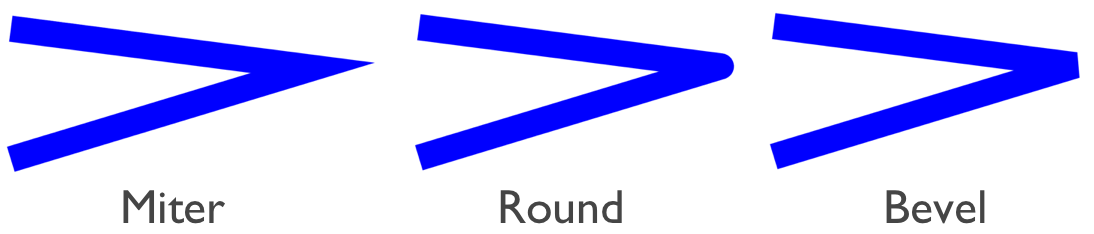
ICanvas objects have a StrokeLineJoin property, of type LineJoin, that specifies the type of join that is used at the vertices of an object. The LineJoin enumeration defines the following members:
Miter, which represents angular vertices that produce a sharp or clipped corner. This is the default value of the StrokeLineJoin property.Round, which represents rounded vertices that produce a circular arc at the corner.Bevel, which represents beveled vertices that produce a diagonal corner.
Note
When the StrokeLineJoin property is set to Miter, the MiterLimit property can be set to a float to limit the miter length of line joins in the object.
The following example shows how to set the StrokeLineJoin property:
PathF path = new PathF();
path.MoveTo(10, 10);
path.LineTo(110, 50);
path.LineTo(10, 110);

canvas.StrokeSize = 20;
canvas.StrokeColor = Colors.Blue;
canvas.StrokeLineJoin = LineJoin.Round;
canvas.DrawPath(path);
In this example, the blue PathF object has rounded joins at its vertices:
Clip objects
Graphical objects that are drawn to an ICanvas can be clipped prior to drawing, with the following methods:
- ClipPath clips an object so that only the area that's within the region of a PathF object will be visible.
- ClipRectangle clips an object so that only the area that's within the region of a rectangle will be visible. The rectangle can be specified using
floatarguments, or by a Rect or RectF argument. - SubtractFromClip clips an object so that only the area that's outside the region of a rectangle will be visible. The rectangle can be specified using
floatarguments, or by a Rect or RectF argument.
The following example shows how to use the ClipPath method to clip an image:
using System.Reflection;
using IImage = Microsoft.Maui.Graphics.IImage;
#if IOS || ANDROID || MACCATALYST
using Microsoft.Maui.Graphics.Platform;
#elif WINDOWS
using Microsoft.Maui.Graphics.Win2D;
#endif

IImage image;
Assembly assembly = GetType().GetTypeInfo().Assembly;
using (Stream stream = assembly.GetManifestResourceStream("GraphicsViewDemos.Resources.Images.dotnet_bot.png"))
{
#if IOS || ANDROID || MACCATALYST
    // PlatformImage isn't currently supported on Windows.
    image = PlatformImage.FromStream(stream);
#elif WINDOWS
    image = new W2DImageLoadingService().FromStream(stream);
#endif
}

if (image != null)
{
    PathF path = new PathF();
    path.AppendCircle(100, 90, 80);
    canvas.ClipPath(path);  // Must be called before DrawImage
    canvas.DrawImage(image, 10, 10, image.Width, image.Height);
}
using System.Reflection;
using IImage = Microsoft.Maui.Graphics.IImage;
using Microsoft.Maui.Graphics.Platform;

IImage image;
Assembly assembly = GetType().GetTypeInfo().Assembly;
using (Stream stream = assembly.GetManifestResourceStream("GraphicsViewDemos.Resources.Images.dotnet_bot.png"))
{
    image = PlatformImage.FromStream(stream);
}

if (image != null)
{
    PathF path = new PathF();
    path.AppendCircle(100, 90, 80);
    canvas.ClipPath(path);  // Must be called before DrawImage
    canvas.DrawImage(image, 10, 10, image.Width, image.Height);
}
In this example, the image is clipped using a PathF object that defines a circle that's centered at (100,90) with a radius of 80. The result is that only the part of the image within the circle is visible:

Important
The ClipPath method has an overload that enables a WindingMode to be specified, which sets the fill algorithm that's used when clipping. For more information, see Winding modes.
The following example shows how to use the SubtractFromClip method to clip an image:
using System.Reflection;
using IImage = Microsoft.Maui.Graphics.IImage;
#if IOS || ANDROID || MACCATALYST
using Microsoft.Maui.Graphics.Platform;
#elif WINDOWS
using Microsoft.Maui.Graphics.Win2D;
#endif

IImage image;
Assembly assembly = GetType().GetTypeInfo().Assembly;
using (Stream stream = assembly.GetManifestResourceStream("GraphicsViewDemos.Resources.Images.dotnet_bot.png"))
{
#if IOS || ANDROID || MACCATALYST
    // PlatformImage isn't currently supported on Windows.
    image = PlatformImage.FromStream(stream);
#elif WINDOWS
    image = new W2DImageLoadingService().FromStream(stream);
#endif
}

if (image != null)
{
    canvas.SubtractFromClip(60, 60, 90, 90);
    canvas.DrawImage(image, 10, 10, image.Width, image.Height);
}
using System.Reflection;
using IImage = Microsoft.Maui.Graphics.IImage;
using Microsoft.Maui.Graphics.Platform;

IImage image;
Assembly assembly = GetType().GetTypeInfo().Assembly;
using (Stream stream = assembly.GetManifestResourceStream("GraphicsViewDemos.Resources.Images.dotnet_bot.png"))
{
    image = PlatformImage.FromStream(stream);
}

if (image != null)
{
    canvas.SubtractFromClip(60, 60, 90, 90);
    canvas.DrawImage(image, 10, 10, image.Width, image.Height);
}
In this example, the area defined by the rectangle that's specified by the arguments supplied to the SubtractFromClip method is clipped from the image. The result is that only the parts of the image outside the rectangle are visible:

Feedback
Coming soon: Throughout 2024 we will be phasing out GitHub Issues as the feedback mechanism for content and replacing it with a new feedback system. For more information see: https://aka.ms/ContentUserFeedback.
Submit and view feedback for