ACX streaming
This topic discusses ACX streaming and the associated buffering, which is critical to a glitch free audio experience. It describes the mechanisms used by the driver to communicate about the stream state and manage the buffer for the stream. For a list of common ACX audio terms and an introduction to ACX, see ACX audio class extensions overview.
ACX streaming types
An AcxStream represents an audio stream on a specific circuit’s hardware. An AcxStream may aggregate one or more AcxElements-like objects.
The ACX framework supports two stream types. The first stream type, the RT Packet Stream, provides support for allocating RT packets and using RT packets for transferring audio data to or from the device hardware along with stream state transitions. The second stream type, the Basic Stream, provides only support for stream state transitions.
In a single circuit endpoint the circuit must be a streaming circuit that creates an RT Packet Stream. If two or more circuits are connected to create an endpoint, the first circuit in the endpoint is the streaming circuit and creates an RT Packet Stream; connected circuits will create Basic Streams to receive events related to stream state transitions.
For more information, see ACX Stream in Summary of ACX Objects. The DDIs for stream are defined in the acxstreams.h header.
ACX streaming communications stack
There are two types of communications for ACX Streaming. One communications path is used for controlling the streaming behavior, for commands such as Start, Create, and Allocate, that will use the standard ACX communications. The ACX framework uses IO Queues and passes along WDF Requests using the queues. The queue behavior is hidden from the actual driver code through the use of Evt callbacks and ACX functions, though the driver is also be given a chance to pre-process all WDF Requests.
The second and more interesting communications path, is used for the audio streaming signaling. This involves telling the driver when a packet is ready and receiving data on when the driver has finished processing a packet.
The main requirements for streaming signaling:
- Support Glitch-Free Playback
- Low Latency
- Any necessary locks are limited to the stream in question
- Ease of use for driver developer
To communicate with the driver to signal streaming state, ACX uses events with a shared buffer and direct IRP calls. These are described next.
Shared buffer
For communicating from the driver to the client, a shared buffer and event are used. This ensures the client does not need to wait or poll, and that the client can determine everything it needs to continue streaming while reducing or eliminating the need for direct IRP calls.
The device driver uses a shared buffer to communicate to the client which packet is being rendered from or captured to. This shared buffer includes the packet count (1-based) of the last completed packet along with the QPC (QueryPerformanceCounter) value of the completion time. For the device driver, it must indicate this information by calling AcxRtStreamNotifyPacketComplete. When the device driver calls AcxRtStreamNotifyPacketComplete, the ACX framework will update the shared buffer with the new packet count and QPC and signal an event shared with the client to indicate that the client may read the new packet count.
Direct IRP calls
For communicating from the client to the driver, direct IRP calls are used. This reduces the complexities around ensuring WDF requests are handled in a timely manner and has been proven to work well in the existing architecture.
The client may at any time request the current packet count or indicate the current packet count to the device driver. These requests will call the EvtAcxStreamGetCurrentPacket and EvtAcxStreamSetRenderPacket device driver event handlers. The client may also request the current capture packet which will call the EvtAcxStreamGetCapturePacket device driver event handler.
Similarities with PortCls
The combination of direct IRP calls and shared buffer used by ACX is similar to how buffer completion handling is communicated in PortCls. The IRPs are very similar and the shared buffer introduces the ability for the driver to directly communicate packet count and timing without relying on IRPs. Drivers will need to ensure they do nothing that requires access to locks that are also used in the stream control paths – this is necessary to prevent glitching.
Large buffer support for low power playback
To reduce the amount of power consumed when playing back media content, it is important to reduce the amount of time the APU spends in a high-power state. Since the normal audio playback uses 10ms buffers, the APU always needs to be active. To give the APU the time it needs to reduce state, ACX drivers are allowed to advertise support for significantly larger buffers, in the 1-2 second size range. This means the APU can wake up once every 1-2 seconds, do the operations required at maximum speed to prepare the next 1-2 second buffer, and then go to the lowest possible power state until the next buffer is needed.
In existing streaming models low power playback is supported through Offload Playback. An audio driver advertises support for Offload Playback by exposing an AudioEngine node on the wave filter for an endpoint. The AudioEngine node provides a means to control the DSP engine the driver uses to render the audio from the large buffers with the desired processing.
The AudioEngine node provides these facilities:
- Audio Engine Description, which tells the audio stack which pins on the wave filter provide offload and loopback support (and host playback support).
- Buffer Size Range, which tells the audio stack the minimum and maximum buffer sizes that can be supported for offload. playback. The Buffer Size Range can change dynamically based on system activity.
- Format support, including supported formats, the current device mix format, and the device format.
- Volume, including ramping support, since with the larger buffers software volume will not be responsive.
- Loopback Protection, which tells the driver to mute the AudioEngine Loopback pin if one or more of the Offloaded streams contains protected content.
- Global FX state, to enable or disable GFX on the AudioEngine.
When a stream is created on the Offload Pin, the stream supports Volume, Local FX, and Loopback Protection.
Low power playback with ACX
The ACX framework uses the same model for low power playback. The driver creates three separate ACXPIN objects for host, offload, and loopback streaming, along with an ACXAUDIOENGINE element that describes which of these pins are used for host, offload, and loopback. The driver adds the pins and ACXAUDIOENGINE element to the ACXCIRCUIT during circuit creation.
Offloaded stream creation
The driver will also add an ACXAUDIOENGINE element to streams created for offload to allow control over volume, mute, and peak meter.
Streaming diagram
This diagram shows a multi-stack ACX driver.
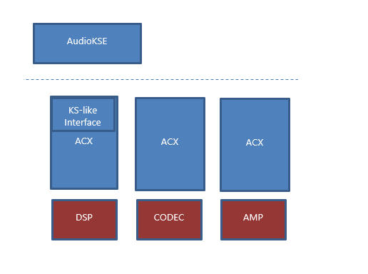
Each ACX driver controls a separate portion of the audio hardware and could be provided by a different vendor. ACX provides a compatible kernel streaming interface to allow applications to run as is.
Stream pins
Each ACXCIRCUIT has at least one Sink Pin and one Source Pin. These Pins are used by the ACX framework to expose the circuit’s connections to the audio stack. For a Render circuit, the Source Pin is used to control the render behavior of any stream created from the circuit. For a Capture circuit, the Sink Pin is used to control the capture behavior of any stream created from the circuit. ACXPIN is the object used to control streaming in the Audio Path. The streaming ACXCIRCUIT is responsible for creating the appropriate ACXPIN object(s) for the Endpoint Audio Path at circuit creation time and registering the ACXPINs with ACX. The ACXCIRCUIT only needs to create the render or capture pin or pins for the Circuit; the ACX framework will create the other pin needed to connect to and communicate with the circuit.
Streaming circuit
When an endpoint is composed of a single circuit, that circuit is the streaming circuit.
When an endpoint is composed of more than one circuit created by one or more device drivers, the circuits are connected in the specific order determined by the ACXCOMPOSITETEMPLATE that describes the composed endpoint. The first circuit in the endpoint is the streaming circuit for the endpoint.
The streaming circuit should use AcxRtStreamCreate to create an RT Packet Stream in response to EvtAcxCircuitCreateStream. The ACXSTREAM created with AcxRtStreamCreate will allow the streaming circuit driver to allocate the buffer used for streaming and to control the streaming flow in response to the client and hardware needs.
Following circuits in the endpoint should use AcxStreamCreate to create a Basic Stream in response to EvtAcxCircuitCreateStream. The ACXSTREAM objects created with AcxStreamCreate by the following circuits will allow the drivers to configure hardware in response to stream state changes such as Pause or Run.
The streaming ACXCIRCUIT is the first circuit to receive the requests to create a stream. The request includes the device, the pin, and the data format (including mode).
Each ACXCIRCUIT in the Audio Path will create an ACXSTREAM object that represents the circuit’s stream instance. The ACX framework links the ACXSTREAM objects together (in much the same way the ACXCIRCUIT objects are linked).
Upstream and downstream circuits
Stream creation starts at the streaming circuit and is forwarded to each downstream circuit in the order the circuits are connected. The connections are made between bridge pins created with Communication equal to AcxPinCommunicationNone. The ACX framework will create one or more bridge pins for a circuit if the driver doesn't add them at circuit creation time.
For each circuit starting with the streaming circuit, the AcxPinTypeSource bridge pin will connect to the next downstream circuit. The final circuit will have an endpoint pin describing the audio endpoint hardware (such as whether the endpoint is a Microphone or Speaker and whether the Jack is plugged in).
For each circuit following the streaming circuit, the AcxPinTypeSink bridge pin will connect to the next upstream circuit.
Stream format negotiation
The driver advertises the supported formats for stream creation by adding the supported formats per mode to the ACXPIN used for stream creation with AcxPinAssignModeDataFormatList and AcxPinGetRawDataFormatList. For multi circuit endpoints, an ACXSTREAMBRIDGE can be used to coordinate mode and format support between ACX Circuits. The supported stream formats for the endpoint are determined by the streaming ACXPINs created by the streaming circuit. The formats used by the following circuits are determined by the bridge pin of the previous circuit in the endpoint.
By default, the ACX framework will create an ACXSTREAMBRIDGE between each circuit in a multi circuit endpoint. The default ACXSTREAMBRIDGE will use the RAW mode's default format of the bridge pin of the upstream circuit when forwarding the stream creation request to the downstream circuit. If the upstream circuit's bridge pin has no formats, the original stream format will be used. If the connected pin of the downstream circuit does not support the format being used, stream creation will fail.
If a device circuit is performing a stream format change, the device driver should add the downstream format to the downstream bridge pin.
Stream creation
The first step in Stream Creation is creating the ACXSTREAM instance for each ACXCIRCUIT in the Endpoint Audio Path. ACX will call each circuit’s EvtAcxCircuitCreateStream. ACX will start with the head circuit and call each circuit’s EvtAcxCircuitCreateStream in order, ending with the tail circuit. The order can be reversed by specifying the AcxStreamBridgeInvertChangeStateSequence flag (defined in ACX_STREAM_BRIDGE_CONFIG_FLAGS) for the Stream Bridge. After all circuits have created a stream object, the stream objects will handle streaming logic.
The Stream Creation Request is sent to the appropriate PIN generated as part of the head circuit’s topology generation by calling the EvtAcxCircuitCreateStream specified during head circuit creation.
The streaming circuit is the upstream circuit that initially handles the stream creation request.
- It updates the ACXSTREAM_INIT structure, assigning AcxStreamCallbacks and AcxRtStreamCallbacks
- It creates the ACXSTREAM object using AcxRtStreamCreate
- It creates any stream-specific elements (e.g. ACXVOLUME or ACXAUDIOENGINE)
- It adds the elements to the ACXSTREAM object
- It returns the ACXSTREAM object that was created to the ACX framework
ACX then forwards the stream creation to the next downstream circuit.
- It updates the ACXSTREAM_INIT structure, assigning AcxStreamCallbacks
- It creates the ACXSTREAM object using AcxStreamCreate
- It creates any stream-specific elements
- It adds the elements to the ACXSTREAM object
- It returns the ACXSTREAM object that was created to the ACX framework
The communication channel between circuits in an audio path uses ACXTARGETSTREAM objects. In this example, each circuit will have access to an IO Queue for the circuit in front of it and the circuit behind it in the Endpoint Audio Path. In addition, an Endpoint Audio Path is linear and bi-directional. The actual IO Queue handling is performed by the ACX framework. While creating the ACXSTREAM object, each circuit can add Context information to the ACXSTREAM object to store and track private data for the stream.
Render stream example
Creating a render stream on an Endpoint Audio Path composed of three circuits: DSP, CODEC, and AMP. The DSP circuit functions as the streaming circuit, and has provided an EvtAcxPinCreateStream handler. The DSP circuit also functions as a filter circuit: depending on the stream mode and configuration, it may apply signal processing to the audio data. The CODEC circuit represents the DAC, providing the audio sink functionality. The AMP circuit represents the analog hardware between the DAC and the speaker. The AMP circuit might handle jack detection or other endpoint hardware details.
- AudioKSE calls NtCreateFile to create a stream.
- This filters through ACX and ends with calling the DSP circuit’s EvtAcxPinCreateStream with the pin, dataformat (including mode), and device information.
- The DSP circuit validates the dataformat information to ensure it can handle the created stream.
- The DSP circuit creates the ACXSTREAM object to represent the stream.
- The DSP circuit allocates a private context structure and associates it with the ACXSTREAM.
- The DSP circuit returns flow of execution to the ACX framework, which then calls into the next circuit in the Endpoint Audio Path, the CODEC circuit.
- The CODEC circuit validates the dataformat information to confirm it can handle rendering the data.
- The CODEC circuit allocates a private context structure and associates it with the ACXSTREAM.
- The CODEC circuit adds itself as a stream sink to the ACXSTREAM.
- The CODEC circuit returns flow of execution to the ACX framework, which then calls into the next circuit in the Endpoint Audio Path, the AMP circuit.
- The AMP circuit allocates a private context structure and associates it with the ACXSTREAM.
- The AMP circuit returns flow of execution to the ACX framework. At this point, stream creation is complete.
Large buffer streams
Large buffer streams are created on the ACXPIN designated for Offload by the ACXCIRCUIT’s ACXAUDIOENGINE element.
To support offload streams, the device driver should do the following during the streaming circuit creation:
- Create the Host, Offload, and Loopback ACXPIN objects and add them to the ACXCIRCUIT.
- Create ACXVOLUME, ACXMUTE, and ACXPEAKMETER elements. These will not be added directly to the ACXCIRCUIT.
- Initialize an ACX_AUDIOENGINE_CONFIG structure, assigning the HostPin, OffloadPin, LoopbackPin, VolumeElement, MuteElement, and PeakMeterElement objects.
- Create the ACXAUDIOENGINE element.
Drivers will need to perform similar steps to add an ACXSTREAMAUDIOENGINE element when creating a stream on the Offload pin.
Stream resource allocation
The streaming model for ACX is packet-based, with support for one or two packets for a stream. The Render or Capture ACXPIN for the streaming circuit is given a request to allocate the memory packets that are used in the stream. To support Rebalance, the allocated memory must be system memory instead of device memory mapped into the system. The driver may use existing WDF functions to perform the allocation, and will return an array of pointers to the buffer allocations. If the driver requires a single contiguous block, it may allocate both packets as a single buffer, returning a pointer to an offset of the buffer as the second packet.
If a single packet is allocated, the packet must be page-aligned and is mapped twice into user mode:
| packet 0 | packet 0 |
This enables GetBuffer to return a pointer to a single contiguous memory buffer that may span from the end of the buffer to the beginning without requiring the application to handle wrapping the memory access.
If two packets are allocated, they are mapped into user mode :
| packet 0 | packet 1 |
With the initial ACX packet streaming, there are only two packets allocated at the beginning. The client virtual memory mapping will remain valid without changing for the life of the stream once the allocation and mapping has been performed. There is one event associated with the stream to indicate packet completion for both packets. There will also be a shared buffer that the ACX framework will use to communicate which packet finished with the event.
Large buffer streams packet sizes
When exposing support for Large Buffers, the driver will also provide a callback that is used to determine the minimum and maximum packet sizes for Large Buffer playback. The packet size for stream buffer allocation is determined based on the minimum and maximum.
Since the minimum and maximum buffer sizes may be volatile, the driver can fail the packet allocation call if the minimum and maximum have changed.
Specifying ACX buffer constraints
To specify ACX buffer constraints, ACX drivers can use the KS/PortCls properties setting - KSAUDIO_PACKETSIZE_CONSTRAINTS2 and the KSAUDIO_PACKETSIZE_PROCESSINGMODE_CONSTRAINT structure.
The following code sample shows how to set buffer size constraints for WaveRT buffers for different signal processing modes.
//
// Describe buffer size constraints for WaveRT buffers
// Note: 10msec for each of the Modes is the default system behavior.
//
static struct
{
    KSAUDIO_PACKETSIZE_CONSTRAINTS2                 TransportPacketConstraints;         // 1
    KSAUDIO_PACKETSIZE_PROCESSINGMODE_CONSTRAINT    AdditionalProcessingConstraints[4]; // + 4 = 5
} DspR_RtPacketSizeConstraints =
{
    {
        10 * HNSTIME_PER_MILLISECOND,                           // 10 ms minimum processing interval
        FILE_BYTE_ALIGNMENT,                                    // 1 byte packet size alignment
        0,                                                      // no maximum packet size constraint
        5,                                                      // 5 processing constraints follow
        {
            STATIC_AUDIO_SIGNALPROCESSINGMODE_RAW,              // constraint for raw processing mode
            0,                                                  // NA samples per processing frame
            10 * HNSTIME_PER_MILLISECOND,                       // 100000 hns (10ms) per processing frame
        },
    },
    {
        {
            STATIC_AUDIO_SIGNALPROCESSINGMODE_DEFAULT,          // constraint for default processing mode
            0,                                                  // NA samples per processing frame
            10 * HNSTIME_PER_MILLISECOND,                       // 100000 hns (10ms) per processing frame
        },
        {
            STATIC_AUDIO_SIGNALPROCESSINGMODE_COMMUNICATIONS,   // constraint for movie communications mode
            0,                                                  // NA samples per processing frame
            10 * HNSTIME_PER_MILLISECOND,                       // 100000 hns (10ms) per processing frame
        },
        {
            STATIC_AUDIO_SIGNALPROCESSINGMODE_MEDIA,            // constraint for default media mode
            0,                                                  // NA samples per processing frame
            10 * HNSTIME_PER_MILLISECOND,                       // 100000 hns (10ms) per processing frame
        },
        {
            STATIC_AUDIO_SIGNALPROCESSINGMODE_MOVIE,            // constraint for movie movie mode
            0,                                                  // NA samples per processing frame
            10 * HNSTIME_PER_MILLISECOND,                       // 100000 hns (10ms) per processing frame
        },
    }
};
A DSP_DEVPROPERTY structure is used to store the constraints.
typedef struct _DSP_DEVPROPERTY {
    const DEVPROPKEY   *PropertyKey;
    DEVPROPTYPE Type;
    ULONG BufferSize;
    __field_bcount_opt(BufferSize) PVOID Buffer;
} DSP_DEVPROPERTY, PDSP_DEVPROPERTY;
And an array of those structures is created.
const DSP_DEVPROPERTY DspR_InterfaceProperties[] =
{
    {
        &DEVPKEY_KsAudio_PacketSize_Constraints2,       // Key
        DEVPROP_TYPE_BINARY,                            // Type
        sizeof(DspR_RtPacketSizeConstraints),           // BufferSize
        &DspR_RtPacketSizeConstraints,                  // Buffer
    },
};
Later in the EvtCircuitCompositeCircuitInitialize function, the AddPropertyToCircuitInterface helper function is used to add the array of interface properties to the circuit.
   // Set RT buffer constraints.
    //
    status = AddPropertyToCircuitInterface(Circuit, ARRAYSIZE(DspC_InterfaceProperties), DspC_InterfaceProperties);
The AddPropertyToCircuitInterface helper function takes the AcxCircuitGetSymbolicLinkName for the circuit and then calls IoGetDeviceInterfaceAlias to locate the audio interface used by the circuit.
Then the SetDeviceInterfacePropertyDataMultiple function calls IoSetDeviceInterfacePropertyData function to modify the current value of the device interface property - the KS audio property values on the audio interface for the ACXCIRCUIT.
PAGED_CODE_SEG
NTSTATUS AddPropertyToCircuitInterface(
    _In_ ACXCIRCUIT                                         Circuit,
    _In_ ULONG                                              PropertyCount,
    _In_reads_opt_(PropertyCount) const DSP_DEVPROPERTY   * Properties
)
{
    PAGED_CODE();

    NTSTATUS        status      = STATUS_UNSUCCESSFUL;
    UNICODE_STRING  acxLink     = {0};
    UNICODE_STRING  audioLink   = {0};
    WDFSTRING       wdfLink     = AcxCircuitGetSymbolicLinkName(Circuit);
    bool            freeStr     = false;

    // Get the underline unicode string.
    WdfStringGetUnicodeString(wdfLink, &acxLink);

    // Make sure there is a string.
    if (!acxLink.Length || !acxLink.Buffer)
    {
        status = STATUS_INVALID_DEVICE_STATE;
        DrvLogError(g_BthLeVDspLog, FLAG_INIT,
            L"AcxCircuitGetSymbolicLinkName failed, Circuit: %p, %!STATUS!",
            Circuit, status);
        goto exit;
    }

    // Get the audio interface.
    status = IoGetDeviceInterfaceAlias(&acxLink, &KSCATEGORY_AUDIO, &audioLink);
    if (!NT_SUCCESS(status))
    {
        DrvLogError(g_BthLeVDspLog, FLAG_INIT,
            L"IoGetDeviceInterfaceAlias failed, Circuit: %p, symbolic link name: %wZ, %!STATUS!",
            Circuit, &acxLink, status);
        goto exit;
    }

    freeStr = true;

    // Set specified properties on the audio interface for the ACXCIRCUIT.
    status = SetDeviceInterfacePropertyDataMultiple(&audioLink, PropertyCount, Properties);
    if (!NT_SUCCESS(status))
    {
        DrvLogError(g_BthLeVDspLog, FLAG_INIT,
            L"SetDeviceInterfacePropertyDataMultiple failed, Circuit: %p, symbolic link name: %wZ, %!STATUS!",
            Circuit, &audioLink, status);
        goto exit;
    }

    status = STATUS_SUCCESS;

exit:

    if (freeStr)
    {
        RtlFreeUnicodeString(&audioLink);
        freeStr = false;
    }

    return status;
}
Stream state changes
When a stream state change occurs, each stream object in the Endpoint Audio Path for the stream will receive a notification event from the ACX framework. The order in which this happens depends on the state change and the flow of the stream.
For Render streams going from a less-active state to a more-active state, the streaming circuit (which registered the SINK) will receive the event first. Once it’s handled the event, the next circuit in the Endpoint Audio Path will receive the event.
For Render streams going from a more-active state to a less-active state, the streaming circuit will receive the event last.
For Capture streams going from a less-active state to a more-active state, the streaming circuit will receive the event last.
For Capture streams going from a more-active state to a less-active state, the streaming circuit will receive the event first.
The above ordering is the default provided by the ACX framework. A driver can request the opposite behavior by setting AcxStreamBridgeInvertChangeStateSequence (defined in ACX_STREAM_BRIDGE_CONFIG_FLAGS) when creating the ACXSTREAMBRIDGE that the driver adds to the streaming circuit.
Streaming audio data
Once the stream is created and the appropriate buffers are allocated, the stream is in the Pause state awaiting stream start. When the client puts the stream into Play state, the ACX framework will call all ACXSTREAM objects associated with the stream to indicate the stream state is in Play. The ACXPIN will then be placed in the Play state, at which point data will start flowing.
Rendering audio data
Once the stream is created and the resources are allocated, the application will call Start on the stream to start playback. Note that an application should call GetBuffer/ReleaseBuffer before starting the stream to ensure the first packet that will start playing immediately will have valid audio data.
The client starts by pre-rolling a buffer. When the client calls ReleaseBuffer, this will translate to a call in AudioKSE that will call into the ACX layer, which will call EvtAcxStreamSetRenderPacket on the active ACXSTREAM. The property will include the packet index (0-based) and, if appropriate, an EOS flag with the byte offset of the end of the stream in the current packet. After the streaming circuit finishes with a packet, it will trigger the buffer-complete notification that will release clients waiting to fill the next packet with render audio data.
The Timer Driven streaming mode is supported and is indicated by using a PacketCount value of 1 when calling the driver's EvtAcxStreamAllocateRtPackets callback.
Capturing audio data
Once the stream is created and the resources are allocated, the application will call Start on the stream to start playback.
When the stream is running, the source circuit fills the capture packet with audio data. Once the first packet is filled, the source circuit releases the packet to the ACX framework. At this point the ACX framework signals the stream notification event.
Once the stream notification has been signaled, the client can send KSPROPERTY_RTAUDIO_GETREADPACKET to get the index (0-based) of the packet that’s finished capturing. When the client has sent GETCAPTUREPACKET, the driver can assume all previous packets have been processed and are available for filling.
For Burst capture, the source circuit can release a new packet to the ACX framework as soon as GETREADPACKET has been called.
The client can also use KSPROPERTY_RTAUDIO_PACKETVREGISTER to get a pointer to the RTAUDIO_PACKETVREGISTER structure for the stream. This structure will be updated by the ACX framework before signaling packet complete.
Legacy KS kernel streaming behavior
There can be situations, such as when a driver implements burst capture (as in a key word spotter implementation), where the legacy kernel streaming packet handling behavior needs to be used instead of the PacketVRegister. To use the previous packet-based behavior, the driver should return STATUS_NOT_SUPPORTED for KSPROPERTY_RTAUDIO_PACKETVREGISTER.
The following sample shows how to do this in the AcxStreamInitAssignAcxRequestPreprocessCallback for an ACXSTREAM. For more information see AcxStreamDispatchAcxRequest.
Circuit_EvtStreamRequestPreprocess(
    _In_  ACXOBJECT  Object,
    _In_  ACXCONTEXT DriverContext,
    _In_  WDFREQUEST Request)
{
    ACX_REQUEST_PARAMETERS params;
    PCIRCUIT_STREAM_CONTEXT streamCtx;

    streamCtx = GetCircuitStreamContext(Object);
    // The driver would define the pin type to track which pin is the keyword pin.
    // The driver would add this to the driver-defined context when the stream is created.
    // The driver would use AcxStreamInitAssignAcxRequestPreprocessCallback to set
    // the Circuit_EvtStreamRequestPreprocess callback for the stream.
    if (streamCtx && streamCtx->PinType == CapturePinTypeKeyword)
    {
        if (IsEqualGUID(params.Parameters.Property.Set, KSPROPSETID_RtAudio) &&
            params.Parameters.Property.Id == KSPROPERTY_RTAUDIO_PACKETVREGISTER)
        {
            status = STATUS_NOT_SUPPORTED;
            outDataCb = 0;

            WdfRequestCompleteWithInformation(Request, status, outDataCb);
            return;
        }
    }

    (VOID)AcxStreamDispatchAcxRequest((ACXSTREAM)Object, Request);
}
Stream position
The ACX framework will call the EvtAcxStreamGetPresentationPosition callback to get the current stream position. The current stream position will include the PlayOffset and the WriteOffset.
The WaveRT streaming model allows the audio driver to expose a HW Position register to the client. The ACX streaming model will not support exposing any HW registers since these would prevent a rebalance from happening.
Each time the streaming circuit completes a packet, it calls AcxRtStreamNotifyPacketComplete with the 0-based packet index and the QPC value taken as close to packet completion as possible (as an example, the QPC value can be calculated by the Interrupt Service Routine). This information is available to clients through KSPROPERTY_RTAUDIO_PACKETVREGISTER, which returns a pointer to a structure that contains the CompletedPacketCount, the CompletedPacketQPC, and a value that combines the two (which allows the client to ensure the CompletedPacketCount and CompletedPacketQPC are from the same packet).
Stream state transitions
After a stream has been created, ACX will transition the stream to different states using the following callbacks:
- EvtAcxStreamPrepareHardware will transition the stream from the AcxStreamStateStop state to the AcxStreamStatePause state. The driver should reserve required hardware such as DMA Engines when it receives EvtAcxStreamPrepareHardware.
- EvtAcxStreamRun will transition the stream from the AcxStreamStatePause state to the AcxStreamStateRun state.
- EvtAcxStreamPause will transition the stream from the AcxStreamStateRun state to the AcxStreamStatePause state.
- EvtAcxStreamReleaseHardware will transition the stream from the AcxStreamStatePause state to the AcxStreamStateStop state. The driver should release required hardware such as DMA engines when it receives EvtAcxStreamReleaseHardware.
The stream can receive the EvtAcxStreamPrepareHardware callback after it has received the EvtAcxStreamReleaseHardware callback. This will transition the stream back to the AcxStreamStatePause state.
Packet allocation with EvtAcxStreamAllocateRtPackets will normally happen before the first call to EvtAcxStreamPrepareHardware. The allocated packets will normally be freed with EvtAcxStreamFreeRtPackets after the last call to EvtAcxStreamReleaseHardware. This ordering is not guaranteed.
The AcxStreamStateAcquire state is not used. ACX removes the need for the driver to have the acquire state, as this state is implicit with the prepare hardware (EvtAcxStreamPrepareHardware) and release hardware (EvtAcxStreamReleaseHardware) callbacks.
Large buffer streams and offload engine support
ACX uses the ACXAUDIOENGINE element to designate an ACXPIN that will handle Offload stream creation and the different elements required for offload stream volume, mute, and peak meter state. This is similar to the existing audio engine node in WaveRT drivers.
Stream close process
When the client closes the stream, the driver will receive EvtAcxStreamPause and EvtAcxStreamReleaseHardware before the ACXSTREAM object is deleted by the ACX Framework. The driver can supply the standard WDF EvtCleanupCallback entry in the WDF_OBJECT_ATTRIBUTES structure when calling AcxStreamCreate to perform final cleanup for the ACXSTREAM. WDF will call EvtCleanupCallback when the framework attempts to delete the object. Do not use EvtDestroyCallback, which is only called once all references to the object have been released which is indeterminate.
The driver should clean up system memory resources associated with the ACXSTREAM object in EvtCleanupCallback, if the resources haven't already been cleaned up in EvtAcxStreamReleaseHardware.
It is important that the driver does not clean up resources that support the stream, until requested to by the client.
The AcxStreamStateAcquire state is not used. ACX removes the need for the driver to have the acquire state, as this state is implicit with the prepare hardware (EvtAcxStreamPrepareHardware) and release hardware (EvtAcxStreamReleaseHardware) callbacks.
Stream surprise removal and invalidation
If the driver determines the stream has become invalid (e.g. the jack goes unplugged), the circuit will shut down all streams.
Stream memory cleanup
The disposal of the stream's resources can be done in the driver's stream context cleanup (not destroy). Never put the disposal of anything that is shared in an object's context destroy callback. This guidance applies to all the ACX objects.
The destroy callback is invoked after the last ref is gone, when it is unknown.
In general, the stream's cleanup callback is called when the handle is closed. One exception to this is when the driver created the stream in its callback. If ACX failed to add this stream to its stream-bridge just before returning from the stream-create operation, the stream is cancelled async, and the current thread returns an error to the create-stream client. The stream should not have any mem allocations allocated at this point. For more information, see EVT_ACX_STREAM_RELEASE_HARDWARE callback.
Stream memory clean up sequence
The stream buffer is a system resource and it should be released only when the user mode client closes the stream’s handle. The buffer (which is different from the device’s hardware resources) has the same lifetime as the stream’s handle. When the client closes the handle ACX invokes the stream objects cleanup callback and then the stream obj’s delete callback when the ref on the object goes to zero.
It is possible for ACX to defer a STREAM obj deletion to a work-item when the driver created a stream-obj and then it failed the create-stream callback. To prevent a deadlock with a shutdown WDF thread, ACX defers the deletion to a different thread. To avoid any possible side-effects of this behavior (deferred release of resources), the driver can release the allocated stream resources before it returns an error from the stream-create.
The driver must free the audio buffers when ACX invokes the EVT_ACX_STREAM_FREE_RTPACKETS callback. This callback is called when the user closes the stream handles.
Because RT buffers are mapped in user-mode, the buffer lifetime is the same as the handle lifetime. The driver should not attempt to release/free the audio buffers before ACX invokes this callback.
EVT_ACX_STREAM_FREE_RTPACKETS callback should be call after EVT_ACX_STREAM_RELEASE_HARDWARE callback and end before EvtDeviceReleaseHardware.
This callback may happen after the driver processed the WDF release hardware callback, because the user-mode client can hold on to its handles for long time. The driver should not attempt to wait for these handles to go away, this will just create a 0x9f DRIVER_POWER_STATE_FAILURE bug check. See EVT_WDF_DEVICE_RELEASE_HARDWARE callback function for more information.
This EvtDeviceReleaseHardware code from the sample ACX driver, shows an example of calling AcxDeviceRemoveCircuit and then releasing the streaming h/w memory.
    RETURN_NTSTATUS_IF_FAILED(AcxDeviceRemoveCircuit(Device, devCtx->Render));
    RETURN_NTSTATUS_IF_FAILED(AcxDeviceRemoveCircuit(Device, devCtx->Capture));

    // NOTE: Release streaming h/w resources here.

    CSaveData::DestroyWorkItems();
    CWaveReader::DestroyWorkItems();
In summary:
wdf device release hardware -> release device’s h/w resources
AcxStreamFreeRtPackets -> release/free audio buffer associated with handle
For more information on managing WDF and circuit objects, see ACX WDF Driver Lifetime Management.
Streaming DDIs
Streaming structures
ACX_RTPACKET structure
This structure represents a single allocated packet. The PacketBuffer can be a WDFMEMORY handle, an MDL, or a Buffer. It has an associated initialization function, ACX_RTPACKET_INIT.
ACX_STREAM_CALLBACKS
This structure identifies the driver callbacks for streaming to the ACX framework. This structure is a part of the ACX_PIN_CONFIG structure.
Streaming callbacks
EvtAcxStreamAllocateRtPackets
The EvtAcxStreamAllocateRtPackets event tells the driver to allocate RtPackets for streaming. An AcxRtStream will receive PacketCount = 2 for event driven streaming or PacketCount = 1 for timer based streaming. If the driver uses a single buffer for both packets, the second RtPacketBuffer should have a WDF_MEMORY_DESCRIPTOR with Type = WdfMemoryDescriptorTypeInvalid with an RtPacketOffset that aligns with the end of the first packet (packet[2].RtPacketOffset = packet[1].RtPacketOffset+packet[1].RtPacketSize).
EvtAcxStreamFreeRtPackets
The EvtAcxStreamFreeRtPackets event tells the driver to free the RtPackets that were allocated in a previous call to EvtAcxStreamAllocateRtPackets. The same packets from that call are included.
EvtAcxStreamGetHwLatency
The EvtAcxStreamGetHwLatency event tells the driver to provide stream latency for the specific circuit of this stream (overall latency will be a sum of the latency of the different circuits). The FifoSize is in bytes and the Delay is in 100-nanosecond units.
EvtAcxStreamSetRenderPacket
The EvtAcxStreamSetRenderPacket event tells the driver which packet was just released by the client. If there are no glitches, this packet should be (CurrentRenderPacket + 1), where CurrentRenderPacket is the packet the driver is currently streaming from.
Flags can be 0 or KSSTREAM_HEADER_OPTIONSF_ENDOFSTREAM = 0x200, indicating the Packet is the last packet in the stream, and EosPacketLength is a valid length in bytes for the packet. For more information see OptionsFlags in KSSTREAM_HEADER structure (ks.h).
The driver should continue to increase the CurrentRenderPacket as packets are rendered instead of changing its CurrentRenderPacket to match this value.
EvtAcxStreamGetCurrentPacket
The EvtAcxStreamGetCurrentPacket tells the driver to indicate which packet (0-based) is currently being rendered to the hardware or is currently being filled by the capture hardware.
EvtAcxStreamGetCapturePacket
The EvtAcxStreamGetCapturePacket tells the driver to indicate which packet (0-based) was completely filled most recently, including the QPC value at the time the driver started filling the packet.
EvtAcxStreamGetPresentationPosition
The EvtAcxStreamGetPresentationPosition tells the driver to indicate the current position along with the QPC value at the time the current position was calculated.
STREAM STATE EVENTS
The streaming state for an ACXSTREAM is managed by the following APIs.
EVT_ACX_STREAM_PREPARE_HARDWARE
EVT_ACX_STREAM_RELEASE_HARDWARE
Streaming ACX APIs
AcxStreamCreate
AcxStreamCreate creates an ACX Stream that can be used to control streaming behavior.
AcxRtStreamCreate
AcxRtStreamCreate creates an ACX Stream that can be used to control streaming behavior and handle packet allocation and communicate streaming state.
AcxRtStreamNotifyPacketComplete
The driver calls this ACX API when a packet has completed. The packet completion time and the 0-based Packet index are included to improve client performance. The ACX framework will set any notification events associated with the stream.