USB Type-C® connector system software interface (UCSI) driver
Microsoft provides a USB Type-C® connector system software interface (UCSI) specification-compliant driver for ACPI transport. If your design includes an embedded controller with ACPI transport, implement UCSI in your system's BIOS/EC and load the in-box UCSI driver (UcmUcsiCx.sys and UcmUcsiAcpiClient.sys).
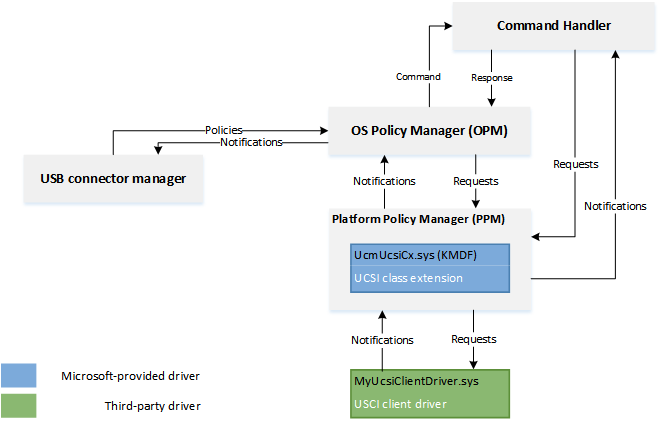
If your UCSI-compliant hardware uses a transport other than ACPI, you need to write a UCSI client driver.
Drivers for supporting USB Type-C components for systems with embedded controllers
Here's an example of a system with an embedded controller.
In the preceding example, USB role switching is handled in the firmware of the system and USB Role Switch driver stack isn't loaded. In another system, the driver stack may not get loaded because dual role isn't supported.
In the preceding image,
USB device-side drivers
The USB device-side drivers service the function/device/peripheral. The USB function controller class extension supports MTP (Media Transfer Protocol) and charging using BC 1.2 chargers. Microsoft provides in-box client drivers for Synopsys USB 3.0 and ChipIdea USB 2.0 controllers. You can write a custom client driver for your function controller by using USB function controller client driver programming interfaces. For more information, see Developing Windows drivers for USB function controllers.
The SoC vendor might provide you with the USB function lower filter driver for charger detection. You can implement your own filter driver if you're using the in-box Synopsys USB 3.0 or ChipIdea USB 2.0 client driver.
USB host-side drivers
The USB host-side drivers are a set of drivers that work with EHCI or XHCI compliant USB host controllers. The drivers are loaded if the role-switch driver enumerates the host role. If your host controller isn't specification-compliant, then you can write a custom driver by using USB host controller extension (UCX) programming interface. For information, see Developing Windows drivers for USB host controllers.
Not all USB devices classes are supported on Windows 10 Mobile.
USB connector manager
Microsoft provides a UCSI in-box driver with Windows (UcmUcsiCx.sys) that implements the features defined in the USB Type-C Connector System Software Interface Specification. The specification describes the capabilities of UCSI and explains the registers and data structures, for hardware component designers, system builders, and device driver developers.
This driver is intended for systems with embedded controllers. This driver is a client to the Microsoft-provided USB connector manager class extension driver (Ucmcx.sys). The driver handles tasks such as initiating a request to the firmware to change the data or power roles and getting information needed to provide troubleshooting messages to the user.
UCSI commands required by Windows
See the UCSI specification for commands that are required in all UCSI implementations.
In addition to the commands marked as Required, Windows requires these commands:
- GET_ALTERNATE_MODES
- GET_CAM_SUPPORTED
- GET_PDOS
- SET_NOTIFICATION_ENABLE: The system or controller must support the following notifications within SET_NOTIFICATION_ENABLE:
- Supported Provider Capabilities Change
- Negotiated Power Level Change
- GET_CONNECTOR_STATUS: The system or controller must support these connector status changes within GET_CONNECTOR_STATUS:
- Supported Provider Capabilities Change
- Negotiated Power Level Change
For information about the tasks required to implement UCSI in the BIOS, see Intel BIOS Implementation of UCSI.
UCM-UCSI ACPI device for UCSI 2.0 and greater
Starting in Windows 11, version 22H2 September Update, the Windows UCM-UCSI ACPI device drivers support UCSI specification version 2.0 and 2.1. The UCSI specification 2.0 has breaking changes in the memory mapping of its data structures as defined in UCSI specification Table 3-1 Data Structures. To maintain backward compatibility, Windows requires the UCSI PPM of specification version 2.0 or greater to implement the following _DSM function under the UCM-UCSI ACPI device in ACPI firmware and return a nonzero value to indicate that UCSI OPM should follow the reported UCSI specification version.
- Arg0: UUID = 6F8398C2-7CA4-11E4-AD36-631042B5008F
- Arg1: Revision ID = 0
- Arg2: Function index = 5
- Arg3: Empty package (not used)
Return value:
| Element | Object type | Description |
|---|---|---|
| UsePpmReportedUcsiVersion | Integer (32-bit) | 0x00000000 (Default): If the VERSION structure, as defined in UCSI specification Table 3-1 Data Structures, has the value 2.0 or greater, UCSI OPM still follows UCSI specification 1.2. Otherwise, UCSI OPM follows the UCSI specification as per the value in the VERSION structure. |
Note
For UCM-UCSI ACPI devices, this is a new function in an existing _DSM method. Other functions of this _DSM method should have been implemented per the Intel BIOS implementation of UCSI document. Function 0, which returns a bitmask of all the supported functions, should be updated accordingly, as well.
Example flow for UCSI
The examples given in this section describe interaction between the USB Type-C hardware/firmware, UCSI driver, and the operating system.
DRP role detection
- USB Type-C hardware/firmware detects a device-attach event and the Windows 10 system DRP system initially becomes the UFP role.
- The firmware sends a notification indicating a change in the connector.
- The UCSI driver sends a GET_CONNECTOR_STATUS request.
- The firmware responds that its Connect Status = 1 and Connector Partner Type = DFP.
- The drivers in the USB function stack respond to the enumeration.
- The USB connector manager class extension recognizes that the USB function stack has loaded and hence the system is in the wrong state. It tells the UCSI driver to send Set USB Operation Role and Set Power Direction Role requests to the firmware.
- USB Type-C hardware/firmware initiates the role-swap operation with the DFP.
Detecting a charger mismatch error condition
USB Type-C hardware/firmware detects that a charger is connected and negotiates a default power contract. It also observes that the charger isn't providing sufficient power to the system.
USB Type-C hardware/firmware sets the slow charging bit.
- The firmware sends a notification indicating a change in the connector.
- The UCSI driver sends a GET_CONNECTOR_STATUS request.
- The firmware responds with Connect Status = 1, Connector Partner Type=DFP, and Battery Charging Status = Slow/Trickle.
The USB connector manager class extension sends notification to the UI to display the charger mismatch troubleshoot message.
How to test UCSI
There are many ways to test your UCSI implementation. To test individual commands in your UCSI BIOS/EC implementation, use UCSIControl.exe, which is provided in the MUTT Software Pack. To test your complete UCSI implementation, use both the UCSI tests that can be found in the Windows Hardware Lab Kit (HLK) and the steps in the Type-C Manual Interop Procedures.
UCSIControl.exe
You can test individual commands in your UCSI BIOS/EC implementation by using UCSIControl.exe. This tool enables you to send UCSI commands to the firmware through the UCSI driver. It requires the driver to be loaded and running, and also have the test interface to the driver enabled. By default, this interface isn't enabled so as to prevent it from being accessible to unauthorized users on a retail system.
Locate the device node in Device Manager (devmgmt.msc) named UCSI USB Connector Manager. The node is under the Universal Serial Bus controllers category.
Select and hold (or right-click) on the device, and select Properties and open the Details tab.
Select Device Instance Path from the drop-down and note the property value.
Open Registry Editor (regedit.exe).
Navigate to the device instance path under this key.
HKEY_LOCAL_MACHINE\System\CurrentControlSet\Enum\<device-instance-path>\Device Parameters
Create a DWORD value named TestInterfaceEnabled and set the value to 0x1.
Restart the device by selecting the Disable option on the device node in Device Manager, and then selecting Enable. Alternatively, you can restart the PC.
You can view the help by running UcsiControl.exe /?.
Here are the common commands:
| UCSI command | UcsiControl.exe command |
|---|---|
| PPM Reset | UcsiControl.exe Send 0 1 |
| Connector Reset | Soft reset: UcsiControl.exe Send 0 10003 Hard reset: UcsiControl.exe Send 0 810003 |
| Set Notification Enable | All notifications: UcsiControl.exe Send 0 ffff0005 Only command completion: UcsiControl.exe Send 0 00010005 No notification: UcsiControl.exe Send 0 00000005 |
| Get Capability | UcsiControl.exe Send 0 6 |
| Get Connector Capability | UcsiControl.exe Send 0 10007 |
| Set UOM | DFP: UcsiControl.exe Send 0 810008 UFP: UcsiControl.exe Send 0 1010008 DRP: UcsiControl.exe Send 0 2010008 |
| Set UOR | DFP: UcsiControl.exe Send 0 810009 UFP: UcsiControl.exe Send 0 1010009 Accept: UcsiControl.exe Send 0 2010009 |
| Set PDR | Provider: UcsiControl.exe Send 0 81000B Consumer: UcsiControl.exe Send 0 101000B Accept: UcsiControl.exe Send 0 201000B |
| Get PDOs | Local Source: UcsiControl.exe Send 7 00010010 Local Sink: UcsiControl.exe Send 3 00010010 Remote Source: UcsiControl.exe Send 7 00810010 Remote Sink: UcsiControl.exe Send 3 00810010 |
| Get Connector Status | UcsiControl.exe Send 0 010012 |
| Get Error Status | UcsiControl.exe Send 0 13 |
Related topics
Feedback
Coming soon: Throughout 2024 we will be phasing out GitHub Issues as the feedback mechanism for content and replacing it with a new feedback system. For more information see: https://aka.ms/ContentUserFeedback.
Submit and view feedback for