Note
Access to this page requires authorization. You can try signing in or changing directories.
Access to this page requires authorization. You can try changing directories.
This tutorial describes how to install an Azure Stack Edge Pro 2 physical device. The installation procedure involves unpacking, rack mounting, and cabling the device.
The installation can take around two hours to complete.
In this tutorial, you learn how to:
- Unpack the device
- Rack mount the device
- Cable the device
Prerequisites
The prerequisites for installing a physical device as follows:
For the Azure Stack Edge resource
Before you begin, make sure that:
- You've completed all the steps in Prepare to deploy Azure Stack Edge Pro 2.
- You've created an Azure Stack Edge resource to deploy your device.
- You've generated the activation key to activate your device with the Azure Stack Edge resource.
For the Azure Stack Edge Pro 2 physical device
Before you deploy a device:
- Make sure that the device rests safely on a flat, stable, and level work surface.
- Verify that the site where you intend to set up has:
Standard AC power from an independent source.
-OR-
A power distribution unit (PDU) with an uninterruptible power supply (UPS).
An available 2U slot on the rack on which you intend to mount the device. If you wish to wall mount your device, you should have a space identified on the wall or a desk where you intend to mount the device.
For the network in the datacenter
Before you begin:
Review the networking requirements for deploying Azure Stack Edge Pro 2, and configure the datacenter network per the requirements. For more information, see Azure Stack Edge Pro 2 networking requirements.
Make sure that the minimum Internet bandwidth is 20 Mbps for optimal functioning of the device.
Unpack the device
This device is shipped in a single box. Complete the following steps to unpack your device.
- Place the box on a flat, level surface.
- Inspect the box and the packaging foam for crushes, cuts, water damage, or any other obvious damage. If the box or packaging is severely damaged, don't open it. Contact Microsoft Support to help you assess whether the device is in good working order.
- Unpack the box. After unpacking the box, make sure that you have:
One single enclosure Azure Stack Edge Pro 2 device.
One power cord.
One packaged bezel.
A pair of packaged Wi-Fi antennas in the accessory box.
Note
The accessory box includes Wi-Fi antennas, but Wi-Fi capability is not supported for the Azure Stack Edge device. The antennas should not be used.
One packaged mounting accessory which could be:
- A 4-post rack slide rail, or
- A 2-post rack slide, or
- A wall mount (may be packaged separately).
A safety, environmental, and regulatory information booklet.
If you didn't receive all of the items listed here, Contact Microsoft Support. The next step is to mount your device on a rack or wall.
Rack mount the device
The device can be mounted using one of the following mounting accessory:
- A 4-post rackmount.
- A 2-post rackmount.
- A wallmount.
If you have received 4-post rackmount, use the following procedure to rack mount your device. For other mounting accessories, see Racking using a 2-post rackmount or Mounting the device on the wall.
If you decide not to mount your device, you can also place it on a desk or a shelf.
Prerequisites
- Before you begin, make sure to read the Safety instructions for your device.
- Begin installing the rails in the allotted space that is closest to the bottom of the rack enclosure.
- For the rail mounting configuration:
- You need to use 10L M5 screws. Make sure that these are included in your rail kit.
- You need a Phillips head screwdriver.
Identify the rail kit contents
Locate the components for installing the rail kit assembly:
- Inner rails.
- Chassis of your device.
- 10L M5 screws.
Install rails
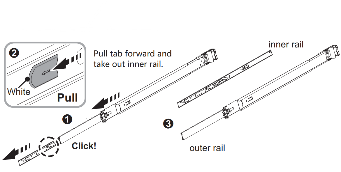
Remove the inner rail.
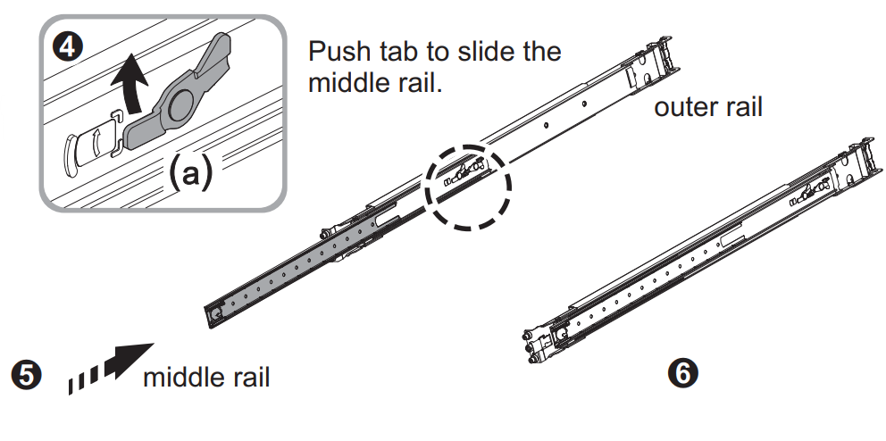
Push and slide the middle rail back.
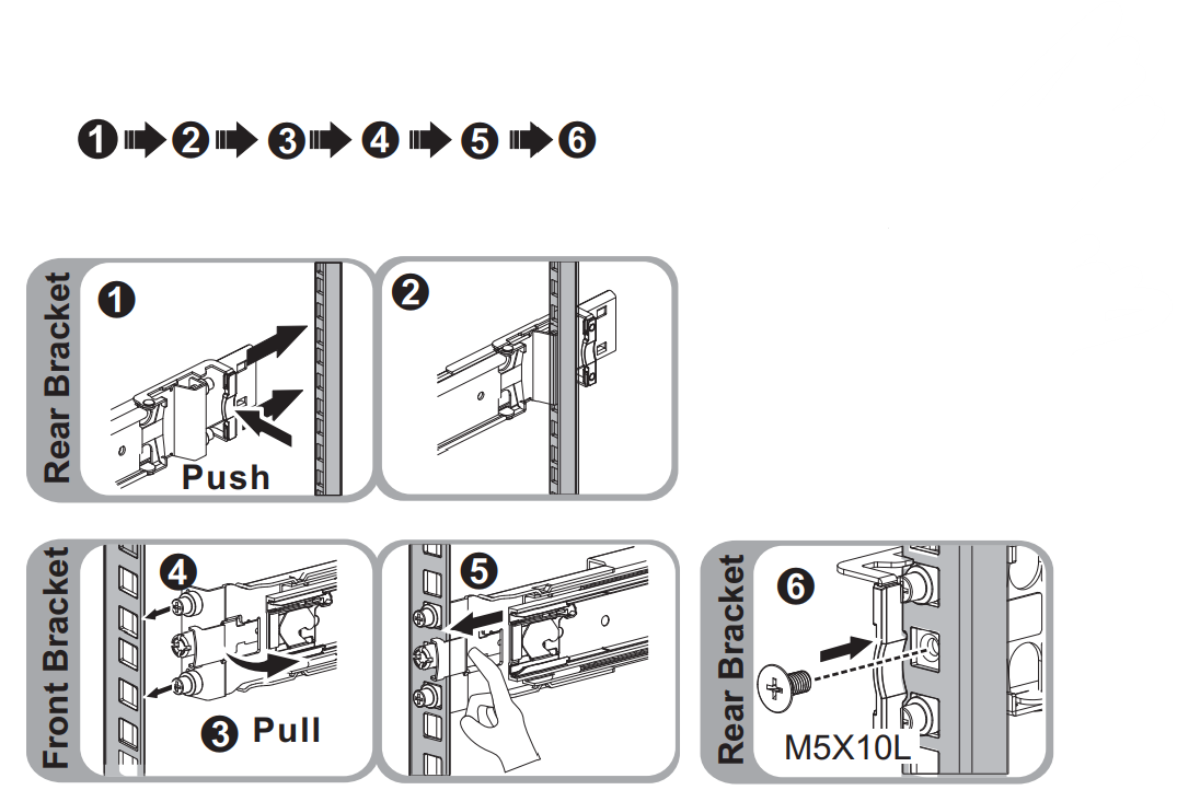
Install the inner rail onto the chassis. Make sure to fasten the inner rail screw.

Fix the outer rail and the bracket assembly to the frame. Ensure the latch is fully engaged with the rack post.

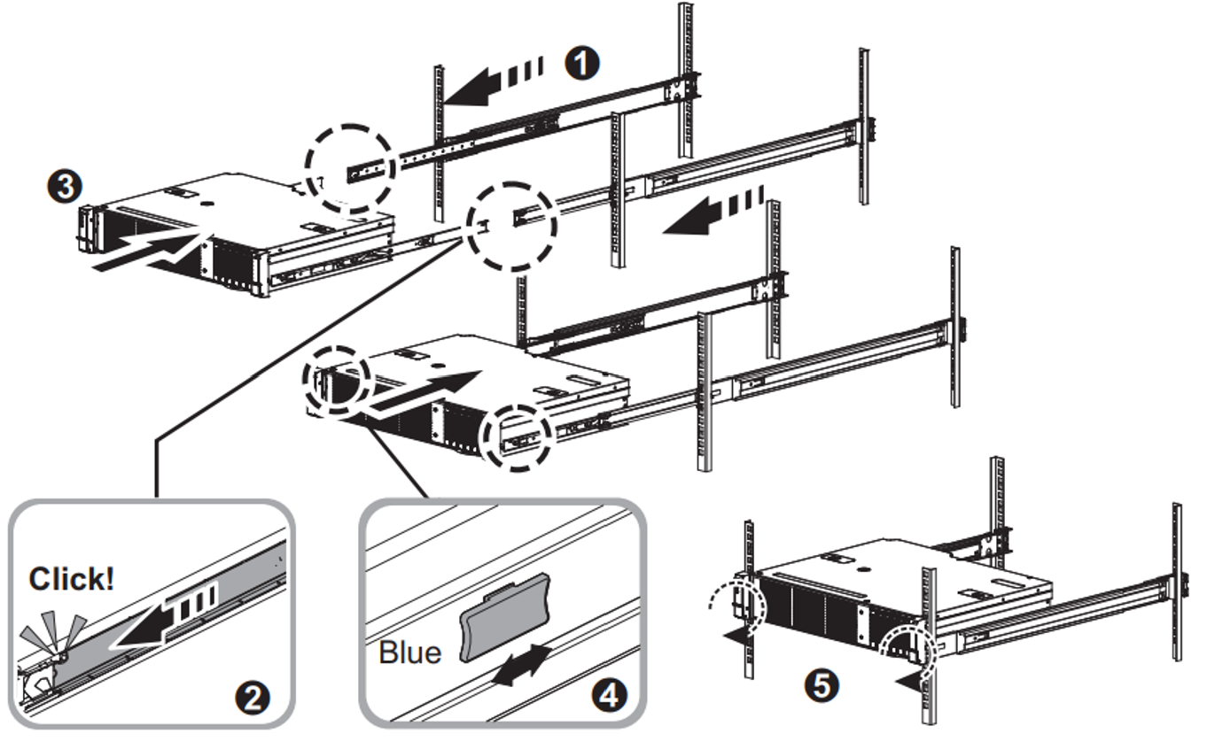
Insert the chassis to complete the installation.
- Pull the middle rail so that it is fully extended in lock position. Ensure the ball bearing retainer is located at the front of the middle rail (reference diagrams 1 and 2).
- Insert the chassis into the middle rail (reference diagram 3).
- Once you hit a stop, pull and push the blue release tab on the inner rails (reference diagram 4).
- Tighten the M5 screws of the chassis to the rail once the server is seated (reference diagram 5).
Install the bezel
After the device is mounted on a rack, install the bezel on the device. Bezel serves as the protective face plate for the device.
Locate two fixed pins on the right side of the bezel, and two spring-loaded pins on the left side of the bezel.
Insert the bezel in at an angle with fixed pins going into holes in right rack ear.
Push
[>shaped latch to the right, move left side of bezel into place, then release the latch until the spring pins engage with holes in left rack ear.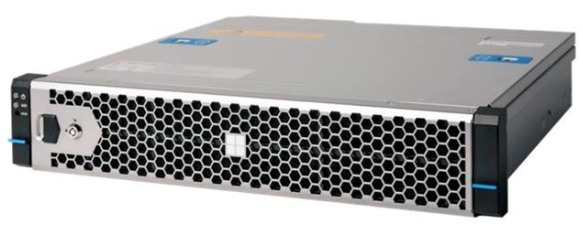
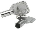
Lock the bezel in place using the provided security key.
Cable the device
The following procedures explain how to cable your Azure Stack Edge Pro 2 device for power and network.
Cabling checklist
Before you start cabling your device, you need the following things:
Your Azure Stack Edge Pro 2 physical device, unpacked, and rack mounted.
One power cable (included in the device package).
Use 10G-BASET RJ-45 network cables (CAT-5e or CAT-6) to connect to Port1 and Port2. They can operate at either 1Gb/s or 10Gb/s.
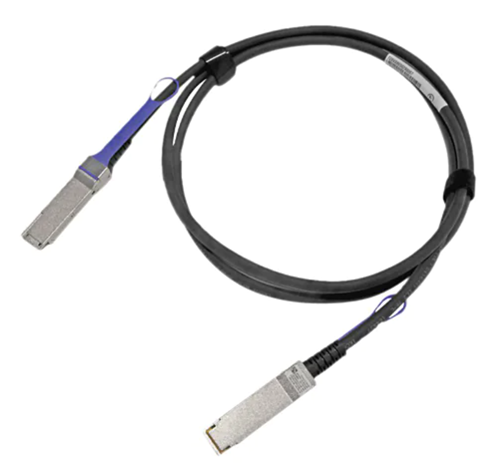
One 100-GbE QSFP28 passive direct attached cable (Microsoft validated) for each data network interface Port 3 and Port 4 to be configured. Here is an example of the QSFP28 DAC connector:
For a full list of supported cables, modules, and switches, see Firmware compatible products.
Access to one power distribution unit.
At least one 100-GbE network switch to connect a 10/1-GbE or a 100-GbE network interface to the internet for data. At least one data network interface from among Port 2, Port 3, and Port 4 needs to be connected to the Internet (with connectivity to Azure).
A pair of Wi-Fi antennas (included in the accessory box).
Note
The accessory box includes Wi-Fi antennas, but Wi-Fi capability is not supported for the Azure Stack Edge device. The antennas should not be used.
Note
The Azure Stack Edge Pro 2 device should be connected to the datacenter network so that it can ingest data from data source servers.
Device front panel
On your device:
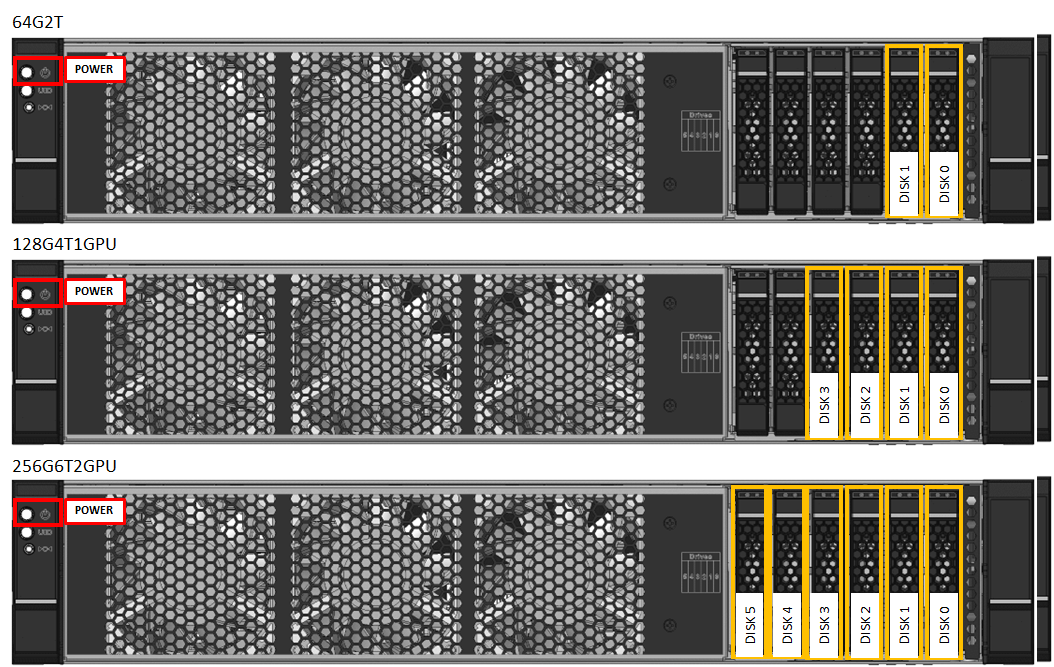
The front panel has disk drives and a power button. The front panel has:
- Has six disk slots in the front of your device.
- Has 2, 4, or 6 data disks in the 6 available slots depending on the specific hardware configuration.
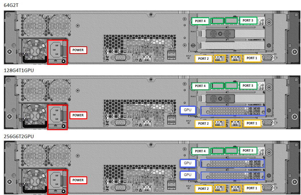
Device back plane
On your device:
The back plane has:
Four network interfaces:
- Two 10/1-Gbps interfaces, Port 1 and Port 2.
- Two 100-Gbps interfaces, Port 3 and Port 4.
One network card corresponding to two high-speed ports and two built-in 10/1-GbE ports:
- Intel Ethernet X722 network adapter - Port 1, Port 2.
- Mellanox dual port 100 GbE ConnectX-6 Dx network adapter - Port 3, Port 4.
Two Wi-Fi Sub miniature version A (SMA) connectors located on the faceplate of PCIe card slot located below Port 3 and Port 4. The Wi-Fi antennas are installed on these connectors.
Two, one, or no Graphical Processing Units (GPUs).
Power cabling
Follow these steps to cable your device for power:
- Identify the various ports on the back plane of your device.
- Locate the disk slots and the power button on the front of the device.
- Connect the power cord to the PSU in the enclosure.
- Attach the power cord to the power distribution unit (PDU).
- Press the power button to turn on the device.
Network cabling
Follow these steps to cable your device for network:
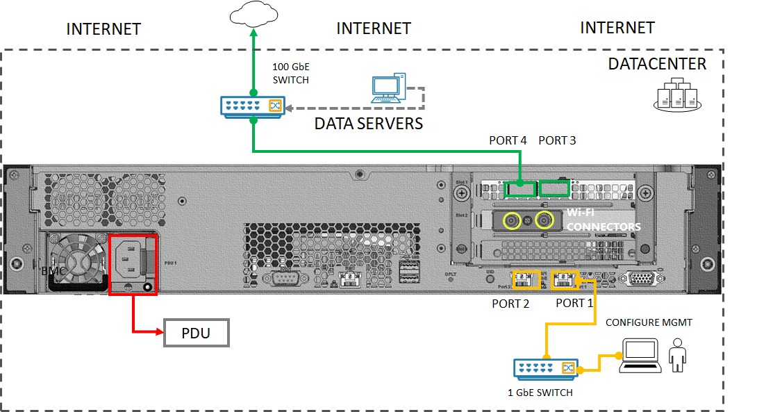
Connect the 10/1-GbE network interface Port 1 to the computer that's used to configure the physical device. Port 1 is used for the initial configuration of the device.
Note
If connecting the computer directly to your device (without going through a switch), use a crossover cable or a USB Ethernet adapter.
Connect one or more of Port 2, Port 3, Port 4 to the datacenter network/internet.
- If connecting Port 2, use the 1-GbE RJ-45 network cable.
- For the 100-GbE network interfaces, use the QSFP28 passive direct attached cable (tested in-house).
The back plane of a cabled device would be as follows:
Note
Using USB ports to connect any external device, including keyboards and monitors, is not supported for Azure Stack Edge devices.
Next steps
In this tutorial, you learned how to:
- Unpack the device
- Rack the device
- Cable the device
Advance to the next tutorial to learn how to connect to your device.