Note
Access to this page requires authorization. You can try signing in or changing directories.
Access to this page requires authorization. You can try changing directories.
Starting in Windows 10, an inbox USB Video Class (UVC) driver is provided for devices compliant with USB Video Class specification (versions 1.0 to 1.5). This driver supports color and sensor type cameras. This document outlines how to expose certain capabilities of a UVC compliant camera to the applications through the inbox driver.
Terminology
| Keyword | Description |
|---|---|
| UVC | USB Video Class |
| UVC driver | USBVideo.sys driver that ships with the OS |
| IR | Infrared |
| Color camera | The camera that outputs color streams (for example, RGB or YUV cameras) |
| Sensor camera | The camera that outputs non-color streams (for example, IR or Depth cameras) |
| BOS | Binary Device Object Store |
| MS OS 2.0 Descriptor | Microsoft platform specific BOS device capability descriptor |
Sensor cameras
Windows supports two categories of cameras. One is a color camera and the other one is a non-color sensor camera. RGB or YUV cameras are categorized as color cameras and non-color cameras like gray scale, IR and Depth cameras are categorized as sensor cameras. The UVC driver supports both types of cameras. We recommend the camera firmware specify a value based on which the UVC driver would register the camera under one or both supported categories.
A camera that supports color only format types should be registered under KSCATEGORY_VIDEO_CAMERA. A camera that supports IR or Depth-only format types should be registered under KSCATEGORY_SENSOR_CAMERA. A camera that supports both color and non-color format types should be registered under KSCATEGORY_VIDEO_CAMERA and KSCATEGORY_SENSOR_CAMERA. This categorization helps applications to select the camera that they want to work with.
A UVC camera can specify its category preference through attributes, SensorCameraMode and SkipCameraEnumeration, in its BOS MS OS 2.0 Descriptor detailed in following sections.
The attribute SensorCameraMode takes a value 1 or 2.
A value of 1 will register the device under KSCATEGORY_SENSOR_CAMERA. In addition to this, specify a value of 1 for SkipCameraEnumeration to make the camera available to applications looking only for sensor cameras. A camera that exposes only sensor camera media types should use this value.
A value of 2 for SensorCameraMode will register the device under KSCATEGORY_SENSOR_CAMERA & KSCATEGORY_VIDEO_CAMERA. This makes the camera available for applications looking for either sensor and color cameras. A camera that exposes both sensor camera and color camera media types should use this value.
We recommend you specify the above-mentioned registry value using the BOS descriptor. Refer to the Example composite device section below for a sample BOS descriptor with a platform specific MS OS 2.0 descriptor.
If you can't update the device firmware as described above, you can use a custom INF and specify that your camera need to be registered as a sensor camera by specifying a value for SensorCameraMode and SkipCameraEnumeration as follows:
A custom INF file (based on the inbox UVC driver) must include the following AddReg entries:
SensorCameraMode: REG_DWORD: 1 (to register as a sensor camera)
SkipCameraEnumeration: REG_DWORD: 1 (make it available only for IR applications)
An example of the custom INF section is as follows:
[USBVideo.NT.HW]
AddReg=USBVideo.HW.AddReg

[USBVideo.HW.AddReg]
HKR,, SensorCameraMode, 0x00010001,1      ; places the value under device HW
                                          ; Registry key

HKR,, SkipCameraEnumeration, 0x00010001,1 ; This makes the camera available
                                          ; only for application looking for
                                          ; IR cameras
If the SensorCameraMode and SkipCameraEnumeration attributes aren't specified in the firmware or the INF, the camera is registered as a color camera and will be visible only to color camera aware applications.
IR stream
The Windows inbox USB video class (UVC) driver supports cameras that capture the scene in YUV format and transmit the pixel data over USB as uncompressed YUV or as compressed MJPEG frames.
The following format type GUIDs should be specified in the stream video format descriptor, as defined in the WDK ksmedia.h header file:
| Type | Description |
|---|---|
| KSDATAFORMAT_SUBTYPE_L8_IR | Uncompressed 8-bit luma plane. This type maps to MFVideoFormat_L8. |
| KSDATAFORMAT_SUBTYPE_L16_IR | Uncompressed 16-bit luma plane. This type maps to MFVideoFormat_L16. |
| KSDATAFORMAT_SUBTYPE_MJPG_IR | Compressed MJPEG frames. Media Foundation converts this into NV12 uncompressed frames and uses only the luma plane. |
When these format type GUIDs are specified in the guidFormat field of the frame descriptor, the Media Foundation capture pipeline marks the stream as IR stream. Applications written with Media Foundation FrameReader API will be able to consume the IR stream. No scaling or conversions of the IR frames are supported by the pipeline for IR streams.
A stream exposing IR format types must not expose RGB or Depth format types.
// Example Format Descriptor for UVC 1.1 frame based format

typedef struct _VIDEO_FORMAT_FRAME
{
    UCHAR bLength;
    UCHAR bDescriptorType;
    UCHAR bDescriptorSubtype;
    UCHAR bFormatIndex;
    UCHAR bNumFrameDescriptors;
    GUID  guidFormat;  // this field should contain the IR subtype GUID
    UCHAR bBitsPerPixel;
    UCHAR bDefaultFrameIndex;
    UCHAR bAspectRatioX;
    UCHAR bAspectRatioY;
    UCHAR bmInterlaceFlags;
    UCHAR bCopyProtect;
    UCHAR bVariableSize;
} VIDEO_FORMAT_FRAME, *PVIDEO_FORMAT_FRAME;
Note
IR streams will show up as regular capture streams in DShow.
Depth stream
Windows inbox USB Video Class driver supports cameras that produce Depth streams. These cameras capture the depth information (For example, time of flight) of the scene and transmit the depth map as uncompressed YUV frames over USB. The following format type GUID should be specified in the stream video format descriptor, as defined in the WDK ksmedia.h header file:
| Type | Description |
|---|---|
| KSDATAFORMAT_SUBTYPE_D16 | 16-bit depth map values. This type is identical to MFVideoFormat_D16. The values are in millimeters. |
When the format type GUID is specified in the guidFormat member of the frame descriptor, the Media Foundation capture pipeline marks the stream as depth stream. Applications written with FrameReader API will be able to consume the depth stream. No scaling or conversions of the depth frames are supported by the pipeline for depth streams.
A stream exposing Depth format types must not expose RGB or IR format types.
// Example Format Descriptor for UVC 1.1 frame based format
typedef struct _VIDEO_FORMAT_FRAME
{
    UCHAR bLength;
    UCHAR bDescriptorType;
    UCHAR bDescriptorSubtype;
    UCHAR bFormatIndex;
    UCHAR bNumFrameDescriptors;
    GUID guidFormat; // this field should contain the IR subtype GUID
    UCHAR bBitsPerPixel;
    UCHAR bDefaultFrameIndex;
    UCHAR bAspectRatioX;
    UCHAR bAspectRatioY;
    UCHAR bmInterlaceFlags;
    UCHAR bCopyProtect;
    UCHAR bVariableSize;
} VIDEO_FORMAT_FRAME, *PVIDEO_FORMAT_FRAME;
Note
Depth streams show up as regular capture streams in DShow.
Grouping cameras
Windows supports grouping of cameras based on their container ID to aid applications work with related cameras. For example, an IR camera and a Color camera present on the same physical device can be exposed to the OS as related cameras. This makes applications like Windows Hello use the related cameras for their scenarios.
The relation between the camera functions could be specified in the camera's BOS descriptor in firmware. The UVC driver will make use of this information and expose these camera functions as related. This makes the OS camera stack expose them as a related group of cameras to the applications.
The camera firmware must specify a UVC-FSSensorGroupID, which is a GUID in string form with the curly parenthesis. The cameras that have the same UVC-FSSensorGroupID will be grouped together.
The sensor group can be given a name by specifying UVC-FSSensorGroupName, a Unicode string, in the firmware.
Refer to the Example composite device section below for an illustrative example BOS that specifies UVC-FSSensorGroupID and UVC-FSSensorGroupName.
If you can't update the device firmware as described above, you can use a custom INF and specify that your camera is part of a sensor group by specifying a sensor group ID and name as follows. The custom INF file (based on the inbox UVC driver) must include the following AddReg entries:
FSSensorGroupID: REG_SZ: "{your sensor group ID GUID}"
FSSensorGroupName: REG_SZ: "your sensor group friendly name"
An example for the custom INF section would be as follows:
[USBVideo.NT.Interfaces]
AddInterface=%KSCATEGORY_CAPTURE%,GLOBAL,USBVideo.Interface
AddInterface=%KSCATEGORY_RENDER%,GLOBAL,USBVideo.Interface
AddInterface=%KSCATEGORY_VIDEO%,GLOBAL,USBVideo.Interface
AddInterface=%KSCATEGORY_RENDER_EXT%,GLOBAL,USBVideo.Interface
AddInterface=%KSCATEGORY_VIDEO_CAMERA%,GLOBAL,USBVideo.Interface

[USBVideo.Interface]
AddReg=USBVideo.Interface.AddReg

[USBVideo.Interface.AddReg]
HKR,,CLSID,,%ProxyVCap.CLSID%
HKR,,FriendlyName,,%USBVideo.DeviceDesc%
HKR,,RTCFlags,0x00010001,0x00000010
HKR,, FSSensorGroupID,0x00000000,%FSSensorGroupID%
HKR,, FSSensorGroupName,0x00000000,%FSSensorGroupName%
Note
Sensor Groups are not supported in DShow capture pipeline.
Method 2 or Method 3 still capture support
UVC specification does provide a mechanism to specify if the video streaming interface supports Method 1/2/3 type still image capture. To make the OS take advantage of the device's Method 2/3 still image capture support, through UVC driver, the device firmware could specify a value in the BOS descriptor.
The value to specify to enable Method 2/3 still image capture is a DWORD named UVC-EnableDependentStillPinCapture. Specify its value using the BOS descriptor. The Example composite device below illustrates enabling still image capture with an example BOS descriptor.
If you can't update the device firmware as described above, you can use a custom INF to specify that your camera supports Method 2 or Method 3 still capture method.
The custom INF file (based on either custom UVC driver or inbox UVC driver) must include the following AddReg entry:
EnableDependentStillPinCapture: REG_DWORD: 0x0 (Disabled) to 0x1 (Enabled)
When this entry is set to Enabled (0x1), the capture pipeline leverages Method 2/3 for still image capture (assuming the firmware also advertises support for Method 2/3 as specified by UVC spec).
An example for the custom INF section is as follows:
[USBVideo.NT.Interfaces]
AddInterface=%KSCATEGORY_CAPTURE%,GLOBAL,USBVideo.Interface
AddInterface=%KSCATEGORY_RENDER%,GLOBAL,USBVideo.Interface
AddInterface=%KSCATEGORY_VIDEO%,GLOBAL,USBVideo.Interface
AddInterface=%KSCATEGORY_RENDER_EXT%,GLOBAL,USBVideo.Interface
AddInterface=%KSCATEGORY_VIDEO_CAMERA%,GLOBAL,USBVideo.Interface

[USBVideo.Interface]
AddReg=USBVideo.Interface.AddReg

[USBVideo.Interface.AddReg]
HKR,,CLSID,,%ProxyVCap.CLSID%
HKR,,FriendlyName,,%USBVideo.DeviceDesc%
HKR,,RTCFlags,0x00010001,0x00000010
HKR,,EnableDependentStillPinCapture,0x00010001,0x00000001
Device MFT Chaining
Device MFT is the recommended user mode plugin mechanism for IHVs and OEMs to extend the camera functionality on Windows.
Prior to Windows 10, version 1703, the camera pipeline supported only one DMFT extension plugin.
Starting with Windows 10, version 1703, the Windows camera pipeline supports an optional chain of DMFTs with maximum of two DMFTs.
Starting in Windows 11, version 22H2, the Windows camera pipeline supports an optional chain of DMFTs with maximum of four DMFTs.
This provides greater flexibility for OEMs and IHVs to provide value-add in the form of post processing camera streams. For example, a device could use PDMFT along with an IHV DMFT and an OEM DMFT.
The following figure illustrates the architecture involving a chain of DMFTs.
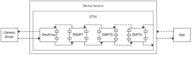
Capture samples flow from camera driver to DevProxy, then go through the DMFT chains. Every DMFT in the chain has a chance to process the sample. If the DMFT doesn't want to process the sample, it can act as a pass-through just pass the sample to next DMFT.
For controls like KsProperty, the call goes upstream – the last DMFT in the chain gets the call first, the call can be handled there or get passed to previous DMFT in the chain.
Errors are propagated from DMFT to DTM then to applications. For IHV/OEM DMFTs, if any of the DMFT fails to instantiate, it will be a fatal error for DTM.
Requirements on DMFTs:
The input pin count of the DMFT must match with the output pin count of previous DMFT, otherwise DTM would fail during initialization. However, the input and output pin counts of the same DMFT don't need to match.
DMFT needs to support interfaces - IMFDeviceTransform, IMFShutdown, IMFRealTimeClientEx, IKsControl and IMFMediaEventGenerator; IMFTransform may need to be supported if there's MFT0 configured or the next DMFT in the chain requires IMFTransform support.
On 64-bit systems that don't make use of Frame Server, both 32-bit and 64-bit DMFTs must be registered. Given that a USB camera might get plugged into an arbitrary system, for "external" (or non-inbox) USB cameras, the USB camera vendor should supply both 32-bit and 64-bit DMFTs.
Configuring the DMFT chain
A camera device can optionally supply a DMFT COM object in a DLL using a custom INF file that uses sections of the inbox USBVideo.INF.
In the custom .INF file's "Interface AddReg" section, specify the DMFT CLSIDs by adding following registry entry:
CameraDeviceMftCLSIDChain (REG_MULTI_SZ) %Dmft0.CLSID%,%Dmft.CLSID%,%Dmft2.CLSID%
As shown in the sample INF settings below (replace the %Dmft0.CLSID% and % Dmft1.CLSID% with the actual CLSID strings you're using for your DMFTs), there are maximum of 2 CLSIDs allowed in Windows 10, version 1703, and the first one is closest to DevProxy and the last one is the last DMFT in the chain.
Platform DMFT CLSID is {3D096DDE-8971-4AD5-98F9-C74F56492630}.
Some example CameraDeviceMftCLSIDChain settings:
No IHV/OEM DMFT or Platform DMFT
- CameraDeviceMftCLSIDChain = "" (or no need to specify this registry entry)
IHV/OEM DMFT
- CameraDeviceMftCLSIDChain = %Dmft.CLSID%
Platform DMFT <-> IHV/OEM DMFT
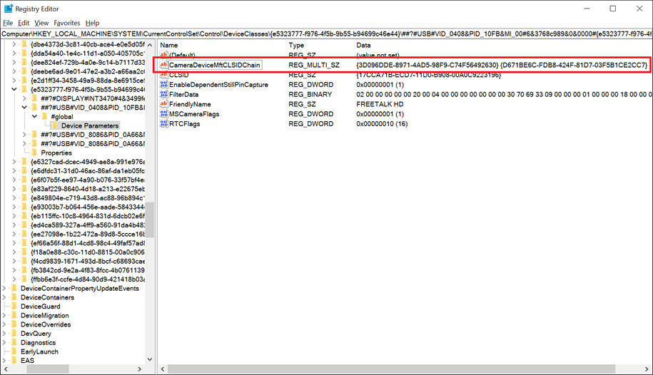
CameraDeviceMftCLSIDChain = "{3D096DDE-8971-4AD5-98F9-C74F56492630}",%Dmft.CLSID%
Here's a screenshot of the result registry key for a USB camera with the Platform DMFT and a DMFT (with GUID {D671BE6C-FDB8-424F-81D7-03F5B1CE2CC7}) in the chain.
IHV/OEM DMFT0 <-> IHV/OEM DMFT1
- CameraDeviceMftCLSIDChain = %Dmft0.CLSID%,%Dmft1.CLSID%,
Note
The CameraDeviceMftCLSIDChain can have a maximum 2 of CLSIDs.
If CameraDeviceMftCLSIDChain is configured, the legacy CameraDeviceMftCLSID settings are skipped by DTM.
If CameraDeviceMftCLSIDChain isn't configured and the legacy CameraDeviceMftCLSID is configured, then the chain would look like (if its USB camera and supported by Platform DMFT and Platform DMFT is enabled) DevProxy <–> Platform DMFT <–> OEM/IHV DMFT or (if the camera isn't supported by Platform DMFT or Platform DMFT is disabled) DevProxy <-> OEM/IHV DMFT.
Example INF file settings:
[USBVideo.Interface.AddReg]
HKR,,CLSID,,%ProxyVCap.CLSID%
HKR,,FriendlyName,,%USBVideo.DeviceDesc%
HKR,,RTCFlags,0x00010001,0x00000010
HKR,,EnablePlatformDmft,0x00010001,0x00000001
HKR,,DisablePlatformDmftFeatures,0x00010001,0x00000001
HKR,,CameraDeviceMftCLSIDChain, 0x00010000,%Dmft0.CLSID%,%Dmft1.CLSID%
Platform Device MFT
Starting in Windows 10, version 1703, Windows provides an inbox Device MFT for UVC cameras known as Platform DMFT (PDMFT) on an opt-in basis. This DMFT allows IHVs and OEMs to take advantage of Windows provided post processing algorithms.
| Features supported by Platform DMFT | Windows Release |
|---|---|
| Enables face-based Region of Interest (ROI) for 3A adjustments in ROI-capable USB cameras. | Windows 10, version 1703 |
Note
If the camera does not support UVC 1.5 based ROI, then the PDMFT will not load even if the device opted in to use PDMFT.
A UVC camera could opt in to use platform DMFT by specifying the EnablePlatformDmft through BOS descriptor.
The value to specify to enable Platform DMFT is a DWORD by name UVC-EnablePlatformDmft and specify its value using the BOS descriptor. The Example composite device section below illustrates enabling Platform DMFT with an example BOS descriptor.
If you can't update the device firmware as described above, you can use a custom INF file to enable Platform DMFT for the device.
The custom INF file (based on either custom UVC driver or inbox UVC driver) must include the following AddReg entry:
EnablePlatformDmft: REG_DWORD: 0x0 (Disabled) to 0x1 (Enabled)
When this entry is set to Enabled (0x1), the capture pipeline uses the inbox Platform DMFT for the device. The following shows an example of this custom INF section:
[USBVideo.NT.Interfaces]
AddInterface=%KSCATEGORY_CAPTURE%,GLOBAL,USBVideo.Interface
AddInterface=%KSCATEGORY_RENDER%,GLOBAL,USBVideo.Interface
AddInterface=%KSCATEGORY_VIDEO%,GLOBAL,USBVideo.Interface
AddInterface=%KSCATEGORY_RENDER_EXT%,GLOBAL,USBVideo.Interface
AddInterface=%KSCATEGORY_VIDEO_CAMERA%,GLOBAL,USBVideo.Interface

[USBVideo.Interface]
AddReg=USBVideo.Interface.AddReg

[USBVideo.Interface.AddReg]
HKR,,CLSID,,%ProxyVCap.CLSID%
HKR,,FriendlyName,,%USBVideo.DeviceDesc%
HKR,,RTCFlags,0x00010001,0x00000010
HKR,,EnablePlatformDmft,0x00010001,0x00000001
In Windows 10, version 1703, if a device opts in to use PDMFT then all features that are supported by the PDMFT are enabled (based on the device capabilities). Granular configuration of PDMFT features isn't supported.
Note
Face-based ROI coordinates are calculated relative to the field of view of the image transmitted into the PDMFT. If the field of view has been modified due to use of a control such as Zoom, Pan or Tilt or Digital Window, the camera is responsible for mapping the provided coordinates back to the sensor's full field of view, considering the current zoom/pan window.
Face Auth Profile via MS OS Descriptors
Windows 10 RS5 now enforces a Face Auth Profile V2 requirement for any camera with Windows Hello support. For MIPI based systems with custom camera driver stack, this support can be published either via an INF (or an Extension INF) or through a user mode plug-in (Device MFT).
However, for USB Video devices, a constraint with UVC based cameras is that for Windows 10 19H1, custom camera drivers aren't allowed. All UVC based cameras must use the inbox USB Video Class driver and any vendor extensions must be implemented in the form of a Device MFT.
For many OEM/ODMs, the preferred approach for camera modules is to implement much of the functionality within the module's firmware, that is, via Microsoft OS Descriptors.
The following cameras are supported for publish Face Auth Profile via the MSOS Descriptors (also called BOS descriptors):
RGB only camera to be used in Sensor Group with a separate IR camera.
IR only camera to be used in a Sensor Group with a separate RGB camera.
RGB+IR camera with separate IR and RGB pins.
Note
If the camera firmware cannot meet one of the three requirements detailed above, the ODM/OEM must use an Extension INF to declare Camera Profile V2.
Example Microsoft OS Descriptor Layout
Examples are included below for the following specifications:
Microsoft OS extended descriptors specification 1.0
Microsoft OS 2.0 descriptors specification
Microsoft OS Extended Descriptor 1.0 Specification
The extended properties OS descriptor has two components
- A fixed-length header section
- One or more variable length custom properties sections, which follow the header section
Microsoft OS 1.0 Descriptor Header Section
The Header Section describes a single custom property (Face Auth Profile).
| Offset | Field | Size (bytes) | Value | Description |
|---|---|---|---|---|
| 0 | dwLength | 4 | <> | |
| 4 | bcdVersion | 2 | 0x0100 | Version 1.0 |
| 6 | wIndex | 2 | 0x0005 | Extended property OS descriptor |
| 8 | wCount | 2 | 0x0001 | One custom property |
Microsoft OS 1.0 Descriptor Custom Property Section
| Offset | Field | Size (bytes) | Value | Description |
|---|---|---|---|---|
| 0 | dwSize | 4 | 0x00000036 (54) | Total size (in bytes) for this property. |
| 4 | dwPropertyDataType | 4 | 0x00000004 | REG_DWORD_LITTLE_ENDIAN |
| 8 | wPropertyNameLength | 2 | 0x00000024 (36) | Size (in bytes) of the property name. |
| 10 | bPropertyName | 36 | UVC-CPV2FaceAuth | "UVC-CPV2FaceAuth" string in Unicode. |
| 46 | dwPropertyDataLength | 4 | 0x00000004 | 4 bytes for property data (sizeof(DWORD)). |
| 50 | bPropertyData | 4 | See Data Schema Below | See Data Schema Below. |
Payload Schema
The UVC-CPV2FaceAuth data payload is a 32-bit unsigned integer. The high order 16-bit represents the 0 based index of the media type list exposed by the RGB pin. The low order 16-bit represents the 0 based index of the media type list exposed by the IR pin.
For example, a Type 3 Camera that exposes the following media types, in the order declared from the RGB pin:
YUY2, 640x480@30fps
MJPG, 1280x720@30fps
MJPG, 800x600@30fps
MJPG, 1920x1080@30fps
And the following media type for IR:
L8, 480x480@30fps
L8, 480x480@15fps
L8, 480x480@10fps
A payload value of 0x00010000 will result in the following Face Auth Profile being published:
Pin0:(RES==1280,720;FRT==30,1;SUT==MJPG) // Second media type (0x0001)
Pin1:(RES==480,480;FRT==30,1;SUT==L8) // First media type (0x0000)
Note
At the time of this writing, Windows Hello has a minimum requirement of 480x480@7.5fps for the RGB stream and 340x340@15fps for the IR stream. IHV/OEMs are required to select media types that satisfy this requirement when enabling Face Auth Profile.
Type 1 Camera Sample
For a Type 1 Camera, since there's no IR pin (with the expectation that a Type 1 Camera will be paired to a Type 2 Camera on the machine in a Sensor Group), only the RGB media type index is published. For the IR media type index, the low order 16-bit value of the payload must be set to 0xFFFF.
For example, if a Type 1 Camera exposed the following list of media types:
YUY2, 640x480@30fps
MJPG, 1280x720@30fps
MJPG, 800x600@30fps
MJPG, 1920x1080@30fps
To publish the CPV2FaceAuth using the MJPG, 1280x720@30fps media type, the payload must be set to 0x0001FFFF.
Type 2 Camera Sample
For a Type 2 Camera, the high order 16-bit must be set to 0xFFFF, with the low order 16-bit indicating the IR media type to be used.
For example, for a Type 2 Camera with the following media types:
L8, 480x480@30fps
L8, 480x480@15fps
L8, 480x480@10fps
If the first media type is used for Face Auth, the value must be: 0xFFFF0000.
Microsoft OS Extended Descriptor 2.0 Specification
MSOS Extended Descriptor 2.0 can be used to define the registry values to add Face Auth Profile support. This is done using the Microsoft OS 2.0 Registry Property Descriptor.
For the UVC-CPV2FaceAuth registry entry, the following shows a sample MSOS 2.0 descriptor set:
UCHAR Example2_MSOS20DescriptorSet_UVCFaceAuthForFutureWindows[0x3C] =
{
    //
    // Microsoft OS 2.0 Descriptor Set Header
    //
    0x0A, 0x00,               // wLength - 10 bytes
    0x00, 0x00,               // MSOS20_SET_HEADER_DESCRIPTOR
    0x00, 0x00, 0x0?, 0x06,   // dwWindowsVersion – 0x060?0000 for future Windows version
    0x3C, 0x00,               // wTotalLength – 60 bytes

    //
    // Microsoft OS 2.0 Registry Value Feature Descriptor
    //
    0x32, 0x00,               // wLength - 50 bytes
    0x04, 0x00,               // wDescriptorType – 4 for Registry Property
    0x04, 0x00,               // wPropertyDataType - 4 for REG_DWORD_LITTLE_ENDIAN
    0x30, 0x00,               // wPropertyNameLength – 36 bytes
    0x55, 0x00, 0x56, 0x00,   // Property Name - "UVC-CPV2FaceAuth"
    0x43, 0x00, 0x2D, 0x00,
    0x43, 0x00, 0x50, 0x00,
    0x56, 0x00, 0x32, 0x00,
    0x46, 0x00, 0x61, 0x00,
    0x63, 0x00, 0x65, 0x00,
    0x41, 0x00, 0x75, 0x00,
    0x74, 0x00, 0x68, 0x00,
    0x00, 0x00, 0x00, 0x00,
    0x04, 0x00,               // wPropertyDataLength – 4 bytes
    0x00, 0x00, 0x01, 0x00    // PropertyData – 0x00010000 (see Payload Schema)
}
When UVC-CPV2FaceAuth registry entry is added, devices don't need to publish the EnableDshowRedirection registry entry as described in DShow Bridge implementation guidance for UVC devices.
However, if the device vendor must support older versions of Windows and/or need to enable MJPEG decompression within Frame Server, the EnableDshowRedirection registry entry must be added.
Sensor Group Generation
When OEMs build systems using Type 1 and Type 2 Cameras to provide both RGB and IR streams for Windows Hello support, OEMs must declare the two cameras to be part of a synthesized Sensor Group.
This is done by declaring a FSSensorGroupId and FSSensorGroupName tag in an Extension INF to be created under the device interface property for each camera.
However, if Extension INF isn't provided, ODMs may use the same MSOS Descriptors to publish the FSSensorGroupId and FSSensorGroupName values. The inbox Windows 10 USB Video Class driver will automatically take any MSOS Descriptor whose Payload Name has been prefixed with "UVC-" and migrate the tag into the device interface property store (removing the "UVC-" prefix).
So a Type 1 and Type 2 Camera that publishes the following will allow the OS to synthesize the cameras into a multi-device Sensor Group for use with Windows Hello:
UVC-FSSensorGroupId
UVC-FSSensorGroupName
The payload for each tag must be a Unicode String. The UVC-FSSensorGroupId payload must be a GUID string in the following format:
{XXXXXXXX-XXXX-XXXX-XXXX-XXXXXXXXXXXX}
The value of the GUID must be the same between the Type 1 and Type 2 Cameras and both cameras must be added to the same physical chassis. For built in cameras, the physical chassis is the computer itself. For external cameras, both Type 1 and Type 2 Camera modules must be built into the same physical device connected to the computer.
Custom Device Interface Categories for Sensor Groups
Starting in 19H1, Windows is providing an IHV/OEM specified extension mechanism to allow publishing synthesized Sensor Groups into any custom or predefined category. Generation of a Sensor Group is defined by IHV/OEMs providing a Sensor Group ID key in the custom INF:
FSSensorGroupId: {Custom GUID}
FSSensorGroupName: <Friendly Name used for Sensor Group>
In addition to the two above AddReg entries in the INF, a new AddReg entry is defined for custom categories:
FSSensorGroupCategoryList: {GUID};{GUID};…;{GUID}
Multiple categories are defined using a semi-colon (;) delimited GUID list.
Each device declaring a matching FSSensorGroupId must declare the same FSSensorGroupCategoryList. If the list doesn't match, all lists are ignored and the Sensor Group are published by default into KSCATEGORY_SENSOR_GROUP as if no custom categories were defined.
Camera Rotation
UVC Control Cache
BOS and MS OS 2.0 descriptor
UVC compliant camera can specify Windows specific device configuration values in a platform capability BOS descriptor in its firmware using Microsoft OS 2.0 Descriptors. Refer the documentation on MS OS 2.0 descriptor to understand how to specify a valid BOS descriptor that conveys the device configuration to the OS.
Microsoft OS 2.0 Descriptor Set Header
| Offset | Field | Size (bytes) | Description |
|---|---|---|---|
| 0 | wLength | 2 | Length in bytes of this header, must be 10. |
| 2 | wDescriptorType | 2 | MSOS20_SET_HEADER_DESCRIPTOR |
| 4 | dwWindowsVersion | 4 | Windows version. |
| 8 | wTotalLength | 2 | The size of the entire MS OS 2.0 descriptor set including this header size. |
Microsoft OS 2.0 Registry Property Descriptor
| Offset | Field | Size (bytes) | Description |
|---|---|---|---|
| 0 | wLength | 2 | Length in bytes of this descriptor |
| 2 | wDescriptorType | 2 | MS_OS_20_FEATURE_REG_PROPERTY |
| 4 | wPropertyDataType | 2 | 0x04 (REG_DWORD_LITTLE_ENDIAN) |
| 6 | wPropertyNameLength | 2 | The length of the property name. |
| 8 | PropertyName | Variable | The name of the registry property. |
| 8+M | wPropertyDataLength | 2 | The length of the property data. |
| 10+M | PropertyData | Variable | Property Data |
When a valid MS OS 2.0 descriptor is specified in the firmware, the USB stack copies the configuration values into the device HW registry key show below:
HKEY_LOCAL_MACHINE\SYSTEM\CurrentControlSet\Enum\USB\<Device ID>\<Instance ID>\Device Parameters
UVC driver reads the configuration values from the device HW registry key and configures the device on the OS accordingly. For example, if the firmware specifies the device to be registered as a sensor camera using a configuration value, UVC driver registers the device just under that category.
Configuring UVC devices through platform BOS descriptor is a mechanism that was enabled in Windows 10, version 1703 to help UVC device vendors to configure the device without the need of an INF file on Windows OS.
Configuring UVC devices through custom INF is still supported and that takes precedence over BOS descriptor based mechanism. While specifying device properties through INF, you don't need to add the prefix "UVC-". This prefix is only needed for device properties that are specified through BOS descriptor and that are per interface instance specific. If your device needs user mode plugins like DMFT, then you need to supply an INF for installing the DMFT. It can't be configured using firmware.
Currently supported configuration values through BOS descriptor
| Configuration name | Type | Description |
|---|---|---|
| SensorCameraMode | REG_DWORD | Register the camera under a specific category. |
| UVC-FSSensorGroupID, UVC-FSSensorGroupName | REG_SZ | Group cameras with the same UVC-FSSensorGroupID |
| UVC-EnableDependentStillPinCapture | REG_DWORD | To enable still capture Method 2/3 |
| UVC-EnablePlatformDmft | REG_DWORD | To enable Platform DMFT |
When UVC driver sees the registry values with prefix "UVC-", it populates the device's category interface instance registry key, with the same values without the prefix. The driver does this for any variable specified by the firmware, not just the ones listed above.
HKEY_LOCAL_MACHINE\SYSTEM\CurrentControlSet\Control\DeviceClasses\{e5323777-f976-4f5b-9b55-b94699c46e44}\<Device Symbolic Link>\Device Parameters
For the OS to make use of the BOS Platform Device Capability and MS OS 2.0 descriptors, the device descriptor must specify the bcdUSB version to be 0x0210 or greater.
Example composite device
This section provides a BOS descriptor and a MS OS 2.0 descriptor for an example composite device with two camera functions. One function is a UVC color camera and the second function is a UVC IR camera.
The sample descriptors are as follows:
Register the color camera function under KSCATEGORY_VIDEO_CAMERA
Register the IR camera function under KSCATEGORY_SENSOR_CAMERA
Enable color camera function still image capture
Associates the color and IR camera functions as a group
Upon device enumeration, the USB stack retrieves the BOS descriptor from the device. Following the BOS descriptor is a platform specific device capability.
#include <usbspec.h>

const BYTE USBVideoBOSDescriptor[0x21] =
{
    /* BOS Descriptor */
    0x05,                       // Descriptor size
    USB_BOS_DESCRIPTOR_TYPE,    // Device descriptor type BOS
    0x21, 0x00,                 // Length 0x21 (33) this and all sub descriptors
    0x01,                       // Number of device capability descriptors

    /* Platform Device Capability Descriptor */
    0x1C,                                   // 28 bytes bLength
    USB_DEVICE_CAPABILITY_DESCRIPTOR_TYPE,  // Platform Descriptor type
    USB_DEVICE_CAPABILITY_PLATFORM,         // bDevCapabilityType PLATFORM
    0,                                      // bReserved
    0xDF, 0x60, 0xDD, 0xD8,                 // PlatformCapabilityUUID
    0x89, 0x45,                             // MS OS2.0 Descriptor
    0xC7, 0x4C,                             // D8DD60DF-4589-4CC7-9CD2-659D9E648A9F
    0x9C, 0xD2, 0x65, 0x9D, 0x9E, 0x64, 0x8A, 0x9F,
                                            // CapabilityData
    0x00, 0x00, 0x00, 0x0A,                 // dwWindowsVersion for Windows 10 and later
    0xC8, 0x02,                             // wLength 0x2C8 (712)
    0x01,                                   // bMS_VendorCode - any value. e.g. 0x01
    0x00                                    // bAltEnumCmd 0
};
The BOS platform capability descriptor specifies:
MS OS 2.0 descriptor platform capability GUID
A vendor control code bMS_VendorCode (here's it set to 1. It can take any value the vendor prefers) to retrieve the MS OS 2.0 descriptor.
This BOS descriptor is applicable for OS version Windows 10 and later.
After seeing the BOS descriptor, the USB stack will issue the vendor specific control request to retrieve the MS OS 2.0 descriptor.
Format of the control request to retrieve MS OS 2.0 vendor-specific descriptor:
| bmRequestType | BRequest | wValue | WIndex | wLength | Data |
|---|---|---|---|---|---|
| 1100 0000B | bMS_VendorCode | 0x00 | 0x07 | Length | Returned MS OS 2.0 Descriptor Set blob |
bmRequestType
Data Transfer Direction – Device to Host
Type – Vendor
Recipient - Device
bRequest
The bMS_VendorCode value returned in the descriptor set information structure.
wValue
Set to 0x00.
wIndex
0x7 for MS_OS_20_DESCRIPTOR_INDEX.
wLength
Length of the MS OS 2.0 descriptor set, as returned in the BOS descriptor. 0x25C (604) in this example.
The device is expected to return the MS OS 2.0 descriptor like the one specified in USBVideoMSOS20DescriptorSet.
The USBVideoMSOS20DescriptorSet describes the color and IR functions. It specifies the following MS OS 2.0 Descriptor values:
Set Header
Configuration Subset Header
Color Camera Function Subset Header
Registry Value Feature Descriptor for sensor group ID
Registry Value Feature Descriptor for sensor group name
Registry Value Feature Descriptor for enabling still image capture
Registry Value Feature Descriptor for enabling Platform DMFT
IR Camera Function Subset Header
Registry Value Feature Descriptor for sensor group ID
Registry Value Feature Descriptor for sensor group name
Registry Value Feature Descriptor for registering the camera as a sensor camera
The firmware will have a handler for the vendor request that will return the following MS OS 2.0 descriptor for the imaginary device described at the beginning of this section.
UCHAR USBVideoMSOS20DescriptorSet[0x2C8] =
{
    /* Microsoft OS 2.0 Descriptor Set Header */
    0x0A, 0x00,             // wLength of MSOS20_SET_HEADER_DESCRIPTOR
    0x00, 0x00,             // wDescriptorType == MSOS20_SET_HEADER_DESCRIPTOR
    0x00, 0x00, 0x00, 0x0A, // dwWindowsVersion – 0x10000000 for Windows 10
    0xC8, 0x02,             // wTotalLength - Total length 0x2C8 (712)

    /* Microsoft OS 2.0 Configuration Subset Header */
    0x08, 0x00,             // wLength of MSOS20_SUBSET_HEADER_CONFIGURATION
    0x01, 0x00,             // wDescriptorType == MSOS20_SUBSET_HEADER_CONFIGURATION
    0x00,                   // bConfigurationValue set to the first configuration
    0x00,                   // bReserved set to 0.
    0xBE, 0x02,             // wTotalLength - Total length 0x2BE (702)

    /****************Color Camera Function******************/

    /* Microsoft OS 2.0 Function Subset Header */
    0x08, 0x00,             // wLength of MSOS20_SUBSET_HEADER_FUNCTION
    0x02, 0x00,             // wDescriptorType == MSOS20_SUBSET_HEADER_FUNCTION
    0x00,                   // bFirstInterface field of the first IAD
    0x00,                   // bReserved set to 0.
    0x6E, 0x01,             // wSubsetLength - Length 0x16E (366)

    /****************Register the Color Camera in a sensor group******************/

    /* Microsoft OS 2.0 Registry Value Feature Descriptor */
    0x80, 0x00,             // wLength 0x80 (128) in bytes of this descriptor
    0x04, 0x00,             // wDescriptorType – MSOS20_FEATURE_REG_PROPERTY
    0x01, 0x00,             // wPropertyDataType - REG_SZ
    0x28, 0x00,             // wPropertyNameLength – 0x28 (40) bytes
    'U', 0x00, 'V', 0x00,   // Property Name - "UVC-FSSensorGroupID"
    'C', 0x00, '-', 0x00,
    'F', 0x00, 'S', 0x00,
    'S', 0x00, 'e', 0x00,
    'n', 0x00, 's', 0x00,
    'o', 0x00, 'r', 0x00,
    'G', 0x00, 'r', 0x00,
    'o', 0x00, 'u', 0x00,
    'p', 0x00, 'I', 0x00,
    'D', 0x00, 0x00, 0x00,
    0x4E, 0x00,             // wPropertyDataLength – 0x4E (78) bytes
                            // FSSensorGroupID GUID in string format:
                            // "{20C94C5C-F402-4F1F-B324-0C1CF0257870}"
    '{', 0x00, '2', 0x00,   // This is just an example GUID.
    '0', 0x00, 'C', 0x00,   // You need to generate and use your
    '9', 0x00, '4', 0x00,   // own GUID for the sensor group ID
    'C', 0x00, '5', 0x00,
    'C', 0x00, '-', 0x00,
    'F', 0x00, '4', 0x00,
    '0', 0x00, '2', 0x00,
    '-', 0x00, '4', 0x00,
    'F', 0x00, '1', 0x00,
    'F', 0x00, '-', 0x00,
    'B', 0x00, '3', 0x00,
    '2', 0x00, '4', 0x00,
    '-', 0x00, '0', 0x00,
    'C', 0x00, '1', 0x00,
    'C', 0x00, 'F', 0x00,
    '0', 0x00, '2', 0x00,
    '5', 0x00, '7', 0x00,
    '8', 0x00, '7', 0x00,
    '0', 0x00, '}', 0x00,
    0x00, 0x00,

    /* Microsoft OS 2.0 Registry Value Feature Descriptor */
    0x56, 0x00,             // wLength 0x56 (86) in bytes of this descriptor
    0x04, 0x00,             // wDescriptorType – MSOS20_FEATURE_REG_PROPERTY
    0x01, 0x00,             // wPropertyDataType - REG_SZ
    0x2C, 0x00,             // wPropertyNameLength – 0x2C (44) bytes
    'U', 0x00, 'V', 0x00,   // Property Name - "UVC-FSSensorGroupName"
    'C', 0x00, '-', 0x00,
    'F', 0x00, 'S', 0x00,
    'S', 0x00, 'e', 0x00,
    'n', 0x00, 's', 0x00,
    'o', 0x00, 'r', 0x00,
    'G', 0x00, 'r', 0x00,
    'o', 0x00, 'u', 0x00,
    'p', 0x00, 'N', 0x00,
    'a', 0x00, 'm', 0x00,
    'e', 0x00, 0x00, 0x00,
    0x20, 0x00,             // wPropertyDataLength – 0x20 (32) bytes
                            // FSSensorGroupName "YourCameraGroup"
    'Y', 0x00, 'o', 0x00,
    'u', 0x00, 'r', 0x00,
    'C', 0x00, 'a', 0x00,
    'm', 0x00, 'e', 0x00,
    'r', 0x00, 'a', 0x00,
    'G', 0x00, 'r', 0x00,
    'o', 0x00, 'u', 0x00,
    'p', 0x00, 0x00, 0x00,

    /****************Enable Still Image Capture for Color Camera************/

    /* Microsoft OS 2.0 Registry Value Feature Descriptor */
    0x54, 0x00,             // wLength 0x54 (84) in bytes of this descriptor
    0x04, 0x00,             // wDescriptorType – MSOS20_FEATURE_REG_PROPERTY
    0x04, 0x00,             // wPropertyDataType - REG_DWORD
    0x46, 0x00,             // wPropertyNameLength – 0x46 (70) bytes
    'U', 0x00, 'V', 0x00,   // Property Name - "UVC-EnableDependentStillPinCapture"
    'C', 0x00, '-', 0x00,
    'E', 0x00, 'n', 0x00,
    'a', 0x00, 'b', 0x00,
    'l', 0x00, 'e', 0x00,
    'D', 0x00, 'e', 0x00,
    'p', 0x00, 'e', 0x00,
    'n', 0x00, 'd', 0x00,
    'e', 0x00, 'n', 0x00,
    't', 0x00, 'S', 0x00,
    't', 0x00, 'i', 0x00,
    'l', 0x00, 'l', 0x00,
    'P', 0x00, 'i', 0x00,
    'n', 0x00, 'C', 0x00,
    'a', 0x00, 'p', 0x00,
    't', 0x00, 'u', 0x00,
    'r', 0x00, 'e', 0x00,
    0x00, 0x00,
    0x04, 0x00,              // wPropertyDataLength – 4 bytes
    0x01, 0x00, 0x00, 0x00,   // Enable still pin capture using Method 2 or Method 3

    /****************Enable Platform DMFT for ROI-capable USB Camera************/

    /* Microsoft OS 2.0 Registry Value Feature Descriptor */
    0x3C, 0x00,             // wLength 0x3C (60) in bytes of this descriptor
    0x04, 0x00,             // wDescriptorType – MSOS20_FEATURE_REG_PROPERTY
    0x04, 0x00,             // wPropertyDataType - REG_DWORD
    0x2E, 0x00,             // wPropertyNameLength – 0x2E (46) bytes
    'U', 0x00, 'V', 0x00,   // Property Name - "UVC-EnablePlatformDmft"
    'C', 0x00, '-', 0x00,
    'E', 0x00, 'n', 0x00,
    'a', 0x00, 'b', 0x00,
    'l', 0x00, 'e', 0x00,
    'P', 0x00, 'l', 0x00,
    'a', 0x00, 't', 0x00,
    'f', 0x00, 'o', 0x00,
    'r', 0x00, 'm', 0x00,
    'D', 0x00, 'm', 0x00,
    'f', 0x00, 't', 0x00,
    0x00, 0x00,
    0x04, 0x00,              // wPropertyDataLength – 4 bytes
    0x01, 0x00, 0x00, 0x00,  // Enable Platform DMFT

    /****************IR Camera Function*********************************************/

    /* Microsoft OS 2.0 Function Subset Header */
    0x08, 0x00,             // wLength of MSOS20_SUBSET_HEADER_FUNCTION
    0x02, 0x00,             // wDescriptorType == MSOS20_SUBSET_HEADER_FUNCTION
    0x01,                   // bFirstInterface set of the second function
    0x00,                   // bReserved set to 0.
    0x48, 0x01,             // wSubsetLength - Length 0x148 (328)

    /********Register the IR Camera to the same sensor group as the Color Camera*****/

    /* Microsoft OS 2.0 Registry Value Feature Descriptor */
    0x80, 0x00,             // wLength 0x80 (128) in bytes of this descriptor
    0x04, 0x00,             // wDescriptorType – MSOS20_FEATURE_REG_PROPERTY
    0x01, 0x00,             // wPropertyDataType - REG_SZ
    0x28, 0x00,             // wPropertyNameLength – 0x28 (40) bytes
    'U', 0x00, 'V', 0x00,   // Property Name - "UVC-FSSensorGroupID"
    'C', 0x00, '-', 0x00,
    'F', 0x00, 'S', 0x00,
    'S', 0x00, 'e', 0x00,
    'n', 0x00, 's', 0x00,
    'o', 0x00, 'r', 0x00,
    'G', 0x00, 'r', 0x00,
    'o', 0x00, 'u', 0x00,
    'p', 0x00, 'I', 0x00,
    'D', 0x00, 0x00, 0x00,
    0x4E, 0x00,             // wPropertyDataLength – 78 bytes
                            // FSSensorGroupID GUID in string format:
                            // "{20C94C5C-F402-4F1F-B324-0C1CF0257870}"
    '{', 0x00, '2', 0x00,
    '0', 0x00, 'C', 0x00,
    '9', 0x00, '4', 0x00,
    'C', 0x00, '5', 0x00,
    'C', 0x00, '-', 0x00,
    'F', 0x00, '4', 0x00,
    '0', 0x00, '2', 0x00,
    '-', 0x00, '4', 0x00,
    'F', 0x00, '1', 0x00,
    'F', 0x00, '-', 0x00,
    'B', 0x00, '3', 0x00,
    '2', 0x00, '4', 0x00,
    '-', 0x00, '0', 0x00,
    'C', 0x00, '1', 0x00,
    'C', 0x00, 'F', 0x00,
    '0', 0x00, '2', 0x00,
    '5', 0x00, '7', 0x00,
    '8', 0x00, '7', 0x00,
    '0', 0x00, '}', 0x00,
    0x00, 0x00,

    /* Microsoft OS 2.0 Registry Value Feature Descriptor */
    0x56, 0x00,             // wLength 0x56 (86) in bytes of this descriptor
    0x04, 0x00,             // wDescriptorType – MSOS20_FEATURE_REG_PROPERTY
    0x01, 0x00,             // wPropertyDataType - REG_SZ
    0x2C, 0x00,             // wPropertyNameLength – 0x2C (44) bytes
    'U', 0x00, 'V', 0x00,   // Property Name - "UVC-FSSensorGroupName"
    'C', 0x00, '-', 0x00,
    'F', 0x00, 'S', 0x00,
    'S', 0x00, 'e', 0x00,
    'n', 0x00, 's', 0x00,
    'o', 0x00, 'r', 0x00,
    'G', 0x00, 'r', 0x00,
    'o', 0x00, 'u', 0x00,
    'p', 0x00, 'N', 0x00,
    'a', 0x00, 'm', 0x00,
    'e', 0x00, 0x00, 0x00,
    0x20, 0x00,             // wPropertyDataLength – 32 bytes
                            // FSSensorGroupName "YourCameraGroup"
    'Y', 0x00, 'o', 0x00,
    'u', 0x00, 'r', 0x00,
    'C', 0x00, 'a', 0x00,
    'm', 0x00, 'e', 0x00,
    'r', 0x00, 'a', 0x00,
    'G', 0x00, 'r', 0x00,
    'o', 0x00, 'u', 0x00,
    'p', 0x00, 0x00, 0x00,

    /****************Make IR camera visible to applications*********************/

    /* Microsoft OS 2.0 Registry Value Feature Descriptor */
    0x30, 0x00,             // wLength 0x30 (48) in bytes of this descriptor
    0x04, 0x00,             // wDescriptorType – MSOS20_FEATURE_REG_PROPERTY
    0x04, 0x00,             // wPropertyDataType - REG_DWORD
    0x22, 0x00,             // wPropertyNameLength – 0x22 (34) bytes
    'S', 0x00, 'e', 0x00,
    'n', 0x00, 's', 0x00,
    'o', 0x00, 'r', 0x00,
    'C', 0x00, 'a', 0x00,
    'm', 0x00, 'e', 0x00,
    'r', 0x00, 'a', 0x00,
    'M', 0x00, 'o', 0x00,
    'd', 0x00, 'e', 0x00,
    0x00, 0x00,
    0x04, 0x00,              // wPropertyDataLength – 4 bytes
    0x01, 0x00, 0x00, 0x00, // This exposes the camera to OS as an IR only camera
                            // i.e. KSCATEGORY_SENSOR_CAMERA

    /* Microsoft OS 2.0 Registry Value Feature Descriptor */
    0x3A, 0x00,             // wLength 0x3A (58) in bytes of this descriptor
    0x04, 0x00,             // wDescriptorType – MSOS20_FEATURE_REG_PROPERTY
    0x04, 0x00,             // wPropertyDataType - REG_DWORD
    0x2C, 0x00,             // wPropertyNameLength – 0x2C (44) bytes
    'S', 0x00, 'k', 0x00,
    'i', 0x00, 'p', 0x00,
    'C', 0x00, 'a', 0x00,
    'm', 0x00, 'e', 0x00,
    'r', 0x00, 'a', 0x00,
    'E', 0x00, 'n', 0x00,
    'u', 0x00, 'm', 0x00,
    'e', 0x00, 'r', 0x00,
    'a', 0x00, 't', 0x00,
    'i', 0x00, 'o', 0x00,
    'n', 0x00, 0x00, 0x00,
    0x04, 0x00,             // wPropertyDataLength – 4 bytes
    0x01, 0x00, 0x00, 0x00  // This exposes the camera to applications looking for IR only cameras
};