Deploying SDN on One single physical host using VMM – RAS Gateway
Create GRE VIP logical network required for gateway deploymend
Need an IP address pool for private VIPs and to assign virtual IP address to GRE endpoints.You will create a GRE VIP Logical network to configure an IP address pool for GRE endpoints.
The GRE VIP network is a subnet that exists solely for defining VIPs that are assigned to gateway virtual machines running on your SDN fabric for a S2S GRE connection type. This network does not need to be pre-configured in yNour physical switches or router and need not have a VLAN assigned.
Create the GRE VIP logical network
- From the VMM console, start the Create Logical Network Wizard.
- Input “GREVIP” as the name and optional description for this network and click Next.
- On the Settings page, ensure you select One Connected Network. Optionally, you can also check Create a VM network with the same name box to allow virtual machines to access this logical network directly and the Managed by the Network Controller box then click Next.
- On the Network Site panel, add the network site information for your VIP subnet. This should include the Host Group and subnet information for your VIP network.
- Review the Summary information and complete the Logical Network wizard
Create an IP pool for GRE VIP addresses
- Right-click the GRE VIP logical network in VMM and select Create IP Pool from the drop-down menu.
- Input “IPPool-GRE” as the name and optional description for the IP Pool and ensure that the VIP network is selected for the logical network. Click Next.
- Accept the default network site and click Next.
- Choose a starting and ending IP address for your range.
Important
Use 31.30.30.2/24 as the range on the second addresses of your available subnet. For example, if your available subnet is from .1 to .254, start your range at .2
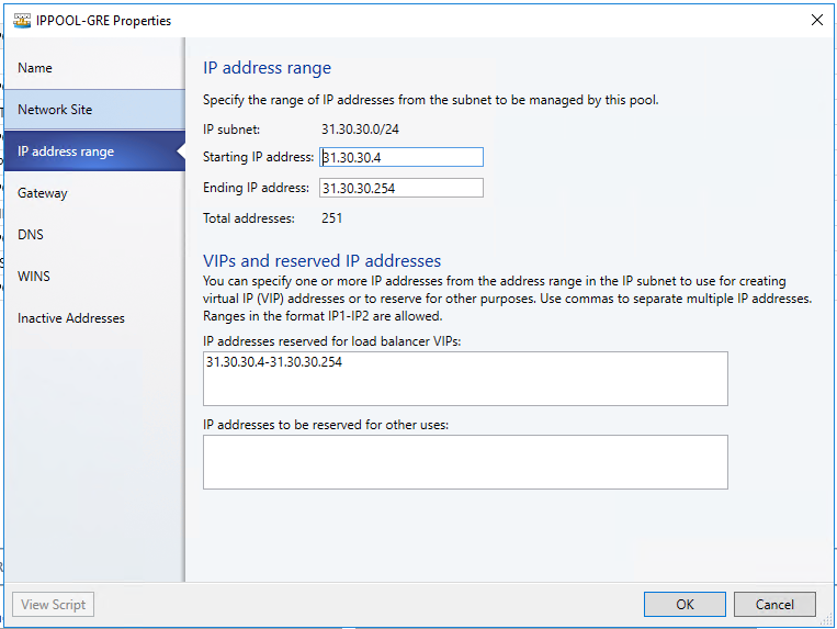
- In the IP addresses reserved for load balancer VIPs box, type the IP addresses range in the subnet. This should match the range you used for starting and ending IP addresses.
- You do not need to provide gateway, DNS or WINS information as this pool is used to allocate IP addresses for VIPs only via the network controller, so click Next to skip these screens.
- Review the summary information and complete the wizard
Import the Gateway service template
In the top of the left pane, in the Templates section, select Service Templates.
- In the ribbon at the top, click Import Template.
- Browse to your service template folder, select EdgeServiceTemplate Generation2.xml and click Next.
- This service template uses the following virtual machine configuration parameters. Update the parameters to reflect the your environment configuration.
Configuration parameters: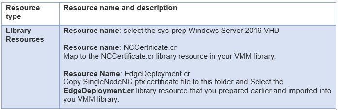
- Click Next.
- On the Summary page, click Import.
Configure the Gateway deployment
Use the following procedure to deploy a Gateway service instance.
- Select the EdgeServiceTemplate Generation2.xml service template and click Configure Deployment to begin. Type a name and choose a destination for the service instance. The destination must map to a Host Group that contains the hosts configured previously for gateway deployment purposes.
- In the Network Settings section, you must map the networks as MGMT
- Click OK.
- After you are done mapping the destination and network settings, Click OK.
- The Deploy Service dialog appears. It is normal for the virtual machine instances to be initially red. Click Refresh Preview to automatically find suitable hosts for the virtual machine.
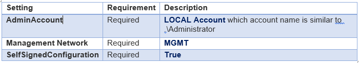
- On the left side of the Configure Deployment window, there are several settings that you must configure. The table below summarizes each field:
Deploy the Gateway service
After you configure these settings, you can click Deploy Service to begin the service deployment job. Deployment times will vary depending on your hardware but are typically between 30 and 60 minutes.
If the gateway deployment fails, ensure you delete the failed instance of the service using the following steps before you retry the gateway deployment.
Remove a failed gateway instance
- Open the VMM console.
- Select VMs and Services.
- Click All Hosts and select the Services
- Delete the failed Gateway Service instance.
Configure the Gateway Manager Role
Now that the gateway service is deployed, you can configure its properties and associate this with the network controller service.
- Open the Fabric
- Click Network Service to display the list of network services installed.
- Right-click your network controller service and select Properties.
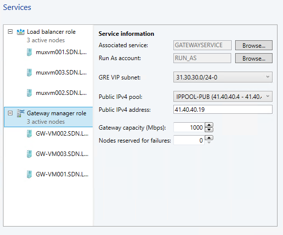
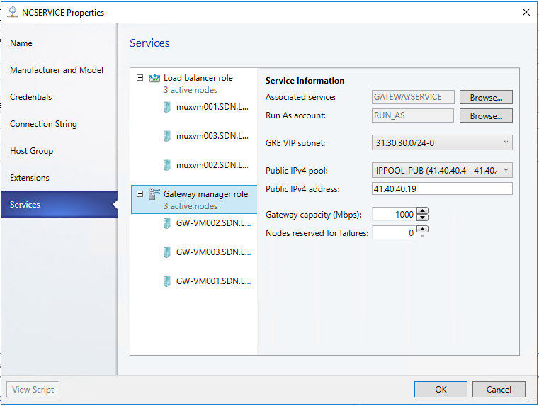
- Click the Services tab and select the Gateway Manager Role in the services panel.
- Find the Associated Service field under Service information and click Browse.
- Select the gateway service instance you created earlier and click OK.
- Select the Run As account that will be used by network controller to access the gateway virtual machines. This account should have admin privileges on the gateway VMs.
- In GRE VIP subnet, select the VIP subnet that you created previously.
- In Public IPv4 pool, select the Public IP Pool you configured during the SLB deployment.
- Public IPv4 address, provide an IP address from the previous pool.
- Configure the Gateway Capacity in Gateway Capacity 1000
- Configure the number of reserved nodes for back-up in Nodes for reserved for failures field
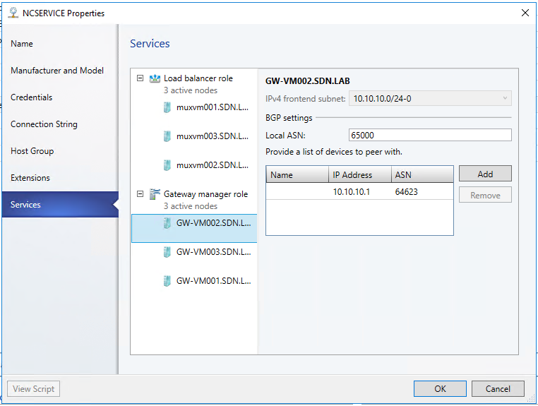
- You need to configure individual gateway virtual machines now. Click each gateway virtual machine and:
- Select the IPv4 Frontend Subnet. Transit
- Specify the local ASN. anything
- Optionally add the peering device info for the BGP peer
- Click OK
The Service instance that you deployed is now associated with the Gateway Manager role, and you should see the gateway virtual machine instance listed under the Gateway Manager role.
Validation by finishing exercise 3 and 4
Exercise 3 Description: Create IPSEC S2S VPN to a Remote site
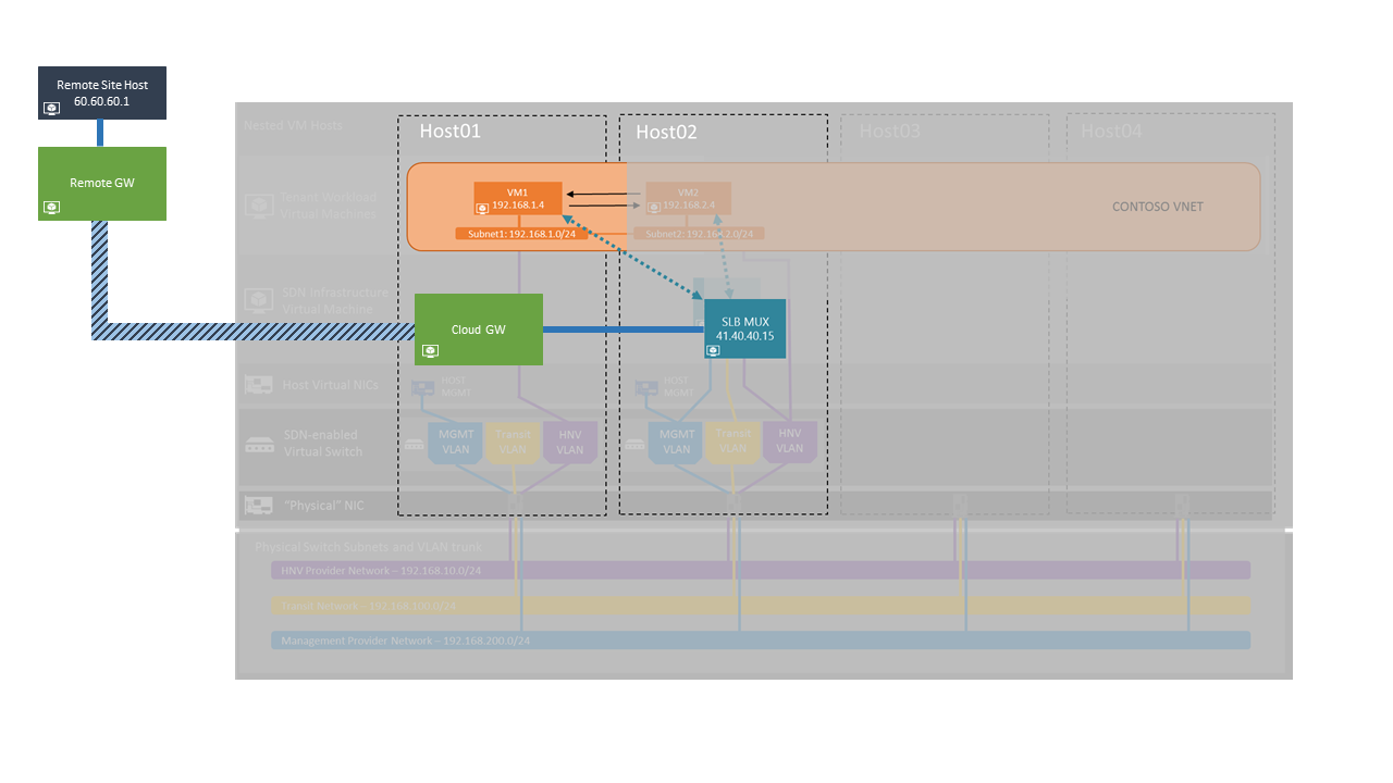
In this exercise, you will be creating a Site-to-site VPN connection between the SDN and a remote site. The image below gives a high-level view of the topology we will be creating in this exercise.
- Open System Center Virtual Machine Manager (SCVMM) Console
Double-click the Virtual Machine Manager Console icon on the Desktop.
Click “Connect” - Open Tenant VM Network property
Select “Client VMs and Services” in the bottom-left hand side of the VMM console
Click on “VM Networks”
Right Click the VM Network you created in Exercise 1, step 4 (E.g. “CONTOSO”)
Select “Properties” from the popup menu after your right click. - Setup the VPN connectivity
Select “Connectivity” from the left navigation tabs.
Check “Connect to another network through a VPN tunnel”
Leave “Enable Border Gateway Protocol (BGP)” unchecked
Check “Connect directly to an additional logical network”
Select the “Direct routing” radio button.
Make sure the Gateway Service is selected as “SingleNodeNCService”
Don’t click “OK” for now. - Setup VPN Connections
Select “VPN Connections” from the left navigation tabs
In the subnet text field; enter 10.254.254.0/29 (this is a rarely used range)
Click on “Add” and choose “Add IPsec tunnel”
In the “Name” text input, Give the IPSEC tunnel a name (eg. “IPSEC-VMM”)
In the “Remote endpoint” field, input “50.50.50.1”—this is the IP of the remote site that was pre-created for this exercise
Do not check “Limit bandwidth available for this VPN connection”
Click on “Authentication”
Select the first radio button option, “Authenticate using the following credentials”
For “Run As account:”, click on “Browse”
Select “IPSECACCOUNT” as the “Run As” account, then click “OK”
Create an “IPSECACCOUNT” as the “Run As” account; please do not make your own account. chose any username, but you have to use "User@123" as the password
Click on “Routes”
Click on the “Add” button to add a subnet
In the Subnet text field, input “60.60.60.0/24” which is configured in the remote site
Click “OK”. This may take a few seconds to complete. - Make sure the VMM job is finished
Click on “Jobs” in the bottom-left hand side of the VMM console
Make sure the running jobs have finished successfully (all running jobs should have a “Completed” status)
Setup Gateway on the remote site on Remote VM
Go to Remote VM
Right click Windows Start Menu , select Run and type “rrasmgmt.msc” to open the “Routing and Remote Access” menu.
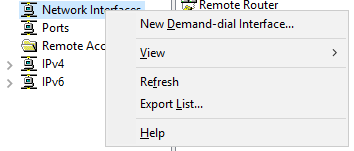
Right click Network Interface and select “New Demand-dial interface…”
Type “IPSEC-S2S” as the name and click “Next”
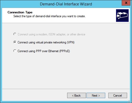
Select “Connect using virtual private network (VPN)”. Then click “Next”
In the VPN type, select “IKEV2” , and click “Next”
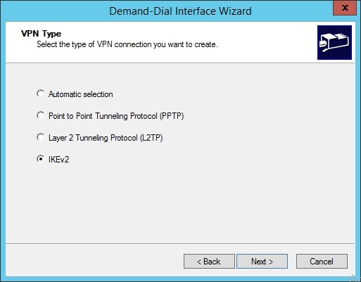
Input “40.40.40.20” as the VIP of the gateway service
Check “Route IP packets on this interface”, Click “Next”
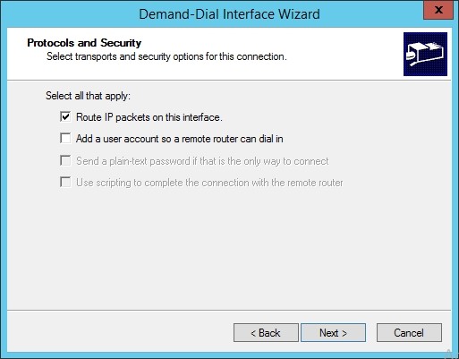
Input “192.168.1.0/24” as the Subnet of the Tenant VM Network you will connect to. Click “Next”.
Click Next on the Dial-out Credentials
Click Finish
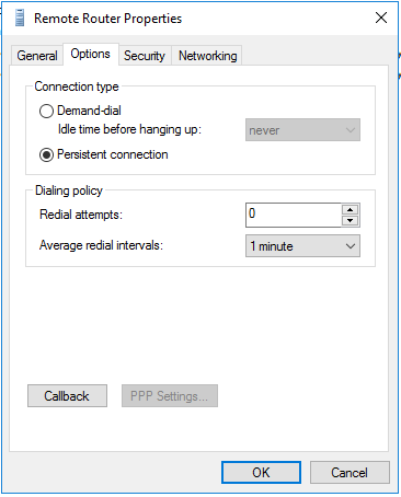
Right click on the created remote router to Open its “Properties”
In the options tab page, select “Persistent connection” as the connection type and click “OK”.
Establish the S2S VPN connection
After you have logged in to the remote site gateway, double click the shortcut “RRAS Management Console” on the desktop to open it.
In the left menu of the RRAS Management Console, click on “Network interfaces”
Right click on “Remote Router”
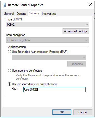
Click “Property” -> “Security”
In the “Key” input text field, remove all the existing stars “*****” there.
Input “User@123”
And click OK.
Right click on “Remote Router”
Click “Connect”
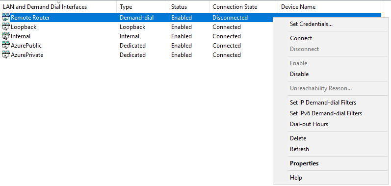
After a short delay around 5-6 seconds, you will see the Remote Router Connection State change from “Disconnected” to “Connected”.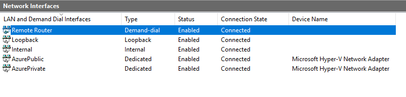
Now the S2SVPN is connected.Validate the S2S VPN connection
Select the VMM console (it should be minimized in the taskbar)
Click on “VM and Services” in the bottom-left hand side of the VMM console
Click on “All hosts”
In the right VMs window, locate your first created VM - “VM1”
Right click on the VM and select “Connect or View”
Choose “Connect via Console”
The Virtual Machine viewer window will now appear
Click on the “Ctrl-Alt-Del” (button in upper left-hand corner) then use “.\Administrator” as the username and “ !!123abc” as the password to login
Press the Windows key and type “Internet Explorer” then press Enter to open the browser
In the launched Internet Explorer window, input https://60.60.60.1 in the address bar and press Enter
You should see a “Congratulations!” web page.You have now finished the IPSEC S2S VPN successfully!
Exercise 4 Description: Create GRE Connection to a Remote site
In this exercise, you will be creating a GRE connection between the SDN and a remote site.
Use the following steps to configure a S2S GRE connection:
Right Click CONTOSO VM Network and click Connectivity.
Select Connect to another network through a VPN tunnel.
Select your Network Controller Service for the Gateway Device.
Select the VPN Connections
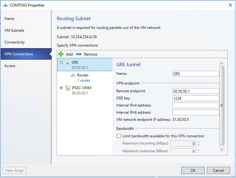
Click Add and then select GRE type connection.
Type a subnet as shown in the following diagram. This subnet is used to route packets out of the VM Network. This subnet does not need to be preconfigured in your datacenter.
Type a connection name. The name used in the example screenshot is GREVPN.
Type the IP address of the Remote endpoint: 50.50.50.1
Type the GRE key - 1234
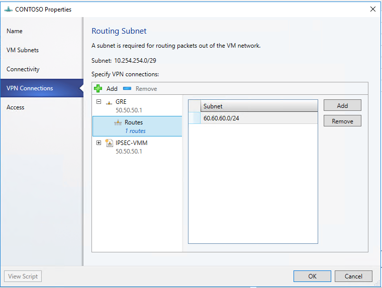
Select the Routes
Add "60.60.60.1" to the Subnet and click OK
Click on “Fabric" on the left navigation
Click on "Network Service", and double click on the "Gateway Service" under "Network Controller Service"
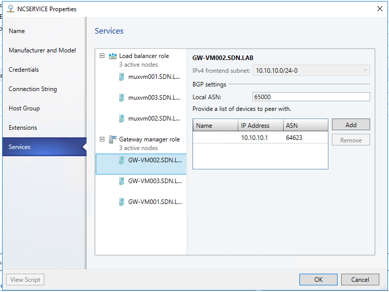
Configure the Gateway Service Information as the following -
Then configure each of the Gateway node as the following with Local ASN : 65000, PEER IP Address: 10.10.10.1 and ASN 64623
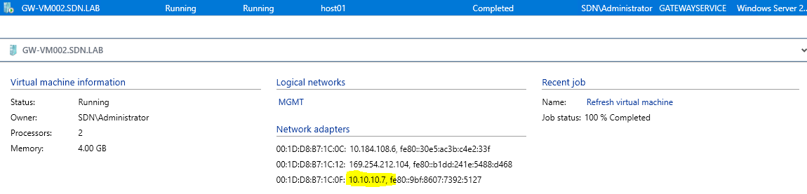
Go to VMs and Services , click on All Hosts
Check each of the Gateway VM's Transit IP Address, you will need these IP addresses in the next steps.
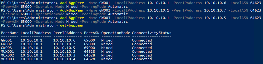
Go to RRAS VM , open the PowerShell console
Run the following PowerShell to add BGPPeer for each of the gateway , the "PeerIPAddress" should be the IP address of the Gateway Node Transit IP you just found out in the previous step. When finished, run Get-BGPPeer to check if they are connected.
Go to Remote VM , open the PowerShell console
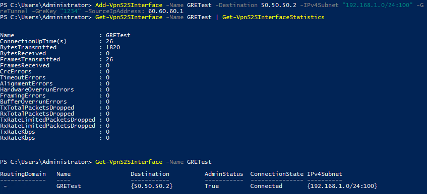
Run the following Powershell to add a new VPNInterface for GRE connection , when finished , use "Get-VPNS2SInterface" cmdlet to check the status and connectivity
Validate the GRE Connection
Select the VMM console (it should be minimized in the taskbar)
Click on “VM and Services” in the bottom-left hand side of the VMM console
Click on “All hosts”
In the right VMs window, locate your first created VM - “VM1”
Right click on the VM and select “Connect or View”
Choose “Connect via Console”
The Virtual Machine viewer window will now appear
Click on the “Ctrl-Alt-Del” (button in upper left-hand corner) then use “.\Administrator” as the username and “ !!123abc” as the password to login
Press the Windows key and type “Internet Explorer” then press Enter to open the browser
In the launched Internet Explorer window, input https://60.60.60.1 in the address bar and press Enter
You should see a “Congratulations!” web page.You have now finished the GRE connection exercise successfully!