Deploying SDN on One single physical host using VMM – Software Load Balancer
Create “Transit” logical network
- From the VMM console, start the Create logical network Wizard.
- Input “Transit” as the name and optional description for this network and click Next.
- On the Settings page, ensure you select One Connected Network. Check Create a VM network with the same name box to allow virtual machines to access this logical network directly and the Managed by the network controller box then click Next.
- On the Network Site panel, add the network site information for your subnet.
- Review the Summary information and complete the logical network wizard
Create an IP address pool for Transit logical network
The IP Pool should be – 10.10.10.0/24 , Vlan ID is 10, Gateway is 10.10.10.1
Don't include the first IP addresses of your subnet in the IP pool you are about to create. For example, if your available subnet is from .1 to .254, start your range at .2.
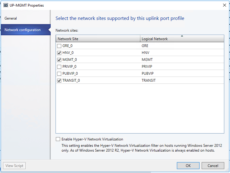
After you create the Transit logical network, ensure you associate this logical network with the Management switch uplink port profile you created during the network controller deployment.
Private VIP logical network
- Start the Create logical network Wizard.
- Input “PrivateVIP” as the name and optional description for this network. Click Next.
- On the Settings page, ensure you select One Connected Network. check Create a VM network with the same name box to allow virtual machines to access this logical network directly and the Managed by the network controller box then click Next.
- On the Network Site panel, add the network site information for your Private VIP logical network.
- Review the Summary information and complete the wizard.
You can now proceed to create IP pools for the Private VIP and Public VIP logical networks you created earlier.
Create VIP address pool in the Private VIP logical network
- Right-click the Private VIP logical network in VMM and select Create IP Pool from the drop down menu.
- Input “IPPOOL-PRIVATEVIP” as the name and optional description for the IP Pool and ensure that the Private VIP logical network is selected for the logical network. Click Next.
- Accept the default network site and click Next.
- Input 20.20.0/27 as the IP range
Important
Start your range on the second addresses of your available subnet. For example, if your available subnet is from .1 to .254, start your range at .2.
- In the IP addresses reserved for load balancer VIPs box, type the IP addresses range in the subnet. This should match the range you used for starting and ending IP addresses.
- You do not need to provide gateway, DNS or WINS information as this pool is used to allocate IP addresses for VIPs only via the network controller, so click Next to skip these screens.
- Review the summary information and complete the wizard.
Public VIP logical network
- Start the Create logical network Wizard.
- Input “PublicVIP” as the name and optional description for this network and click Next.
- On the Settings page, ensure you select One Connected Network. Check the Create a VM network with the same name box to allow virtual machines to access this logical network directly and the Managed by the network controller Also, select Public IP Address Network and then click Next.
- On the Network Site panel, add the network site information for your Public VIP network. This should include the Host Group and subnet information for your Public VIP network.
- Review the Summary information and complete the logical network wizard
To create an IP pool for Public VIP logical network
- Right-click the Public VIP logical network in VMM and select Create IP Pool from the drop down menu.
- Input name “IPPool-PUBLICVIP” and optional description for the IP Pool and ensure that the VIP network is selected for the logical network. Click Next.
- Accept the default network site and click Next.
- Choose a starting and ending IP address for your range.
- In the IP addresses reserved for load balancer VIPs box, type the IP addresses range in the subnet. This should match the range you used for starting and ending IP addresses.
- You do not need to provide gateway, DNS or WINS information as this pool is used to allocate IP addresses for VIPs only via the network controller, so click Next to skip these screens.
- Review the summary information and complete the wizard
Import the SLB/MUX service template into the VMM library.
- In the VMM console, navigate to Library.
- In the top of the left pane, in the Templates section, select Service Templates.
- In the ribbon at the top, click Import Template.
- Browse to your service template directory, select the SLB Production Generation 2 VM.xml file and follow the prompts to import it.
- This service template uses the following virtual machine configuration parameters. Update the parameters to reflect your environment configuration.
Configuration parameters:
Configure the deployment
Use the following procedure to deploy an SLB/MUX service instance.
To configure the deployment
- Select the SLB Production Generation 1 VM.xml service template and click Configure Deployment to begin. Type a name and optional destination for the service instance. The destination must map to a Host Group that contains the hosts configured previously.
- In the Network Settings section, you must map the networks as follows.
| Network setting | Value |
|---|---|
| TransitNetwork | TRANSIT |
| ManagementNetwork | MGMT |
After you are done with mapping the destination and network settings, the Deploy Service dialog appears. It is normal for the virtual machine instances to be initially red. Click Refresh Preview to automatically find suitable hosts for the virtual machine.
On the left side of the Configure Deployment window, there are a number of settings that you must configure. The table below summarizes each field:
Deploy the SLB/MUX service
After you configure these settings, click Deploy Service to begin the service deployment job. Deployment times will vary depending on your hardware but are typically between 30 and 60 minutes.
If the SLB/MUX deployment fails, ensure you delete the failed instance of the Service using the following steps before you retry the SLB/MUX deployment.
To remove a failed SLB/MUX instance
- Open the VMM console.
- Select VMs and Services.
- Click All Hosts and select the Services
- Delete the failed SLB/MUX Service instance.
When the service deployment job has completed, verify that your service appears in the VMM console:
Open the VMs and Services workspace.
- Click Services in the ribbon.
- Verify that your SLB MUX service instance appears in the VM Network Information for Services
- Right-click the SLB MUX service and select Properties from the menu.
- Verify that the state is Deployed.
If you want to scale-in or scale-out a deployed Software Load Balancer Service instance, see System Center: Virtual Machine Manager Engineering Blog.
Configure the SLB role and SLB/MUX Instance Properties
Now that the service is deployed, you can configure its properties. This involves associating the SLB service instance that you deployed with network controller, and then configuring BGP peering between the SLB/MUX instance and a ToR switch or a BGP router peer.
Associate the SLB/MUX Instance with SLB Manager service
- Open the Fabric
- Click Network Service to display the list of network services installed.
- Right-click the network controller service and select Properties.
- In the Wizard, Select the Services tab, and then click Load Balancer Role.
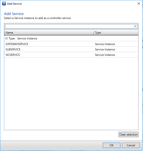
- Find the Associated Service field under Service information and click Browse.
- Select the SLB/MUX service instance you created earlier and click OK
- Choose the appropriate Run as Account
- For the Management IP address, use the desired IP address from the Private VIP pool you created earlier.
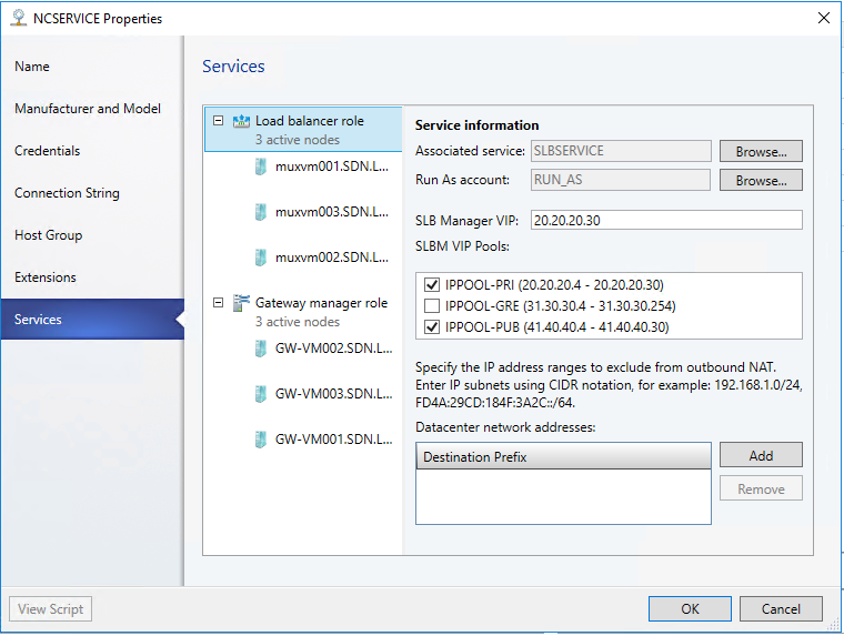
- Optionally specify the IP address ranges to be excluded from the outbound NAT.
- Click the SLB/MUX instance listed under Load Balancer Role in the wizard.
- Type the local ASN for your datacenter and details for the devices or BGP peers the SLB/MUX can peer with. You should use the Transit network for BGP peering. Do this for all three MUX.
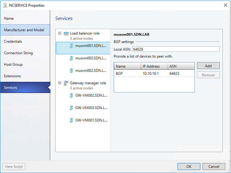
- When finished, press OK. Then Make sure associate service instance with fabric role.
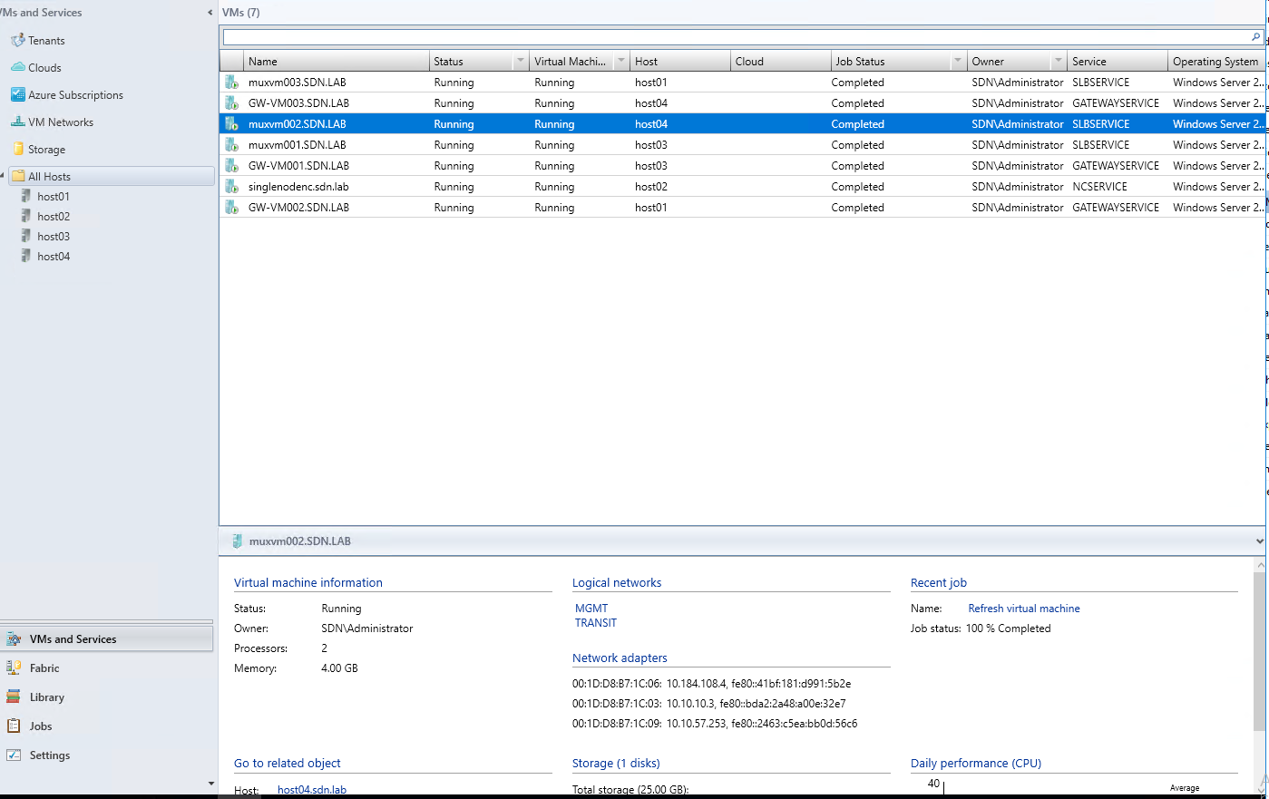
- Click on VMs and Services tab
- Click on All Hosts, locate to the MUX
- Check the Transit IP of each MUX , these IPs will be used in the next steps
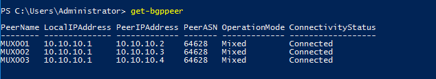
Create and configure BGP Router on RRAS VM
Open RRAS VM
Open the PowerShell CMDLet and using the following scripts to create and configure the BGP router.
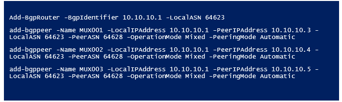
Run Get-bgppeer to verify the connection
Validation by finishing exercise 2
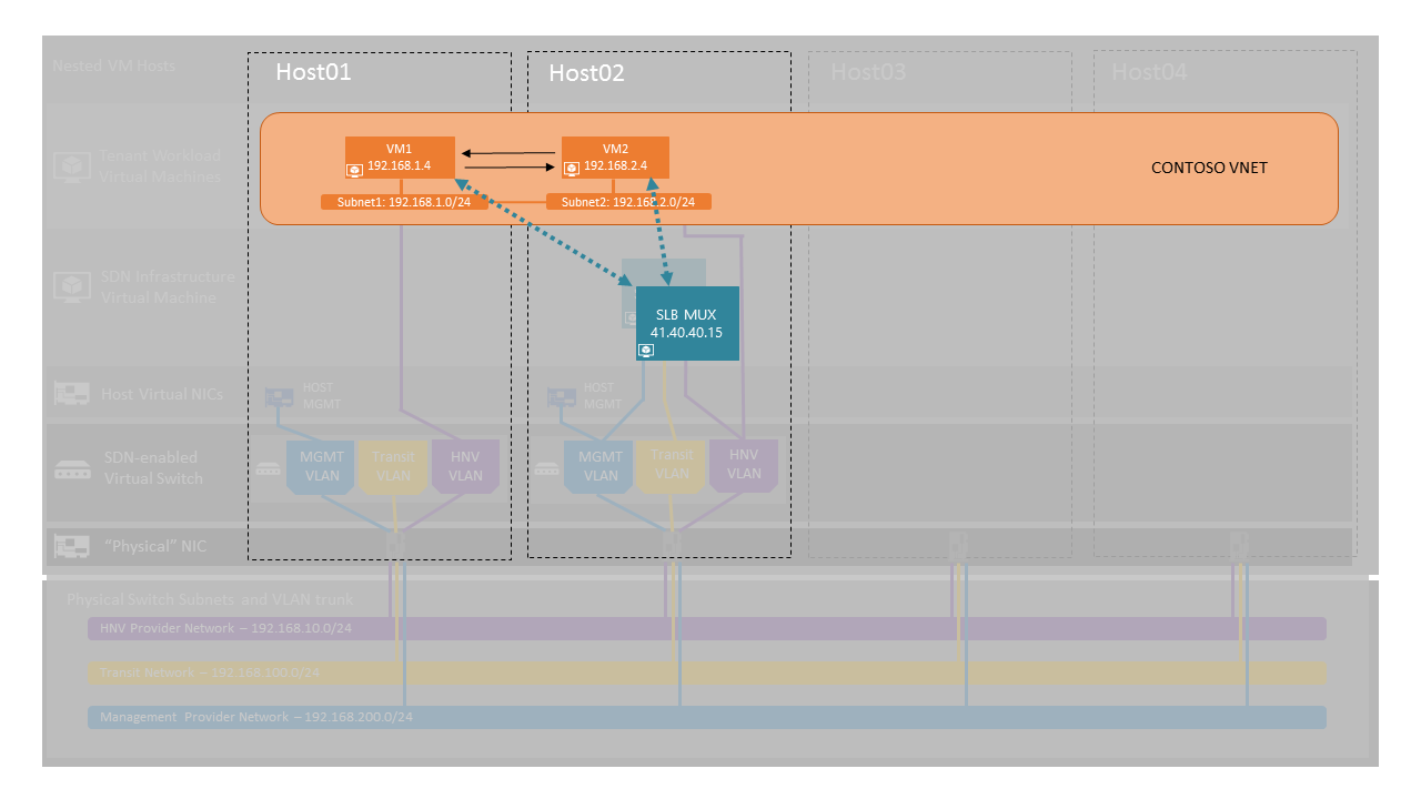
Exercise Description: Create a SLB VIP
In this exercise, you will be creating a public VIP on the Software Load Balancer (SLB) using SCVMM and PowerShell through which you can access a website on your virtual network.
The image below gives a high-level view of the topology we will be creating in this exercise.
Tasks
- Open System Center Virtual Machine Manager (SCVMM) Console
If it’s already opened, just go back to the console. If it’s not, double-click the Virtual Machine Manager Console icon on the Desktop.
Click “Connect” - Open Create a VIP Template Wizard
Click on “Fabric” in the bottom-left hand side of the VMM console
Click on “VIP Templates” in the menu on the left-hand side
Click “Create VIP Template” in the Ribbon menu - Specify VIP Template Name and Port
Input “VIPTemplate” as the name and optionally a description for the VIP Template
Specify the “Virtual IP port” (public facing) value of 80 and “Backend port” (on tenant VMs) value of 80
Click “Next” - Specify a Template Type
Select “Specific template” and navigate to: - Manufacturer: “Microsoft”
- Model: “Microsoft Network Controller”
Click “Next” - Specify Protocol Options
Select “Custom” protocol and type in value of TCP
Click “Next” - Skip Specify Persistence
Leave the “Enable Persistence” checkbox un-checked
Click “Next” - Select a Load Balancing Method
Click the drop-down to choose a load balancing method and select “Round Robin”.
Click “Next” - Skip specify a health monitor
Click “Next” - Confirm Settings and Create VIP Template
Click “Finish” to Create the VIP Template
Check in “jobs” to see if the task creation is finished. - Run the CreateTenantVIP PowerShell function
Open the “Start menu” and right click on “Windows Powershell ISE”
Choose “More” > “Run As Administrator”
In the “Powershell ISE” window, select menu “File” > “New”
Copy and Paste all the following script to the file
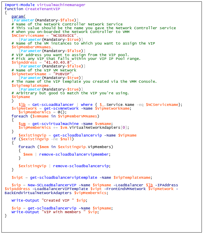
- Save the file as Name “CreateVIP”
Click the green arrow to “Run Script”
The script may take a moment to run (the cursor in the PowerShell execution window will be inactive until the script is complete).
Create a Tenant VIP
Run the following command in the PowerShell execution window.

- Validate Load Balanced VIP
Open “Internet Explorer"
Enter the IP address, “41.40.40.8” into the address bar
You should now see the default Windows Server Welcome page - Congratulations! You just created an externally facing VIP that load balances across multiple VMs.