Note
Access to this page requires authorization. You can try signing in or changing directories.
Access to this page requires authorization. You can try changing directories.
Guest post by Frances Tibble Software Engineer at Microsoft
[ I’m the beginner in Quantum Programming.]
Frances graduated with a degree in Computing from Imperial College London having completed a final year project with Microsoft Research. Frances now works as a Software Engineer for Microsoft focusing on Machine Learning and High Scale Data… and as of this blog post, Quantum Computing.
So maybe you heard the announcement of the Quantum Development Kit and thought it sounded insanely cool… Then you had a look and realized you know next to nothing about quantum mechanics. Yep, me too.
But that’s okay. In about 30 minutes you’re going to know enough about qubits, superposition and entanglement to write your very first quantum program, and most importantly, have a reasonable idea of what it means. Sounds smashing.
Contents of this blog
- Back to Basics
- Measuring a Qubit
- Quantum Gates
- Important Gates
- Multiple Qubits
- Another Important Gate
- Bell State
- Writing a Quantum Program
- What’s next?
- Appendix
- Further resources
Back to Basics
Unless you’re a super low-level programmer, it’s easy to forget that the programs we write are essentially just manipulating a bunch of 0s and 1s stored in our ‘classical’ computer. These are discrete, binary states. Quantum computers however operate on continuous states – that’s part of what makes them so powerful.
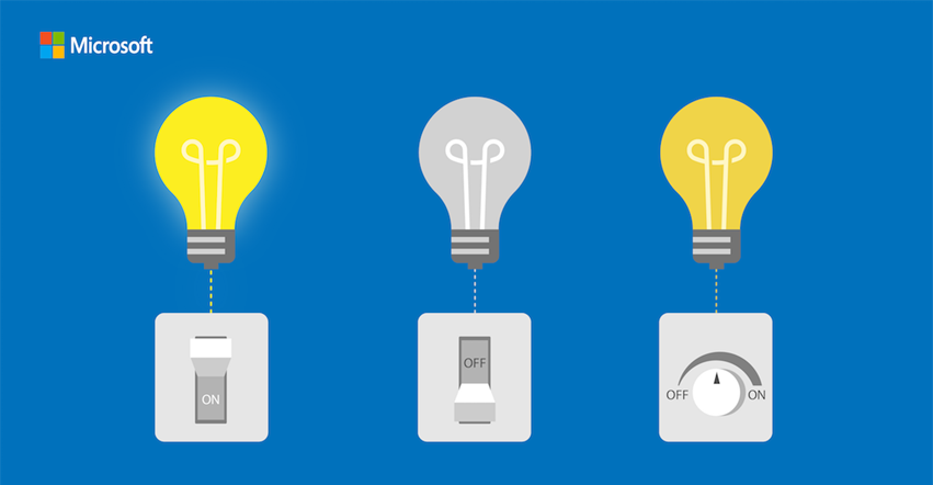
So instead of a classical bit being ‘on’ or ‘off’ like a light switch, in a quantum computer we have qubits, which are more like a dimmer switch, being any possible combination of ‘on’ and ‘off’ in between.
We can notate the two qubit states using Dirac notation which equates to these vectors:
If we add the two states together, we can express any possible combination of |0〉 and |1〉, and in quantum mechanics this is called a superposition. The notation for that looks like this:
|ψ⟩ = α |0〉 + β |1〉
Here α and β are kind of like probabilities with the minor difference that they are complex numbers. It doesn’t matter if you think of them as real numbers; however if you do, then remember that they'll sometimes be negative, and that the sum of their squares is always 1.
Measuring a Qubit
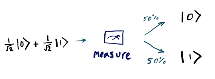
Now quantum states are weird. If you “look” at a qubit, it immediately collapses its state… a bit like looking at your bed after a long day. What I mean by that is, if we have a qubit that is in a superposition and we measure it, it’s either going to collapse to the |0〉 state or the |1〉 state (we can’t measure both at the same time!). After measurement, we effectively lose the prior values of α and β .
Because of that, when we measure a qubit we talk about the result we get in terms of probabilities. In general, a qubit when measured will give ‘|0〉’ with probability , and ‘|1〉’ with probability
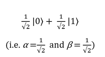
  . Let’s have a look at an example - say we had the following qubit:
If we measure the qubit we are likely to get the outcome ‘0’ fifty percent of the time, because  , and its post-measurement state will be |0〉 (i.e. α =1 and β=0). Similarly, we are likely to get the outcome ‘1’ fifty percent of the time, for the same reason, and its post-measurement state will be |1〉 (i.e. α =0 and β=1).
This can seem confusing at first (and the second, third, and fourth time!). The main point here is that these probabilistic quantum states can be used for computation and in some cases, this is much more efficient than classical systems due to their ‘quantum weirdness’. Next, we’re going to look at how we can manipulate these qubits for computation just like you can with classical bits.
Quantum Gates
We’re back in familiar territory. In classical computing we use logic gates to operate on bits, and likewise we can use quantum gates to operate on qubits. Think of the NOT gate, which takes 0 → 1 and 1 → 0. A quantum NOT gate bears some resemblance to its classical brother, as it takes |0〉 → |1〉 and |1〉 → |0〉. So a qubit in the state α |0〉 + β |1〉 becomes α |1〉 + β |0〉 after such a gate has operated on it. The not gate can be written as a matrix, X, which swaps the roles of 0 and 1 in the state
As we can see, X|0〉 = |1〉 and X|1〉 = |0〉:
Because |0〉 and |1〉 are defined in vector form as  and
and , you can think of the first column of X as the transformation applied to |0〉 and the second column as the transformation applied to |1〉.
Now this doesn’t seem all that different to what we’re used to. But I want to remind you of what we found in the previous section, that the measurement of a qubit is probabilistic. As we know from basic statistics, all probabilities sum to one. As a result, we have the condition that  for a quantum state α |0〉 + β |1〉.
A consequence of this is that there are some constraints on what gates we can have in the quantum world. And one of them is that this normalization condition on the quantum states,  , should hold both before and after the gate has acted. In terms of matrices, this condition will hold if a matrix is unitary.
I’m about to tell you what unitary means in maths speak, if we read it really quickly we can get to the next sentence. A gate is unitary if , where  s obtained by transposing and then complex conjugating
  is the two by two identity matrix. In plain English, it means that the transformation doesn’t change the length of the vector. Keeping the length constant is the same as ensuring that all the probabilities add up to 100%. Having probabilities add up to 200% or 25% would make no sense and using unitary matrices guarantees at least this type of craziness is off the menu in the quantum world.
But we can breathe a sigh of relief – this is our only constraint. Some classical gates don’t have quantum equivalents for this reason, but there are some new ones that crop up too, and we’re going to look at some important ones next.
Important Gates – Bill, Z and Hadamard
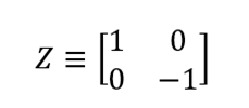
The following gates you’ll see in our first quantum program, so make a mental note. The Z gate is nice and simple, it leaves |0〉 unaltered and makes |1〉 negative. That can be written as a matrix like this,
which transforms the qubit states from |0〉→|0〉 and from |1〉→ -|1〉. (Remember, the first column corresponds to the transformation applied to |0〉, and the second column to |1〉.)
Then we also have the Hadamard gate which creates a superposition between the |0〉 and |1〉 states, similar to those seen previously. And that can be written as a matrix like this,
which transforms the qubit states from  and
and .
.
If you’re interested in learning more about unitary matrices, and how to visualize these gates have a look at the Further Resources section where I’ve listed some useful material.
Multiple Qubits
Time for some more familiar stuff. In the classical world we can have multiple bits, such as 00, 01, 10 and 11. In quantum computing we can similarly have |00〉, |01〉, |10〉 and |11〉. We can describe the two qubits using a vector,
Just like before, the measurement result of ‘00’ for example, occurs with probability  ,
,
‘01’ with probability  , and so on.
Now say we wanted to measure the first qubit (instead of both), the measurement result of 0 occurs with probability  . And remember measurement changes the state, so afterwards the vector would now have a value of
You can see on the top line we’ve got rid of all the terms whose first bit was 1, since they weren’t consistent with the measurement being 0. The square root in the denominator renormalizes the vector so that the sum of the squared amplitudes is still 1, which we require for it to be a valid quantum state.
Another Important Gate
You’ve seen the NOT gate, next up we’ve got the CNOT gate, which stands for controlled-NOT. It takes two input qubits, the first is the control qubit, and the second is the target qubit. As you might have guessed, if the control is |0〉, then the target qubit is unchanged. If the control is |1〉, then a NOT is performed on the target qubit.
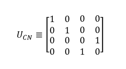
There are a few ways to think of CNOT. Like X, Z and H, we can show it in matrix form, U.
Looking at the columns of the matrix we can see that they correspond to the following transformations, |00〉→|00〉, |01〉→|01〉, |10〉→|11〉 and |11〉→|10〉. As with the other matrices we’ve looked at  , is unitary, meaning
 .
.
It can also be drawn like this, where the control bit is on top and the target bit is at the bottom:
Looks like something you might find in the Tate Modern.
Bell States
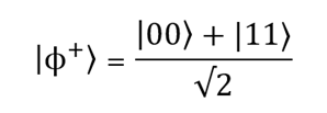
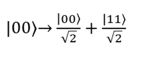
These get a whole section of their own. The Bell states (there are four of them). You’ll see one of them (|ϕ+⟩) appear in the quantum program a little later, so here it is:
Suppose we were to measure the first qubit, we’re going to get |0〉 with probability  leaving the post-measurement state |ψ’ ⟩=|00〉, or |1〉 with the same probability, 0.5, and a post-measurement state |ψ’ ⟩=|11〉. In case you were interested, here’s the complete set of four Bell States (which represent the simplest examples of quantum entanglement):
Suppose instead that we had measured the second qubit - using the same logic it would leave the post-measurement state |00〉 or |11〉. If we then decided to measure the first qubit, the probability is no longer a half, we’re going to get |0〉 with probability 1 or 0 depending on the post-measurement state. The key point here is that these outcomes are correlated. This was first noticed by Einstein, Podolsky and Rosen (which is why you might see them called EPR pairs), with further progress made by John Bell.
One final thing, we can generate Bell states using a combination of a Hadamard gate followed by a CNOT. I think this is pretty cool. The Hadamard transforms the first qubit by putting it into a superposition, this is then used by the CNOT as a control to modify the target qubit. That is neatly described by the following circuit diagram:
If you want to see the working behind each of those transformations, take a look at the Appendix. For now, with our knowledge of qubit states, quantum gates, and Bell states, we’re ready to tackle our first quantum program.
Writing a Quantum Program
For this we’re going to follow along with the documentation here:
/en-us/quantum/quantum-writeaquantumprogram?view=qsharp-preview
The purpose of this tutorial is to get set up with the quantum development kit (steps 1-2), allocate a qubit and do some simple things like setting its value and measuring it (steps 3-5), then we’ll superpose a qubit (step 6), before entangling two qubits to create a Bell state or EPR pair (step 7).
I suggest you follow the tutorial linked above, and refer back to the steps listed here for tips and further clarification if you need it.
Step 1: Create a Project and Solution
Q# is hiding at the bottom of the list there.
Step 2 (optional): Update NuGet Packages
I did this but you may like to live dangerously.
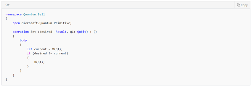
Step 3: Enter the Q# Code
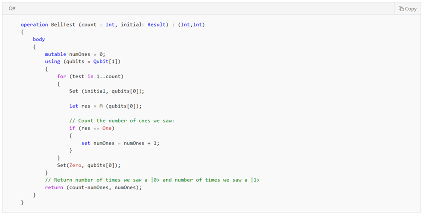
This operation sets our qubit to a desired state of Zero or One (that’s for us to choose). First we measure (M) the qubit, which collapses its state to either 0 or 1. If our measured state doesn’t match the provided desired state, we use the NOT gate, X, to flip it, otherwise we do nothing.
This little bit of code is going to test the previous operation we just wrote. It really isn’t a difficult program, it’s just verifying that the qubit was set to the value we wanted.
To do that, it’s going to loop count number of times and tot up how many One states we observed, and it stores that in the numOnes variable.
The Qubit[1] syntax simply allocates one qubit to the qubits array, which we index at 0. If we wanted to allocate two qubits (which we’ll do later), we’d use Qubit[2] and index qubits at 0 and 1.
In the for loop we set the qubit we’ve allocated to some initial value One or Zero (we do this explicitly in the Driver.cs file coming up). We measure that, and then count if the result was One. We then return how many One and Zero states we saw. We also set the qubit to Zero at the end, so it is left in a known state.
Step 4: Enter the C# Driver Code
In this driver code we construct the quantum simulator, we create an array of initial values we want to test, being Zero and One. We run the simulation with a count of 1000, and then print the results for debugging using System.Console.WriteLine.
Step 5: Build and Run
All being well, you should have this output. This means that when we set the initial qubit to Zero and repeated this a thousand times we correctly counted 1000 |0〉s, and the same when we set the initial qubit to One.
Step 6: Creating Superposition
Now we’re working up to something a bit more exciting. Here we flip the qubit using a NOT gate.
Then we run the program again, and we see that the results are reversed.
We then replace the NOT gate with a Hadamard gate (H). As we know, this places the qubit in a superposition, where it is in a probabilistic state of both |0〉 and |1〉 simultaneously.
Running the program again we get some interesting results.
We get |0〉 roughly half the time and |1〉 half the time.
Step 7: Creating Entanglement
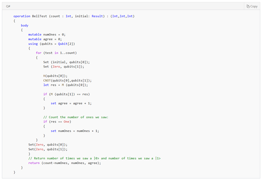
We’re going to make a Bell state now. Looking at the code below, we begin by allocating ourselves two qubits using the Qubit[2] syntax. The first qubit (x in our earlier circuit diagram) we set to some initial value, and the second qubit (y in our diagram) we set to Zero. This is akin to having an input of either |00〉 or |10〉, depending on 
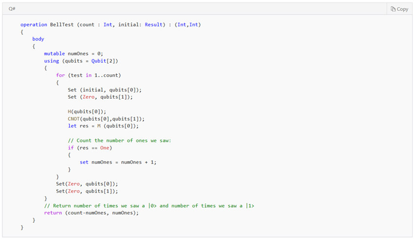
Following the circuit diagram, we apply the Hadamard gate to the first qubit, qubits[0], which puts it in a superposition. We then apply the CNOT gate (using qubits[0]as the control qubit and qubits[1] as the target) and measure the result.
Before we go into the results we expect, let’s just have a quick recap on the behaviour of our Bell state. When we measure the first qubit, we’re going to get |0〉 with probability  , leaving the post-measurement state |ψ’ ⟩=|00〉, or |1〉 with the same probability (0.5), and a post-measurement state |ψ’ ⟩=|11〉. So then when we measure the second qubit, it’s going to be |0〉 if the first qubit was |0〉, or |1〉 if the first qubit was |1〉. In our results we’re looking for the second qubit’s measurement to ‘agree’ with the first if we’ve successfully entangled the two qubits.
You can see that little piece of code in the if statement that we’ve added below, where we check if the measurement of qubits[1] is equal to the result of measuring qubits[0].
Before we can check the results we need to make a final modification to the Driver.cs file, which is to add our agree variable.
And now we’re ready to run the program. What we see is when the first qubit is initialized to Zero (i.e our input is |00〉), the Hadamard gate puts it in a superposition, so that upon measurement it is |0〉 fifty percent of the time, and |1〉 fifty percent of the time – which you can see by the count of 0s and 1s. If the second bit was unaltered by the measurement of the first bit, it would remain |0〉 and so would only agree 499 times.
However we can see that the second bit mirrored the value of the first bit exactly – it was |0〉 (about) fifty percent of the time, and |1〉 fifty percent of the time - resulting in the measurements agreeing 1000 times. This is exactly what we expect to see from Bell states!
And we’re done! You’ve just completed your first quantum program and if you got this far that hopefully means you understood what you were doing. Time for a celebratory cup of tea.
What’s next?
There’s a lot of samples on GitHub which you can find here: https://github.com/Microsoft/Quantum/tree/master/Samples
Next up in this blog series I’ll be explaining the background of quantum teleportation and working through the code sample.
Also check out Anita’s blog for a more in-depth look at quantum gates (Anita is amazing). https://blogs.msdn.microsoft.com/uk_faculty_connection/2018/02/06/introduction-to-quantum-computing/
Further resources
There were a few resources I found extremely helpful and I suggest you read if you want to go into more depth. The first is ‘Quantum Information and Quantum Computation’ by Nielsen and Chuang. The second is the SDK documentation by Microsoft: /en-us/quantum/quantum-concepts-1-intro?view=qsharp-preview
Learn more at the Microsoft Quantum website: https://www.microsoft.com/en-us/quantum/
Download the Quantum Development Kit: https://www.microsoft.com/en-us/quantum/development-kit
Stay up to date with the Microsoft Quantum newsletter: https://info.microsoft.com/Quantum-Computing-Newsletter-Signup.html
Read about the latest developments on the Microsoft Quantum blog: https://cloudblogs.microsoft.com/quantum/
Twitter: https://twitter.com/MSFTQuantum
Facebook: https://www.facebook.com/MicrosoftQuantum/
I could make another blog post on other resources if readers would find that helpful (leave a comment!).
Appendix – Bell states
We can generate Bell states using a combination of a Hadamard gate followed by a CNOT. The Hadamard transforms the first qubit by putting it into a superposition, this is then used by the CNOT as a control to modify the target qubit. That is neatly described by the circuit diagram
Let’s begin with the first case, if the input is |00〉. The first qubit |0〉 passes through the Hadamard gate producing  , whilst the second qubit is unchanged. So we have:
We then apply the CNOT gate which takes |00〉→|00〉 and |10〉→|11〉 so the state becomes:
Next the second case, if the input is |01〉. The first qubit |0〉 passes through the Hadamard gate producing , whilst the second qubit is unchanged. So we have:
We then apply the CNOT gate which takes |01〉→|01〉 and |11〉→|10〉 so the state becomes:
Then the third case, if the input is |10〉. The first qubit |1〉 passes through the Hadamard gate producing  , whilst the second qubit is unchanged. So we have:
We then apply the CNOT gate which takes |00〉→|00〉 and |10〉→|11〉 so the state becomes:
And finally the fourth case, if the input is |11〉. The first qubit |1〉 passes through the Hadamard gate producing  , whilst the second qubit is unchanged. So we have:
We then apply the CNOT gate which takes |01〉→|01〉 and |11〉→|10〉 so the state becomes:
Phew, all done. So, in summary, just as you can see in the table above, we have:
Comments
- Anonymous
September 04, 2018
An excellent overview! You should put this on Medium.
