Data Points
Designing an Entity Data Model
John Papa
Code download available at:DataPoints2008_02.exe(174 KB)
Contents
Understanding the EDM
Building an EDM with the Wizard
Stored Procedures in the Entity Model
Windows on EDM
Derived Entities
Wrapping Up
The Entity Framework is an exciting new technology being developed for ADO.NET. It allows developers to view data using a logical model instead of a physical model, offering more flexibility. I gave a detailed overview of the Entity Framework (which is due in the first half of 2008) in the July 2007 installment of Data Points. If you're not yet familiar with the Entity Framework, you can read my overview at msdn.microsoft.com/msdnmag/issues/07/07/DataPoints.
At the heart of the Entity Framework is the Entity Data Model (EDM). The EDM defines the entity types, relationships and containers that developers interact with via code. The Entity Framework maps these elements onto the storage schema exposed by a relational database. The EDM is exposed to the Entity Framework through XML that defines the conceptual application model. The conceptual model may be defined separately, or together with XML that defines the actual storage schema along with XML that defines the mapping between the two. While it is possible (and sometimes necessary) to manually edit the XML, it is much easier to create and modify an entity model and mapping using the new visual Entity Data Model designer tool.
In this month's column, I will discuss how you can design an entity model using the new visual EDM designer tool and how you can modify the underlying XML that defines both the model and the mapping. I'll start by describing all of the pieces that interact within the Entity Framework (including LINQ) and will then discuss where the EDM fits. Furthermore, I will demonstrate how to create an entity model and associated mappings using the visual designer tool. Finally, I will introduce you to several windows that can help you modify and explore the model and mappings.
Throughout the column, I will explain the roles of the different components of the EDM, such as the EntityType and Association. The examples in this column demonstrate how to create basic entities. Note that all the examples in this column use Visual Studio® 2008 and the corresponding Entity Framework Beta 3 (these require separate installations). The database I am using is the revised Northwind database that comes with the samples for Beta 3.
Understanding the EDM
Before I dive into how to create and manage an entity model, let me first explain what the EDM is and how it interacts with the other elements of the Entity Framework. The Entity Framework consists of many pieces, including the EDM specification and associated mappings, APIs that interact with the EDM, and tools that help define and manage the entity model and mappings. Once you've designed an entity model, you can write code against it using the different APIs, such as the EntityClient provider, or Object Services (including LINQ to Entities).
The EntityClient data provider has a similar model to traditional ADO.NET objects, as it uses EntityConnection and EntityCommand objects to return a DbDataReader. The commands for the EntityClient provider are written using Entity SQL, which is similar to T-SQL, but, instead of operating on database objects, it operates on the entities defined in the entity model and on the objects materialized through Object Services. You can use Object Services to interact with the EDM, either by using Entity SQL or by using LINQ to Entities. Object Services allows you to take advantage of the conceptual model's generated classes, which offer features such as strongly typed objects and persistence (see Figure 1).
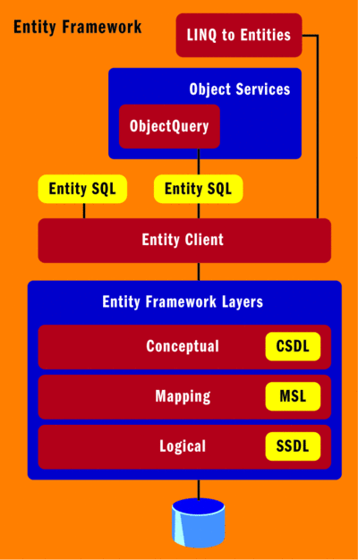
Figure 1** Entity Framework Overview **
These data access techniques allow you to interact with the conceptual entities defined within the entity model rather than the objects of a physical store such as a relational database. The data model and associated mappings are created by using either the visual designer tool or by manually editing the XML that defines them. The Entity Framework, shown in Figure 2, provides the glue between an application and its database. The EDM is used to describe the business entities through the conceptual entity model and the Entity Framework, through the mapping specification, then translates that to the physical storage of the database's tables, view, functions, and procedures.
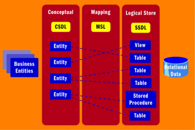
Figure 2** Entity Framework Connects an App to its Database **(Click the image for a larger view)
The application's entity model is described using the Conceptual Schema Definition Language (CSDL). CSDL is an XML Format that defines the entities and the associations between entities that developers will interact with via an API, such as LINQ to Entities. The Entity Framework also uses the Storage Schema Definition Language (SSDL), an XML format that defines the storage schema of the relational database and the Mapping Schema Language (MSL) to translate how the entities of the CSDL map to the storage schema described by the SSDL.
The CSDL is where the developer has the most influence since this is where the entities that she will most often interact with are defined. Figure 2 illustrates that some entities can be mapped directly to a single table in a database while others can be mapped to multiple tables. This entity determination is made by the development team based on the business model. The business model often operates on a single entity that exists in multiple physical tables in the database. You can also see in Figure 2 that an entity can be mapped to a database's view or an entity can obtain a method that will invoke a stored procedure. Entities can also be derived from other entities using inheritance in the conceptual model. These are just some of the ways in which the entity model can be designed using the EDM designer tools.
Building an EDM with the Wizard
To create an entity model, you start by adding a new ADO. NET Entity Data Model file to your project (see Figure 3). Once you do this, the Entity Data Model Wizard will prompt you to either generate a model from a database or begin with an empty model. Generating the model from existing database tables is a good way to start, as long as you have access to the database. Some development methodologies, such as domain driven design, advocate designing the entity domain model before you design the database. If this is your plan, you may want to create an empty model and then create your entities through the EDM visual designer. For my samples, I have built an entity model using the Northwind database as a starting point.
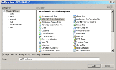
Figure 3** Add an EDM File to Your Project **(Click the image for a larger view)
The next screen of the wizard prompts you to enter the database connection information. Then, the wizard asks you to choose the database objects to include in the model. You can see in Figure 4 that I have selected all of the tables and stored procedures in the Northwind database, except for the ones that help with diagramming. The tables are initially mapped directly to entities and the stored procedures can be mapped to methods on the generated container.
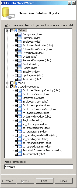
Figure 4** Choose Database Objects **
After you've specified the database objects that you want to include in the model, the EDM wizard generates the .edmx file that defines the model and mappings and adds the appropriate references to the project that are required by the Entity Framework. The .edmx file is an XML file that contains four major sections: information about the visual layout of the conceptual model in the designer, the conceptual model's CSDL, the mapping layer's MSL, and the physical model's SSDL. All of this information is contained in a single file.
The .edmx file's designer information is used to assist Visual Studio in laying out the entity model in the designer; this is only used at design time. The CSDL, MSL, and SSDL are used at compile time to generate classes that will represent the EDM.
Stored Procedures in the Entity Model
I've chosen to add the stored procedures to the entity model that I created, but the stored procedures have only been added to the SSDL definition. Since a stored procedure may interact with many different tables or other objects in a database, the Entity Framework does not automatically map the stored procedure to any one specific entity in the CSDL. If you want to create a method that maps to a stored procedure, you can do so by editing the XML in the .edmx file.
To create a method that returns entities of a given type, I first choose a stored procedure. For this example, I will add a method called GetTenMostExpensiveProducts, which will execute the Ten Most Expensive Products stored procedure, returning results as Product objects. Since the SSDL already describes the stored procedure as a Function element, the next step is to add the method in the CSDL. This can be done by adding the FunctionImport element as a child of the EntityContainer element:
<FunctionImport Name="GetTenMostExpensiveProducts"
  EntitySet="Products" ReturnType="Collection(Self.Products)"> </FunctionImport>
The Name attribute indicates the name of the method on the entity container. The EntitySet attribute indicates the EntitySet, and the ReturnType attribute refers to the EntityType that will be returned (or the collection of EntityTypes in this case).
The reference to Self in this example is an alias that refers to the current namespace, which is NWModel. Note that either NWModel or Self would work here.
If parameters are needed on the method, you can add them by including a <Parameter> tag. For example, if there was a CategoryId parameter on the stored procedure that I wanted to also include on the method, I could add it to the method by including the following XML element inside of the FunctionImport element:
<Parameter Name="CategoryId" Type="Int32" Mode="in"/>
But there is no parameter in my example, so I have skipped this step.
At this point, the CSDL defines the method, the entity type returned by the method, and the EntitySet to which the returned entities belong, while the SSDL defines the stored procedure. Now the CSDL has to be mapped to the SSDL so that the conceptual method knows what stored procedure to execute. This mapping is done by inserting the following FunctionImportMapping into the EntityContainerMapping section of the MSL:
<FunctionImportMapping FunctionImportName="GetTenMostExpensiveProducts"
  FunctionName="NWModel.Store.Ten_Most_Expensive_Products"/>
Here, the FunctionImportMapping element uses the FunctionName attribute to refer to the fully qualified name of the Function element in the SSDL. The FunctionImportName attribute refers to the name of the FunctionImport element in the CSDL.
Windows on EDM
Once the EDM has been designed and built, you can use various windows to examine the status of the entity model you have created. The Class View window (see Figure 5), which is not new, is helpful when you need to examine the objects that are available to be developed against. It will show, for instance, my new GetTenMostExpensiveProducts method on the NWEntities EntityContainer class, as well as all of the classes that the NWModel namespace contains. There will be a class representing each EntityType in the CSDL, plus a class for the main NWEntities model.

Figure 5** EDM in the Class View **
There are also some new windows that let you look into the entity model and the associated mappings. These include the Entity Data Model Designer, the Entity mapping Details window, and the Entity Model Browser window.
The Entity Model Browser shows all of the CSDL and SSDL components. These include the CSDL components EntityTypes, Associations, EntitySets, AssociationsSets, and Function Imports, as well as all of the SSDL elements.
The Entity Model Designer (see Figure 6) shows a layout containing the model that you've generated. The entity model can be viewed and manipulated from this designer, which represents all of the conceptual model's elements shown in a visual layout. Note that in Figure 6 there is a Product entity—this represents the Product EntityType in the CSDL. Each EntityType contains a list of properties, both scalar and navigational.
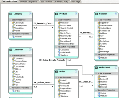
Figure 6** Entity Data Model Designer **(Click the image for a larger view)
Navigation properties are used to navigate across associations in the CSDL. The navigation properties become public properties on their EntityType class and are used to refer to another entity, or set of entities, associated with the original entity. For example, the Product EntityType has a navigation property named Categories, which will reference a Category entity for a particular Product entity instance. The Category EntityType also has a navigation property named Products. This exists so that with a Category entity instance, you can reference its associated Product entities.
The designer can be used to add, edit, or remove entity types, associations, scalar properties, and navigation properties. You can, for example, change the names of all of the EntityTypes to a singular form that is popular among developers when naming entities. Simply click the EntityType's name and edit the name in place. Or you can select the EntityType and change its name in the Properties window. For these examples, I renamed all EntityTypes to a singular format, which is reflected in Figure 6. After making this change, I also had to fix the XML I modified to add the Stored Procedure call as a method of the NWEntities EntityContainer. This is pretty simple, as I just had to update the code to refer to the Product EntityType (as opposed to Products), as shown here:
<FunctionImport Name="GetTenMostExpensiveProducts" EntitySet="Products"
  ReturnType="Collection(Self.Product)"> </FunctionImport>
This brings up an important point. It is a good idea to name your main elements, such as EntityType, EntityContainer, and Association, before you start modifying the data model. This will minimize the number of manual changes you'll need to make, as well as minimize any code changes you might need to make for code you may have already written against the data model. In case you run into problems, the Error List window is your best friend as it will very likely show you which elements have invalid references in the XML.
Finally, while the designer shows the conceptual model, the Entity Mapping Details window provides a means to view and edit the mappings (the MSL) between the EDM and the data store.
Derived Entities
The tools that help you design your entity model can also help you modify the model. One of the keys to object-oriented programming is the concept of inheritance. The EDM supports creating and modifying inherited entities both in the XML and visually in the EDM designer.
To demonstrate the task of designing inherited entities, I will create a DiscontinuedProduct EntityType based on the Product EntityType. The Product EntityType has a Boolean scalar property named Discontinued, which I will use as the Condition to be evaluated in determining a product's specific instance type. Using the Entity Model Designer, I right-click in the designer and choose Add | Entity from the popup menu. I then enter DiscontinuedProduct as the new entity name and select Product as the base entity (see Figure 7).
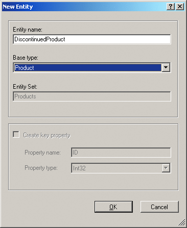
Figure 7** Creating an Inherited Entity **
In the next step, I want to define the differentiating factor between these entities using a Condition, so I select the Product EntityType in the designer and go to the Entity Mapping Details window. I then select the Discontinued property in the Column Mappings and remove the mapping. This removes the Discontinued property from both the Product and DiscontinuedProduct EntityTypes (When you create a Condition, the available expressions for the Condition must not already be used as a property). Next, I go to the Maps to Products section of the Entity Mapping Details window and add a Condition of Discontinued = 0. I then select the DiscontinuedProduct EntityType and add a Condition of Discontinued = 1.
Creating derived entities is really quite easy when you use this technique. If you want, you can also add additional properties to the derived entity beyond its base class's properties. When you create an instance of a DiscontinuedProduct in your .NET code and save it, the Entity Framework realizes that it must set the Discontinued column to a value of 0 in the database because of the Conditions that exist on it.
The Conditions are created in the EntityTypeMapping section of the MSL and simply enforce a filter on the retrieval of rows. When data is saved, the Conditions are used to determine the value to write to the underlying database column based on the derived type.
Wrapping Up
Using the design tools in Visual Studio 2008 and the XML files, you can design an Entity Data Model that uses inheritance, invokes stored procedures, and models your business instead of writing code directly against your relational database schema. Once a solid entity model has been designed, interacting with it from APIs, such as Object Services, is quite simple—and modifications to the data model will not require changes in the database since the mappings can insulate the conceptual model from the storage model. If some of the concepts I've discussed here regarding the Entity Framework are foreign to you, I highly recommend you check out my overview of the Entity Framework, which is available at msdn.microsoft.com/msdnmag/issues/07/07/DataPoints.
Send your questions and comments for John to mmdata@microsoft.com.
John Papa is a senior .NET Consultant with ASPSOFT (aspsoft.com) and a baseball fanatic who spends most of his summer nights rooting for the Yankees with his family and his faithful dog, Kadi. John, a C# MVP, has authored several books on ADO, XML, and SQL Server. He can often be found speaking at industry conferences, such as VSLive.