Note
Access to this page requires authorization. You can try signing in or changing directories.
Access to this page requires authorization. You can try changing directories.
During the development of Azure Sphere, Microsoft created a development board for the MT3620. This development board serves as a reference for others to build MT3620 development boards or to develop modules and devices based on MT3620, so we refer to it as the Microsoft MT3620 Reference Development Board (hereafter RDB). The RDB is compatible with the Azure Sphere templates and utilities.
This topic presents some of the considerations made during its design. It supplements the user information in the MT3620 reference development board user guide.
As Azure Sphere development progresses, the Azure Sphere OS and tools evolve to support additional features of the MT3620. MT3620 Support Status describes the features that are currently supported. In addition, the MT3620 Hardware User Guide from MediaTek contains a detailed guide to integrating the MT3620 MCU into your own hardware. Please contact MediaTek if you require this document.
The RDB has also evolved through three versions. For historical reasons we skipped some version numbers, so the versions are numbered v1.0, v1.6, and v1.7. The up-to-date version v1.7 is documented in the MT3620 RDB user guide while v1.6 and earlier versions are documented in MT3620 RDB user guide—v1.6 and earlier.
Identifying the version of an RDB
To identify the version number of a Reference Development Board, refer to the following table:
| RDB v1.0 | RDB v1.6 | RDB v1.7 |
|---|---|---|
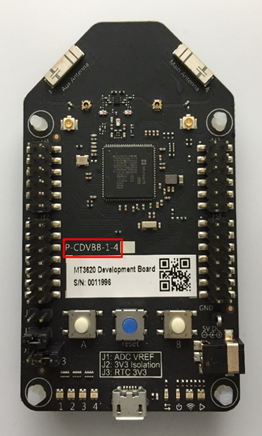 |
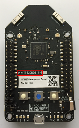 |
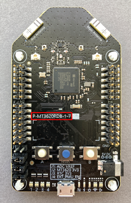 |
RDB design files
The RDB design files—schematics, layout, and bill of materials—are available for reference in the Azure Sphere Hardware Designs Git repository. The RDB was developed using Altium Designer. The design files therefore include Altium schematic files (extension: .SchDoc), an Altium layout file (extension: .PcbDoc), and an Altium project (extension: .PrjPcb). To assist those who do not use or have access to Altium Designer, PDFs of the design files and Gerber files are also included.
Purpose of the board
The RDB was designed to facilitate MT3620 connectivity, debugging, and expansion.
Connectivity features. The RDB includes the key elements needed to integrate MT3620 into an electronic device: the MT3620 itself, at least one Wi-Fi antenna, and essential external components including radio frequency (RF) matching, voltage regulators, and signal conditioning. In addition, programmable buttons and LEDs aid customers in testing and debugging their applications. The MT3620 development board user guide describes the buttons and LEDs, the Wi-Fi antennas, and the voltage regulators. To ensure compatibility with the Microsoft samples, any development board should support these features.
Debugging features. The RDB exposes the MT3620's two management UARTs and two control signals (reset and recovery) over USB in a way that enables the Azure Sphere PC software tools to recognize and interact with them. This USB interface thereby provides functionality for transferring an application to the board, loading a new operating system image, and debugging. The MCU Programming and Debugging Interface describes how the RDB implements these features and provides additional guidance for those who are designing boards that incorporate the MT3620.
Expansion features. The RDB includes multiple headers to allow additional hardware to be connected, either with jumper wires or with a custom-made shield. In this way it is possible to interface with a bus or connect to sensors, displays, and so forth. The MT3620 development board user guide includes details about the headers and programmable I/O (PIO) features.