Note
Access to this page requires authorization. You can try signing in or changing directories.
Access to this page requires authorization. You can try changing directories.
This topic covers access permission to the TOR switches, IP address assignments and other networking deployment tasks.
Plan configuration deployment
The next sections cover permissions and IP address assignments.
Physical switch access control list
To protect the Azure Stack solution, we have implemented access control lists (ACLs) on the TOR switches. This section describes how this security is implemented. The following table shows the sources and destinations of every network inside the Azure Stack solution:
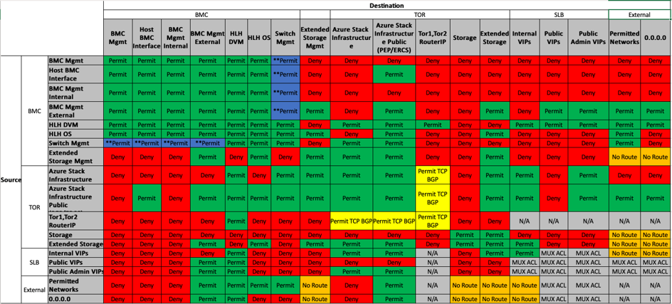
The following table correlates the ACL references with the Azure Stack networks.
| Network | Description |
|---|---|
| BMC Mgmt Internal | Traffic is limited to internal only. |
| BMC Mgmt External | ACL permit access to beyond the border device. |
| Extended Storage Mgmt | Dedicated management interfaces for the extended storage system |
| Switch Mgmt | Dedicated Switch management interfaces. |
| "Azure Stack Infrastructure" | Azure Stack Infrastructure services and VM's, restricted network |
| Azure Stack Infrastructure Public (PEP/ERCS) | Azure Stack Protected Endpoint, Emergency Recovery Console Server. Customer can open ACL to permit traffic to their datacenter management network. |
| Tor1,Tor2 RouterIP | Loopback interface of the switch used for BGP peering between the SLB and Switch/Router. The customer has the discretion to firewall off these IPs at the border. |
| Storage | Private IPs not routed outside of the Region |
| Internal VIPs | Private IPs not routed outside of the Region |
| Public VIPs | Tenant network address space managed by the network controller. |
| Public Admin VIPs | Small subset of addresses in the Tenant pool that are required to talk to Internal-VIPs and Azure Stack Infrastructure |
| Permitted Networks | Customer defined network. |
| 0.0.0.0 | From the perspective of Azure Stack 0.0.0.0 is the border device. |
| Permit | Permit traffic is enabled but SSH access is blocked by default. |
| No Route | Routes are not propagated outside of the Azure Stack environment. |
| MUX ACL | Azure Stack MUX ACLs are utilized. |
| N/A | Not a part of a VLAN ACL. |
IP address assignments
In the Deployment Worksheet, you are asked to provide the following network addresses to support the Azure Stack deployment process. The deployment team uses the Deployment Worksheet tool to break out the IP networks into all the smaller networks required by the system.
In this example, we fill the Network Settings tab of the Deployment Worksheet with the following values:
- BMC Network: 10.193.132.0 /27
- Private Network Storage Network & Internal VIPs: 11.11.128.0 /20
- Infrastructure Network: 12.193.130.0 /24
- Public Virtual IP (VIP) Network: 13.200.132.0 /24
- Switch Infrastructure Network: 10.193.132.128 /26
When you run the Generate function of the Deployment Worksheet tool, it creates two new tabs on the spreadsheet. The first tab is the Subnet Summary and it shows how the supernets were split to create all the networks required by the system. In our example below there is only a subset of the columns found on this tab. The actual result has more details of each network listed:
| Rack | Subnet type | Name | IPv4 Subnet | IPv4 addresses |
|---|---|---|---|---|
| Border | P2P Link | P2P_Border/Border1_To_Rack1/TOR1 | 10.193.132.128/30 | 4 |
| Border | P2P Link | P2P_Border/Border1_To_Rack1/TOR2 | 10.193.132.132/30 | 4 |
| Border | P2P Link | P2P_Border/Border2_To_Rack1/TOR1 | 10.193.132.136/30 | 4 |
| Border | P2P Link | P2P_Border/Border2_To_Rack1/TOR2 | 10.193.132.140/30 | 4 |
| Border | P2P Link | P2P_Rack1/TOR1_To_Rack1/BMC | 10.193.132.144/30 | 4 |
| Border | P2P Link | P2P_Rack1/TOR2_To_Rack1/BMC | 10.193.132.148/30 | 4 |
| Rack1 | Loopback | Loopback0_Rack1_TOR1 | 10.193.132.152/32 | 1 |
| Rack1 | Loopback | Loopback0_Rack1_TOR2 | 10.193.132.153/32 | 1 |
| Rack1 | Loopback | Loopback0_Rack1_BMC | 10.193.132.154/32 | 1 |
| Rack1 | P2P Link | P2P_Rack1/TOR1-ibgp-1_To_Rack1/TOR2-ibgp-1 | 10.193.132.156/30 | 4 |
| Rack1 | P2P Link | P2P_Rack1/TOR1-ibgp-2_To_Rack1/TOR2-ibgp-2 | 10.193.132.160/30 | 4 |
| Rack1 | VLAN | BMCMgmt | 10.193.132.0/27 | 32 |
| Rack1 | VLAN | SwitchMgmt | 10.193.132.168/29 | 8 |
| Rack1 | VLAN | CL01-RG01-SU01-Storage | 11.11.128.0/25 | 128 |
| Rack1 | VLAN | CL01-RG01-SU01-Infra | 12.193.130.0/24 | 256 |
| Rack1 | Other | CL01-RG01-SU01-VIPS | 13.200.132.0/24 | 256 |
| Rack1 | Other | CL01-RG01-SU01-InternalVIPS | 11.11.128.128/25 | 128 |
The second tab is IP Address Usage and it shows how the IPs are consumed:
BMC network
The supernet for the BMC network requires a /26 network at a minimum. The gateway uses the first IP in the network followed by the BMC devices in the rack. The hardware lifecycle host has multiple addresses assigned on this network and can be used to deploy, monitor, and support the rack. These IPs are distributed into 3 groups: DVM, InternalAccessible and ExternalAccessible.
- Rack: Rack1
- Name: BMCMgmt
| Assigned To | IPv4 address |
|---|---|
| Network | 10.193.132.0 |
| Gateway | 10.193.132.1 |
| HLH-BMC | 10.193.132.2 |
| AzS-Node01 | 10.193.132.3 |
| AzS-Node02 | 10.193.132.4 |
| AzS-Node03 | 10.193.132.5 |
| AzS-Node04 | 10.193.132.6 |
| ExternalAccessible-1 | 10.193.132.19 |
| ExternalAccessible-2 | 10.193.132.20 |
| ExternalAccessible-3 | 10.193.132.21 |
| ExternalAccessible-4 | 10.193.132.22 |
| ExternalAccessible-5 | 10.193.132.23 |
| InternalAccessible-1 | 10.193.132.24 |
| InternalAccessible-2 | 10.193.132.25 |
| InternalAccessible-3 | 10.193.132.26 |
| InternalAccessible-4 | 10.193.132.27 |
| InternalAccessible-5 | 10.193.132.28 |
| CL01-RG01-SU01-DVM00 | 10.193.132.29 |
| HLH-OS | 10.193.132.30 |
| Broadcast | 10.193.132.31 |
Storage network
The Storage network is a private network and isn't intended to be routed beyond the rack. It's the first half of the Private Network supernet and it's used by the switch distributed as shown on the table below. The gateway is the first IP in the subnet. The second half used for the Internal VIPs is a private pool of addresses that is managed by Azure Stack SLB, is not shown on the IP Address Usage tab. These networks support Azure Stack and there are ACLs on the TOR switches that prevent these networks from been advertised and/or accessed outside the solution.
- Rack: Rack1
- Name: CL01-RG01-SU01-Storage
| Assigned To | IPv4 address |
|---|---|
| Network | 11.11.128.0 |
| Gateway | 11.11.128.1 |
| TOR1 | 11.11.128.2 |
| TOR2 | 11.11.128.3 |
| Broadcast | 11.11.128.127 |
Azure Stack infrastructure network
The infrastructure network supernet requires a /24 network and this continues to be a /24 after the Deployment Worksheet tool runs. The gateway is the first IP in the subnet.
- Rack: Rack1
- Name: CL01-RG01-SU01-Infra
| Assigned To | IPv4 address |
|---|---|
| Network | 12.193.130.0 |
| Gateway | 12.193.130.1 |
| TOR1 | 12.193.130.2 |
| TOR2 | 12.193.130.3 |
| Broadcast | 12.193.130.255 |
Switch infrastructure network
The infrastructure network is broken into multiple networks used by the physical switch infrastructure. This is different from the Azure Stack Infrastructure which only supports the Azure Stack software. The Switch Infra Network supports only the physical switch infrastructure. The networks that are supported by infra are:
| Name | IPv4 Subnet |
|---|---|
| P2P_Border/Border1_To_Rack1/TOR1 | 10.193.132.128/30 |
| P2P_Border/Border1_To_Rack1/TOR2 | 10.193.132.132/30 |
| P2P_Border/Border2_To_Rack1/TOR1 | 10.193.132.136/30 |
| P2P_Border/Border2_To_Rack1/TOR2 | 10.193.132.140/30 |
| P2P_Rack1/TOR1_To_Rack1/BMC | 10.193.132.144/30 |
| P2P_Rack1/TOR2_To_Rack1/BMC | 10.193.132.148/30 |
| Loopback0_Rack1_TOR1 | 10.193.132.152/32 |
| Loopback0_Rack1_TOR2 | 10.193.132.153/32 |
| Loopback0_Rack1_BMC | 10.193.132.154/32 |
| P2P_Rack1/TOR1-ibgp-1_To_Rack1/TOR2-ibgp-1 | 10.193.132.156/30 |
| P2P_Rack1/TOR1-ibgp-2_To_Rack1/TOR2-ibgp-2 | 10.193.132.160/30 |
| SwitchMgmt | 10.193.132.168/29 |
- Point-to-point (P2P): These networks allow connectivity between all switches. The subnet size is a /30 network for each P2P. The lowest IP is always assigned to the upstream (North) device on the stack.
- Loopback: These addresses are /32 networks that are assigned to each switch used in the rack. The border devices are not assigned a loopback since they aren't expected to be part of the Azure Stack solution.
- Switch Mgmt or Switch Management: This /29 network supports the dedicated management interfaces of the switches in the rack. The IPs are assigned as follows; this table can also be found on the IP Address Usage tab of the Deployment Worksheet:
- Rack: Rack1
- Name: SwitchMgmt
| Assigned To | IPv4 Address |
|---|---|
| Network | 10.193.132.168 |
| Gateway | 10.193.132.169 |
| TOR1 | 10.193.132.170 |
| TOR2 | 10.193.132.171 |
| Broadcast | 10.193.132.175 |
Prepare environment
The hardware lifecycle host image does contain the required Linux container that is used to generate the physical network switch configuration.
The latest partner deployment toolkit does include the latest container image. The container image on the hardware lifecycle host can be replaced when it is necessary to generate an updated switch configuration.
These steps update the container image:
- Download the container image
- Replace the container image at the following location
Generate configuration
This section shows the steps to generate the JSON files and the Network Switch Configuration files.
Open the Deployment Worksheet
Fill all the required fields on all tabs
Invoke the Generate function on the Deployment Worksheet. Two extra tabs are created, displaying the generated IP subnets and assignments.
Review the data and once confirmed, invoke the "Export" function. You are prompted to provide a folder in which to save the JSON files.
Execute the container using the Invoke-SwitchConfigGenerator.ps1. This script requires an elevated PowerShell console to execute and requires the following parameters to execute.
- ContainerName – Name of the container that generates the switch configs.
- ConfigurationData – Path to the ConfigurationData.json file exported from the Deployment Worksheet.
- OutputDirectory – Path to the output directory.
- Offline – Signals that the script runs in offline mode.
Invoke-SwitchConfigGenerate.ps1 -ContainerName generalonrampacr.azurecr.io/master -ConfigurationData .\ConfigurationData.json -OutputDirectory c:\temp -Offline
When the script completes, it produces a .zip file with the prefix used in the worksheet.
Seconds : 2
Section : Validation
Step    : WindowsRequirement
Status  : True
Detail  : @{CurrentImage=10.0.18363.0}


Seconds : 2
Section : Validation
Step    : DockerService
Status  : True
Detail  : @{Status=Running}


Seconds : 9
Section : Validation
Step    : DockerSetup
Status  : True
Detail  : @{CPU=4; Memory=4139085824; OS=Docker Desktop; OSType=linux}


Seconds : 9
Section : Validation
Step    : DockerImage
Status  : True
Detail  : @{Container=generalonrampacr.azurecr.io/master:1.1910.78.1}


Seconds : 10
Section : Run
Step    : Container
Status  : True
Detail  : @{ID=2a20ba622ef9f58f9bcd069c3b9af7ec076bae36f12c5653f9469b988c01706c; ExternalPort=32768}


Seconds : 38
Section : Generate
Step    : Config
Status  : True
Detail  : @{OutputFile=c:\temp\N22R19.zip}


Seconds : 38
Section : Exit
Step    : StopContainer
Status  : True
Detail  : @{ID=2a20ba622ef9f58f9bcd069c3b9af7ec076bae36f12c5653f9469b988c01706c}
Custom configuration
You can modify a few environmental settings for your Azure Stack switch configuration. You can identify which of the settings you can change in the template. This article explains each of those customizable settings, and how the changes can affect your Azure Stack. These settings include password update, syslog server, SNMP monitoring, authentication, and the access control list.
During deployment of the Azure Stack solution, the original equipment manufacturer (OEM) creates and applies the switch configuration for both TORs and BMC. The OEM uses the Azure Stack automation tool to validate that the required configurations are properly set on these devices. The configuration is based the information in your Azure Stack Deployment Worksheet.
Note
Don't alter the configuration without consent from either the OEM or the Microsoft Azure Stack engineering team. A change to the network device configuration can significantly impact the operation or troubleshooting of network issues in your Azure Stack instance. For more information about these functions on your network device, how to make these changes, please contact your OEM hardware provider or Microsoft support. Your OEM has the configuration file created by the automation tool based on your Azure Stack deployment worksheet.
However, there are some values that can be added, removed, or changed on the configuration of the network switches.
Password update
The operator may update the password for any user on the network switches at any time. There isn't a requirement to change any information on the Azure Stack system, or to use the steps for Rotate secrets in Azure Stack.
Syslog server
Operators can redirect the switch logs to a syslog server on their datacenter. Use this configuration to ensure that the logs from a particular point in time can be used for troubleshooting. By default, the logs are stored on the switches; their capacity for storing logs is limited. Check the Access control list updates section for an overview of how to configure the permissions for switch management access.
SNMP monitoring
The operator can configure simple network management protocol (SNMP) v2 or v3 to monitor the network devices and send traps to a network monitoring application on the datacenter. For security reasons, use SNMPv3 since it is more secure than v2. Consult your OEM hardware provider for the MIBs and configuration required. Check the Access control list updates section for an overview of how to configure the permissions for switch management access.
Authentication
The operator can configure either RADIUS or TACACS to manage authentication on the network devices. Consult your OEM hardware provider for supported methods and configuration required. Check the Access control list updates section for an overview of how to configure the permissions for Switch Management access.
Access control list updates
The operator can change some access control list (ACL)s to allow access to network device management interfaces and the hardware lifecycle host (HLH) from a trusted datacenter network range. The operator can pick which component is reachable, and from where. With the access control list, The operator can allow their management jumpbox VMs within a specific network range to access the switch management interface, and the HLH OS, and the HLH BMC.
For more information, see Physical switch access control list.
TACACS, RADIUS and Syslog
The Azure Stack solution is not shipped with a TACACS or RADIUS solution for access control of devices like the switches and routers, nor a Syslog solution to capture switch logs, but all these devices support those services. To help integrate with an existing TACACS, RADIUS and/or Syslog server on your environment, we provide an extra file with the Network Switch Configuration which allows the engineer onsite to customize the switch to the customer's needs.