Note
Access to this page requires authorization. You can try signing in or changing directories.
Access to this page requires authorization. You can try changing directories.
This section is an overview of the server components.
Chassis front view
The following figure shows the 2U server.
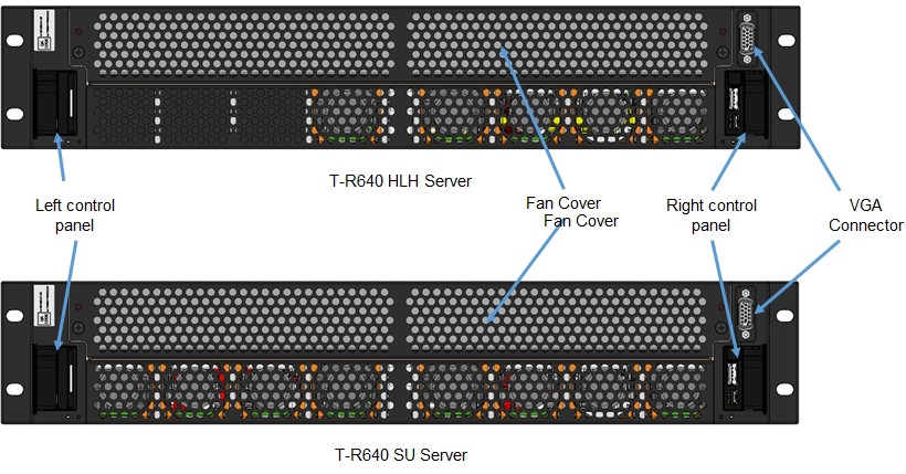
The following table describes the front panel features.
| Ports, panels, and slots | Description |
|---|---|
| Left control panel | Contains the system health and system ID, status LED, and the iDRAC Quick Sync 2 (wireless) indicator. Note: The iDRAC Quick Sync 2 indicator is available only on certain configurations. Status LED: Enables you to identify any failed hardware components. There are up to five status LEDs and an overall system health LED (chassis health and system ID) bar. Quick Sync 2 (wireless): Indicates a Quick Sync enabled system. The Quick Sync feature is optional. This feature allows management of the system by using mobile devices. This feature aggregates hardware or firmware inventory and various system-level diagnostic and error information that can be used in troubleshooting the system. |
| VGA port | Enables you to connect a display device to the system. |
| Right control panel | Contains the power button, USB port, iDRAC Direct micro port, and the iDRAC Direct status LED. |
Chassis back view
The following figure shows the back chassis components.
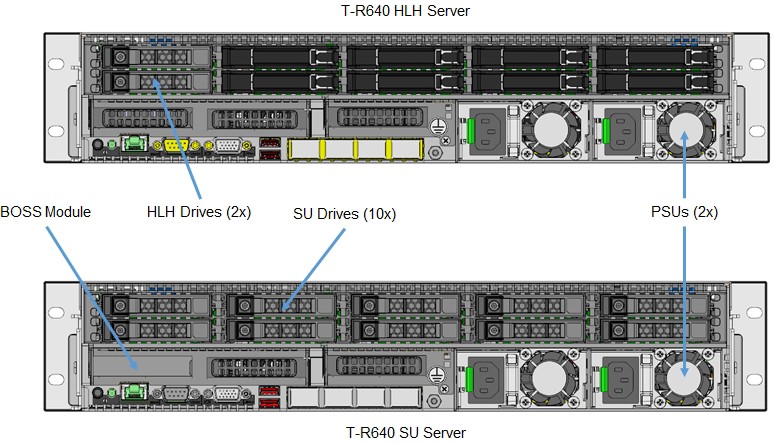
The following table describes the features on the back panel.
| Ports, panels and slots | Icon | Description |
|---|---|---|
| Hard drives | N/A | OS and data storage for the HLH and SU server nodes. |
| BOSS module | N/A | Boot Optimized Storage Solution (BOSS), used to install the operating system or hypervisor. |
| Power supply units (2) | N/A | These supply power to the server and are provided in tandem for redundancy. |
| USB 3.0 ports | 
|
The USB ports are 9-pin and 3.0-compliant. These ports enable you to connect USB devices to the system. |
| VGA port | 
|
Enables you to connect a display device to the system. |
| Serial port | 
|
Enables you to connect a serial device to the system. |
| iDRAC9 Enterprise port | 
|
Enables you to remotely access iDRAC. |
| CMA power port | N/A | The Cable Management Arm (CMA) power port enables you to connect the Status Indicator Cable to the CMA. |
| System identification button | 
|
The System Identification (ID) button is available on the server's front and back. Pressing the button causes the System health\System ID indicator to blink. You can also use the system ID button to reset the iDRAC and to access the BIOS using the step-through mode. |
Right control panel
The following figure shows the right control panel.
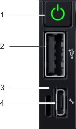
The following table describes the controls and indicators on the right panel.
| Item | Indicator or button | Icon | Description |
|---|---|---|---|
| 1 | Power button | 
|
Indicates if the system is turned on or off. Press the power button to manually turn on or off the system. Note: Press the power button to gracefully shut down an ACPI- compliant operating system. |
| 2 | USB port | 
|
The USB port is 4-pin, 2.0-compliant. This port enables you to connect USB devices to the system. |
| 3 | iDRAC Direct LED | N/A | The iDRAC Direct LED indicator lights up to indicate that the iDRAC Direct port is actively connected to a device. |
| 4 | iDRAC Direct port |
|
The iDRAC Direct port is micro USB 2.0-compliant. This port enables you to access the iDRAC Direct features. |
Inside the server
The following figures shows the internal server components.
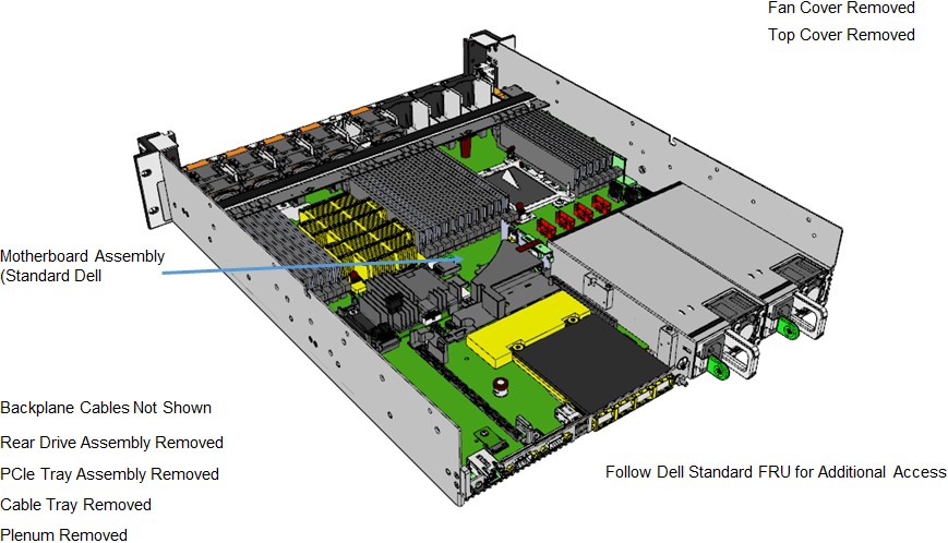
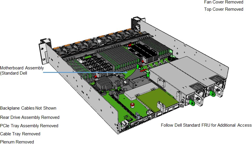
Motherboard
The following figure shows the motherboard layout.
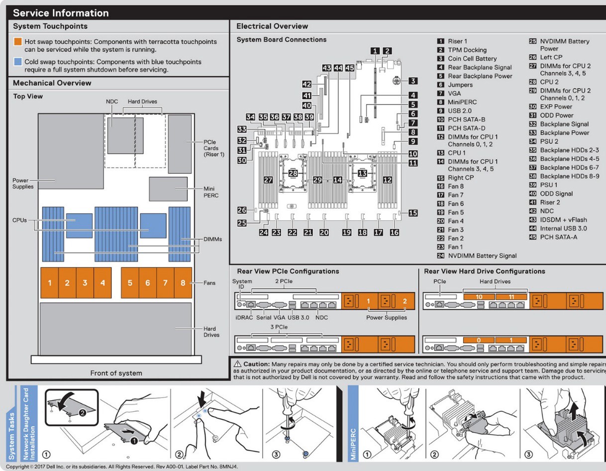
Memory
The following figure shows the memory information.
