Blue-green deployment of AKS clusters
This article provides guidance on implementing a blue-green deployment strategy to test a new version of an Azure Kubernetes Service (AKS) cluster while continuing to run the current version. Once the new version is validated, a routing change switches user traffic to it. Deploying in this way increases availability when making changes, including upgrades, to AKS clusters. This article describes the design and implementation of a blue-green deployment of AKS that uses Azure managed services and native Kubernetes features.
Architecture
This section describes architectures for blue-green deployment of AKS clusters. There are two cases:
- The applications and APIs are public-facing.
- The applications and APIs are private-facing.
There's also a hybrid case, not discussed here, in which there's a mix of public-facing and private-facing applications and APIs in the cluster.
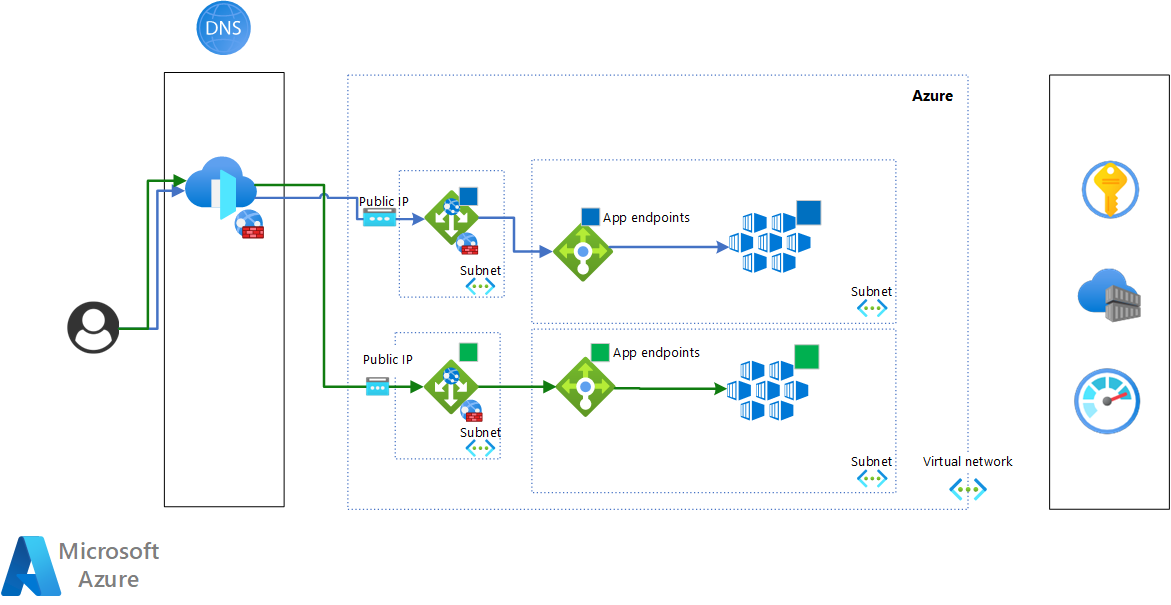
The following diagram shows the architecture for the public-facing case:
Download a Visio file of this architecture.
Azure Front Door and Azure DNS provide the routing mechanism that switches traffic between the blue and green clusters. For more information, see Blue-green deployment with Azure Front Door. By using Azure Front Door, it's possible to implement a full switch or a more controlled switch that's based on weights. This technique is the most reliable and efficient in an Azure environment. If you want to use your own DNS and load balancer, you need to be sure that they're configured to provide a safe and reliable switch.
Azure Application Gateway provides the front ends, which are dedicated to the public endpoints.
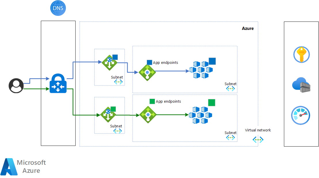
This diagram is for the private-facing case:
Download a Visio file of this architecture.
For this case, a single Azure DNS instance implements the switching of traffic between the blue and green clusters. This is done by using A and CNAME records. For details, see section T3: Switch traffic to the green cluster.
Application Gateway provides the front ends, which are dedicated to the private endpoints.
Workflow
In a blue-green deployment there are five stages to updating the current version of the cluster to the new version. In our description, the blue cluster is the current version, and the green cluster is the new one.
The stages are:
- T0: The blue cluster is on.
- T1: Deploy the green cluster.
- T2: Sync the Kubernetes state between the blue and green clusters.
- T3: Switch traffic to the green cluster.
- T4: Destroy the blue cluster.
Once the new version is live, it becomes the blue cluster for whatever change or update comes next.
The blue and green clusters run at the same time, but only for a limited period of time, which optimizes costs and operational efforts.
Transition triggers
The triggers to transition from stage to stage can be automated. Until that's achieved, some or all of them are manual. The triggers are related to:
- Specific workload metrics, service-level objectives (SLOs), and service-level agreements (SLAs): These are used mainly in the T3 stage to validate the overall state of the AKS cluster before switching the traffic.
- Azure platform metrics: These are used to evaluate the status and health of the workloads and the AKS cluster. They're used in all of the transitions.
Network discoverability of the clusters
You can provide network discoverability for the clusters in the following ways:
Have DNS records that point to the clusters. For example:
aks-blue.contoso.compoints to the private or public IP of the blue cluster.aks-green.contoso.compoints to the private or public IP of the green cluster.
Then you can use these host names directly or in the backend pool configuration of the application gateway that's in front of each cluster.
Have DNS records that point to the application gateways. For example:
aks-blue.contoso.compoints to the private or public IP of the application gateway, which has as backend pool the private or public IP of the blue cluster.aks-green.contoso.compoints to the private or public IP of the application gateway, which has as backend pool the private or public IP of the green cluster.
T0: The blue cluster is on
The initial stage, T0, is that the blue cluster is live. This stage prepares the new version of the cluster for deployment.
The trigger condition for the T1 stage is the release of a new version of the cluster, the green cluster.
T1: Deploy the green cluster
This stage begins the deployment of the new green cluster. The blue cluster remains on, and the live traffic is still routed to it.
The trigger to move into the T2 stage is the validation of the green AKS cluster at the platform level. The validation uses Azure Monitor metrics and CLI commands to check the health of the deployment. For more information, see Monitoring Azure Kubernetes Service (AKS) with Monitor and Monitoring AKS data reference.
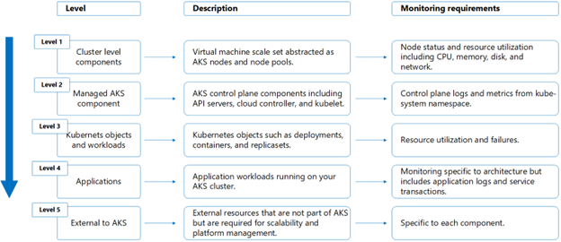
The AKS monitoring can be split into different levels, as shown in the following diagram:
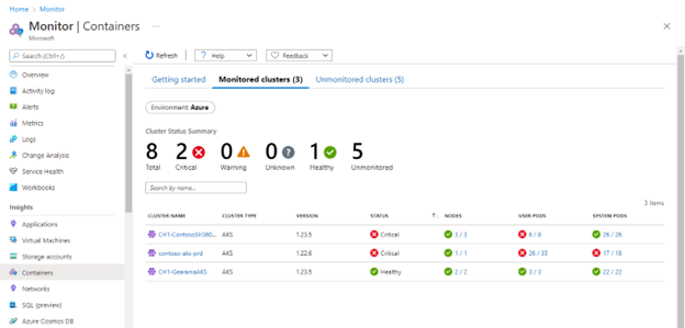
The health of the cluster is evaluated at levels 1 and 2, and at some of level 3. For level 1, you can use the native multi-cluster view from Monitor to validate the health, as shown here:
At level 2, make sure that the Kubernetes API server and Kubelet work properly. You can use the Kubelet workbook in Monitor, specifically, the two grids of the workbook that show key operating statistics of the nodes:
- The overview by node grid summarizes total operation, total errors, and successful operations by percent and trend for each node.
- The overview by operation type grid provides, for each type of operation, the number of operations, errors, and successful operations by percent and trend.
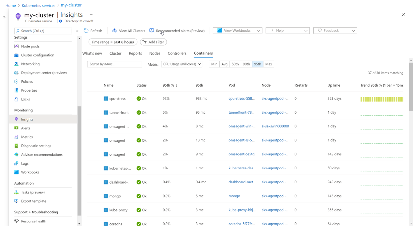
Level 3 is dedicated to the Kubernetes objects and applications that are deployed by default in AKS, like omsagent, kube-proxy and so on. For this check, you can use the Insights view of Monitor to check the status of the AKS deployments:
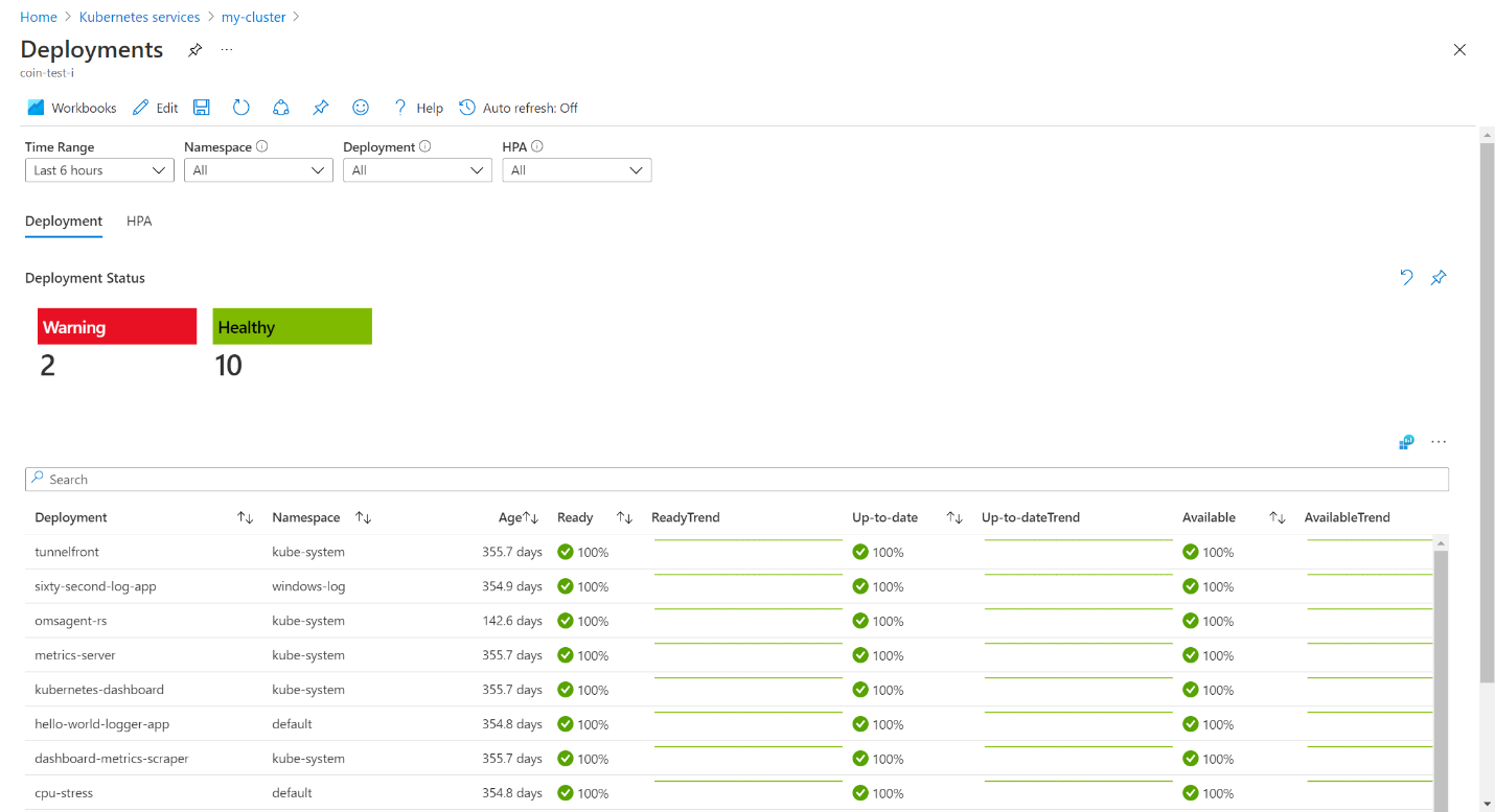
As an alternative, you can use the dedicated workbook that's documented in Deployment & HPA metrics with Container insights. Here's an example:
After validation succeeds, you can transition to the T2 stage.
T2: Sync the Kubernetes state between the blue and green clusters
At this stage, applications, operators, and Kubernetes resources aren't yet deployed in the green cluster, or at least not all of them are applicable and deployed when the AKS cluster is provisioned. The ultimate goal of this stage is that, at the end of the sync, the green cluster is backward compatible with the blue one. If so, it's possible to validate the status of the new cluster before switching traffic to the green cluster.
There are various ways to sync the Kubernetes state between clusters:
- Redeployment via continuous integration and continuous delivery (CI/CD). Usually it's enough to use the same CI/CD pipelines that are used for the normal deployment of the apps. Common tools for doing this are: GitHub Actions, Azure DevOps, and Jenkins.
- GitOps, with solutions that are promoted on the Cloud Native Computing Foundation (CNCF) website, like Flux and ArgoCD.
- A customized solution that stores the Kubernetes configurations and resources in a datastore. Usually, these solutions are based on Kubernetes manifest generators that start from metadata definitions and then store the generated Kubernetes manifests into a datastore like Azure Cosmos DB. These are usually custom solutions that are based on the application description framework that's in use.
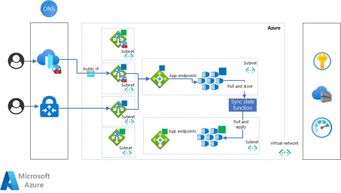
The following diagram shows the process of syncing the Kubernetes state:
Usually, during the sync, the deployment of new versions of applications isn't permitted in the live cluster. This period of time starts with the sync and finishes when the switch to the green cluster completes. The way to disable deployments in Kubernetes can vary. Two possible solutions are:
Disable the deployment pipelines.
Disable the Kubernetes service account that executes deployments.
It's possible to automate the disabling of the service account by using the Open Policy Agent (OPA). It isn't yet possible to use AKS native features for this because they're still in preview.
The sync period can be avoided by using advanced mechanisms that manage the Kubernetes state in multiple clusters.
When the sync is completed, validation of the cluster and applications is required. This includes:
- A check of the monitoring and logging platforms to validate the health of the cluster. You can consider doing what you do in the T1: Deploy the green cluster stage.
- Functional testing of the application based on the toolchain that's currently in use.
We recommend that you also execute a load test session to compare the performance of the green cluster applications against a performance baseline. You can use your preferred tool or Azure Load Testing.
Usually, the green cluster is exposed on the application gateway or external load balancer with an internal URL that isn't visible to external users.
When the new cluster is validated, you can proceed to the next stage to switch traffic to the new cluster.
T3: Switch traffic to the green cluster
After the sync is complete and the green cluster is validated at platform and application levels, it's ready to be promoted to be the primary cluster and to start receiving the live traffic. The switch is performed at the networking level. Often the workloads are stateless. However, if the workloads are stateful, an additional solution must be implemented to maintain the state and caching during the switch.
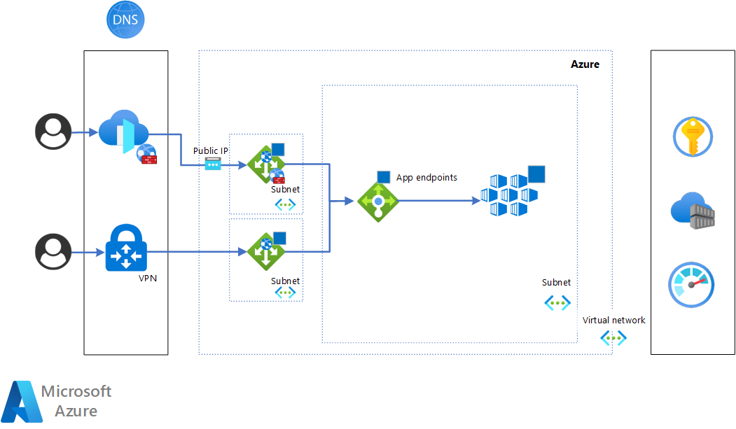
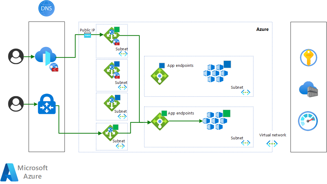
Here's a diagram that shows the target state after the switch is applied:
The techniques that are described in this article implement full switches: 100% of the traffic is routed to the new cluster. This is because the routing is applied at DNS level with an A or CNAME record assignment that's updated to point to the green cluster, and there's an application gateway for each cluster.
Here's an example of configuration for switching private-facing endpoints. The proposed solution uses A records to make the switch. From a DNS and IP mapping perspective, the situation is as follows before the switch:
Arecordaks.priv.contoso.compoints to the private IP of the blue application gateway.Arecordaks-blue.priv.contoso.compoints to the private IP of the blue application gateway.Arecordaks-green.priv.contoso.compoints to the private IP of the green application gateway.
The switch reconfigures to the following:
Arecordaks.priv.contoso.compoints to the private IP of the green application gateway.Arecordaks-blue.priv.contoso.compoints to the private IP of the blue application gateway.Arecordaks-green.priv.contoso.compoints to the private IP of the green application gateway.
The users of the clusters will see the switch after the time to live (TTL) and DNS propagation of the records.
For public-facing endpoints, the recommended approach uses Azure Front Door and Azure DNS. Here's the configuration before the switch:
CNAMErecordofficial-aks.contoso.compoints to a record of the autogenerated Azure Front Door domain. For more information, see Tutorial: Add a custom domain to your Front Door.Arecordaks.contoso.compoints to the public IP of the blue application gateway.- The Azure Front Door origin configuration points to the
aks.contoso.comhost name. For more information about configuring the backend pools, see Origins and origin groups in Azure Front Door.Arecordaks-blue.contoso.compoints to the public IP of the blue application gateway.Arecordaks-green.contoso.compoints to the public IP of the green application gateway.
The switch reconfigures to the following:
CNAMErecordofficial-aks.contoso.compoints to a record of the autogenerated Azure Front Door domain.Arecordaks.contoso.compoints to public IP of the green application gateway.- The Azure Front Door origin configuration points to the
aks.contoso.comhost name.Arecordaks-blue.contoso.compoints to public IP of the blue application gateway.Arecordaks-green.contoso.compoints to public IP of the green application gateway.
Alternative switching techniques, like partial switches for canary releases, are possible with additional Azure services like Azure Front Door or Traffic Manager. For an implementation of a blue-green traffic switch at the Azure Front Door level, see Blue-green deployment with Azure Front Door.
As described in the example, from a networking perspective this technique is based on the definition of four host names:
- Official public facing host name: The official public host name that's used by end users and consumers.
- Cluster host name: The official host name that's used by the consumers of the workloads that are hosted in the clusters.
- Blue cluster host name: The dedicated host name for the blue cluster.
- Green cluster host name: The dedicated host name for the green cluster.
The cluster host name is the one that's configured at the application gateway level to manage the ingress traffic. The host name is also part of the AKS ingress configuration in order to manage Transport Layer Security (TLS) properly. This host is used only for live transactions and requests.
If Azure Front Door is also part of the deployment, it isn't affected by the switch, because it manages only the official cluster host name. It provides the proper abstraction for the application users. They aren't affected by the switch, because the DNS CNAME record always points to Azure Front Door.
The blue and green cluster host names are mainly used to test and validate the clusters. For these purposes, the host names are exposed at the application gateway level with dedicated endpoints, and also at the AKS ingress controller level to manage TLS properly.
At this stage, validation is based on the infrastructure and app monitoring metrics, and on official SLO and SLA, when available. If validation succeeds, transition to the final stage to destroy the blue cluster.
T4: Destroy the blue cluster
Switching the traffic successfully brings us to the final stage, in which there's still validation and monitoring happening to ensure that the green cluster works as expected with live traffic. The validation and monitoring cover both platform and application level.
After this validation is completed, the blue cluster can be destroyed. The destruction is a step that's strongly recommended in order to reduce costs and make proper use of the elasticity that Azure provides, particularly AKS.
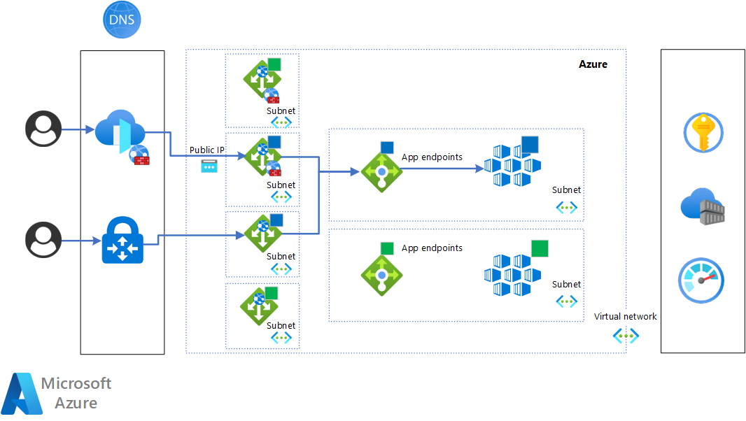
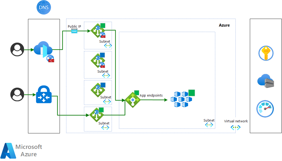
Here's the situation after the blue cluster is destroyed:
Components
- Application Gateway is a web traffic (OSI layer 7) load balancer that enables you to manage traffic to your web applications. In this solution it is used as gateway for HTTP traffic to access the AKS clusters.
- Azure Kubernetes Service (AKS) is a managed Kubernetes service that you can use to deploy and manage containerized applications. This application platform is the main component of this pattern.
- Azure Container Registry is a managed service used to store and manage container images and related artifacts. In this solution is used to store and distribute container images and artifacts, such as Helm charts, in the AKS clusters.
- Azure Monitor is a monitoring solution for collecting, analyzing, and responding to monitoring data from your cloud and on-premises environments. It provides the core monitoring features required to execute the blue green deployment. It is used in this architecture because of its integration with AKS and its ability to provide logging, monitoring, and alerting capabilities that can be used to manage the stage transitions.
- Azure Key Vault helps solve the following problems:Secrets Management, Key Management and Certificate Management; it is used to store and manage the secrets and certificates required at platform and application level for this solution.
- Azure Front Door is a global load balancer and application endpoint management system. It is used in this solution as the public endpoint for HTTP applications that are hosted on AKS. In this solution it has the critical responsibility to manage the traffic switch between the blue and green application gateways.
- Azure DNS is a hosting service for DNS domains that provides name resolution by using Microsoft Azure infrastructure. It manages the host names that are used in the solution for the blue and green clusters, and it plays an important role in the traffic switches, particularly for private endpoints.
Alternatives
- There are alternative techniques for implementing the traffic switches that can provide more control. For example, it's possible to do a partial switch by using traffic rules that are based on one or more of the following:
- Percentage of incoming traffic
- HTTP headers
- Cookies
- Another alternative that provides greater protection from problems caused by changes is to have ring-based deployments. Instead of just blue and green clusters, it's possible to have more clusters, called rings. Each ring is large enough for the number of users that have access to the new version of AKS. As for the blue-green deployment that's described here, the rings can be removed to have the proper cost optimization and control.
- Possible alternatives to Application Gateway are NGINX and HAProxy.
- A possible alternative to Container Registry is Harbor.
- In some circumstances it's possible to use different load balancing and DNS services to do the traffic switches, instead of Azure Front Door and Azure DNS.
- This solution is based on the standard ingress controller Kubernetes APIs. If your solution would benefit instead from the Gateway API, then use Application Gateway for Containers. It can help manage load balancing and handle ingress traffic management between Application Gateway and the pods. Application Gateway for Containers controls the settings of the application gateways.
Scenario details
The main benefits of the solution are:
- Minimized downtime during the deployment.
- Planned rollback strategy.
- Improved control and operations during the release and deployment of AKS changes and upgrades.
- Testing for the need to execute disaster recovery (DR) procedures.
The key principles and foundational aspects of blue-green deployment are discussed in these articles:
- What is infrastructure as code (IaC)?
- What is Mutable vs. Immutable Infrastructure?
- What is elastic computing or cloud elasticity?
- What is continuous delivery?
From the perspective of automation and CI/CD, the solution can be implemented in multiple ways. We suggest:
- Bicep or Terraform for IaC.
- Azure Pipelines or GitHub Actions for CI/CD.
Potential use cases
Blue-green deployment makes it possible to make changes to clusters without affecting the running applications and workloads. Examples of changes are:
- Operational changes
- Activating new AKS features
- Changes to shared resources in the clusters
- Updating the Kubernetes version
- Modifying Kubernetes resources and objects, like the ingress gateway, the service mesh, operators, network policies and so on
- Rolling back to the previous version of an AKS cluster that's still deployed, without affecting the workloads that are running in the cluster
Considerations
These considerations implement the pillars of the Azure Well-Architected Framework, which is a set of guiding tenets that can be used to improve the quality of a workload. For more information, see Microsoft Azure Well-Architected Framework.
- Blue-green deployment can be fully automated, like a zero-touch deployment. Usually, an initial implementation has manual triggers to activate the stages. Along the way and with the proper maturity and monitoring features, it's possible to automate the triggers. This means that there's automated testing and specific metrics, SLA, and SLO to automate the triggers.
- It's important to have dedicated host names for the blue and green clusters and also to have dedicated endpoint configurations on the gateways and load balancers that are in front of the clusters. This is critical to improving the reliability and validity of the deployment of the new cluster. This way, the validation of the deployment happens with the same architecture and configurations of a standard production cluster.
- Consider a situation in which the AKS clusters are shared resources for multiple applications that are managed by different business units. In such cases it's common that the AKS platform itself is managed by a dedicated team that's responsible for the overall operation and lifecycle of the clusters, and that there are endpoints in the clusters for admin and ops purposes. We suggest that these endpoints have a dedicated ingress controller in the AKS clusters for proper separation of concerns and for reliability.
- Blue-green deployment is useful for implementing and testing business continuity and disaster recovery (BC/DR) solutions for AKS and related workloads. In particular, it provides the fundamental structures for managing multiple clusters, including cases in which the clusters are spread among multiple regions.
- Success with blue-green deployment relies on applying all aspects of the implementation, like automation, monitoring, and validation, not only to the AKS platform, but also to the workloads and apps that are deployed on the platform. Doing this helps you get maximum benefit from blue-green deployment.
- In the proposed solution there are two Application Gateways per each scenario public and private, so in total four. This decision is to apply blue green deployment at the Azure Application Gateway level it to avoid downtime caused by misconfiguration of the gateways. The main drawback of this decision is the cost, since there are four Application Gateway instances. They run in parallel only in the period of time in which there are relevant changes to the Application Gateway configs, such as WAF policies or a scaling configuration. For further cost optimization you can opt for a single Application Gateway per each scenario, this means two Application Gateway in total. This will require you to move the blue/green logic to the application gateway, instead of Azure Front Door. So instead of Azure Front Door being imperatively controlled, Application Gateway is.
Reliability
Reliability ensures that your application can meet the commitments you make to your customers. For more information, see Overview of the reliability pillar.
- Blue-green deployment has a direct and positive effect on the availability of the AKS platform and workloads. In particular, it increases availability during the deployment of AKS platform changes. There's little downtime if user sessions are managed well.
- Blue-green deployment provides coverage for reliability during the deployment because, by default, there's the option to roll back to the previous version of the AKS cluster if something goes wrong in the new cluster version.
Cost optimization
Cost optimization is about looking at ways to reduce unnecessary expenses and to improve operational efficiencies. For more information, see Overview of the cost optimization pillar.
- Blue-green deployment is widely adopted in Azure due to the native elasticity provided by the cloud. This makes it possible to optimize costs in term of operations and resource consumption. Most of the savings result from removing the cluster that's no longer needed after successfully deploying a new version of the cluster.
- When a new version is deployed, it's typical to host both the blue and green clusters in the same subnet, to continue to have the same cost baseline. All the network connections and access to the resources and services are the same for the two clusters, and all the Azure services and resources remain the same.
Operational excellence
Operational excellence covers the operations processes that deploy an application and keep it running in production. For more information, see Overview of the operational excellence pillar.
- Blue-green deployment, properly implemented, provides automation, continuous delivery, and resilient deployment.
- One of the key aspects of continuous delivery is that it iteratively delivers increments of platform and workload changes. With blue-green deployment of AKS, you achieve continuous delivery at the platform level, in a controlled and safe way.
- Resiliency is fundamental to blue-green deployment, because it includes the option to roll back to the previous cluster.
- Blue-green deployment provides the proper level of automation to reduce the effort related to business continuity strategy.
- Monitoring the platform and the apps is crucial for a successful implementation. For the platform it's possible to use the native Azure monitoring capabilities. For the apps, monitoring needs to be designed and implemented.
Deploy this scenario
For an implemented example of a blue-green deployment described in this guide, see AKS in an application landing zone.
This reference implementation is based on Application Gateway and Application Gateway Ingress Controller (AGIC). Each cluster has its own application gateway and the traffic switch is done via DNS, in particular via CNAME configuration.
Important
For mission-critical workloads, it is important to combine blue/green deployments as outlined in this guide with deployment automation and continuous validation to achieve zero downtime deployments. More information and guidance is available in the Mission-critical design methodology.
Region considerations
You can deploy the blue and green clusters to separate regions or to the same region. The design and operational principles aren't affected by this choice. However, certain types of additional networking configurations can be affected, such as:
- A dedicated virtual network and subnet for AKS and the application gateway.
- Connection with backing services like Monitor, Container Registry, and Key Vault.
- Azure Front Door visibility of the application gateway.
There are prerequisites for deploying into the same region:
- The virtual networks and subnets must be sized to host two clusters.
- The Azure subscription must provide sufficient capacity for the two clusters.
Deployment of the ingress controller and external load balancers
There are different approaches to the deployment of the ingress controller and external load balancers:
- You can have a single ingress controller with a dedicated external load balancer, like the reference implementation of the architecture described in this guide. AGIC is a Kubernetes application that makes it possible to use the Application Gateway L7 load balancer to expose cloud software to the internet. In certain scenarios, there are admin endpoints in the AKS clusters in addition to the application endpoints. The admin endpoints are for doing operational tasks on the applications or for configuration tasks like updating configuration maps, secrets, network policies, and manifests.
- You can have a single external load balancer that serves multiple ingress controllers that are deployed on the same cluster or on multiple clusters. This approach isn't covered in the reference implementation. In this scenario we recommend that you have separate application gateways for public facing endpoints and for private ones.
- The resulting architecture that's proposed and depicted in this guide is based on a standard ingress controller that's deployed as part of the AKS cluster, like NGINX and Envoy based ones. In the reference implementation we use AGIC, which means that there's a direct connection between the application gateway and the AKS pods, but this doesn’t affect the overall blue-green architecture.
Contributors
This article is maintained by Microsoft. It was originally written by the following contributors.
Principal authors:
- Vincenzo Morra | SAO Incubation Architect
Other contributors:
- Oscar Pla Alvarez | Domain Solution Architect
To see non-public LinkedIn profiles, sign in to LinkedIn.
Next steps
- What is infrastructure as code (IaC)?
- Blue-green deployment (Martin Fowler)
- AKS documentation
- Monitor documentation
- AKS in an application landing zone with blue-green deployments
- Architecture pattern for mission-critical workloads on Azure
- Azure services for securing network connectivity
- Microsoft Cloud Adoption Framework for Azure
