Note
Access to this page requires authorization. You can try signing in or changing directories.
Access to this page requires authorization. You can try changing directories.
The hub and spoke topology is a common network architecture pattern in Azure. In this setup, the hub is a virtual network (VNet) that serves as a central point of connectivity to your on-premises network. The spokes are VNets that peer with the hub and can be used to isolate workloads. The hub can secure and route traffic between spokes using various methods.
For instance, you can use Azure Route Server with dynamic routing and network virtual appliances (NVAs) to route traffic between spokes, though this can be complex. A simpler method involves using Azure Firewall and static routes.
This article demonstrates how to use Azure Firewall with static user-defined routes (UDRs) to route traffic in a multi hub and spoke topology. The following diagram illustrates the topology:

Baseline architecture
Azure Firewall not only secures and inspects network traffic but also routes traffic between VNets. It automatically creates system routes to local spokes, the hub, and on-premises prefixes learned by its local Virtual Network Gateway. Placing an NVA on the hub and querying the effective routes would show a route table similar to that within Azure Firewall.
In this static routing architecture, the shortest path to another hub is achieved using global VNet peering between hubs. Each hub knows about the other hubs, and each local firewall contains the route table of each directly connected hub. However, local hubs only know about their local spokes. These hubs can be in the same or different regions.
Routing on the firewall subnet
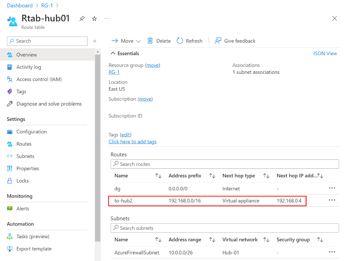
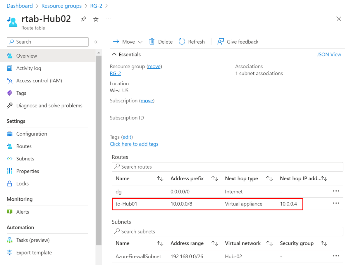
Each local firewall needs to know how to reach remote spokes, so you must create UDRs in the firewall subnets. Start by creating a default route, then add more specific routes to the other spokes. The following screenshots show the route tables for the two hub VNets:
Note
The address prefix in the hub virtual route table should encompass the address spaces of the two spoke virtual networks.
Hub-01 route table
Hub-02 route table
Routing on the spoke subnets
This topology allows traffic to move from one hub to another, reaching the next hop directly connected via global peering.
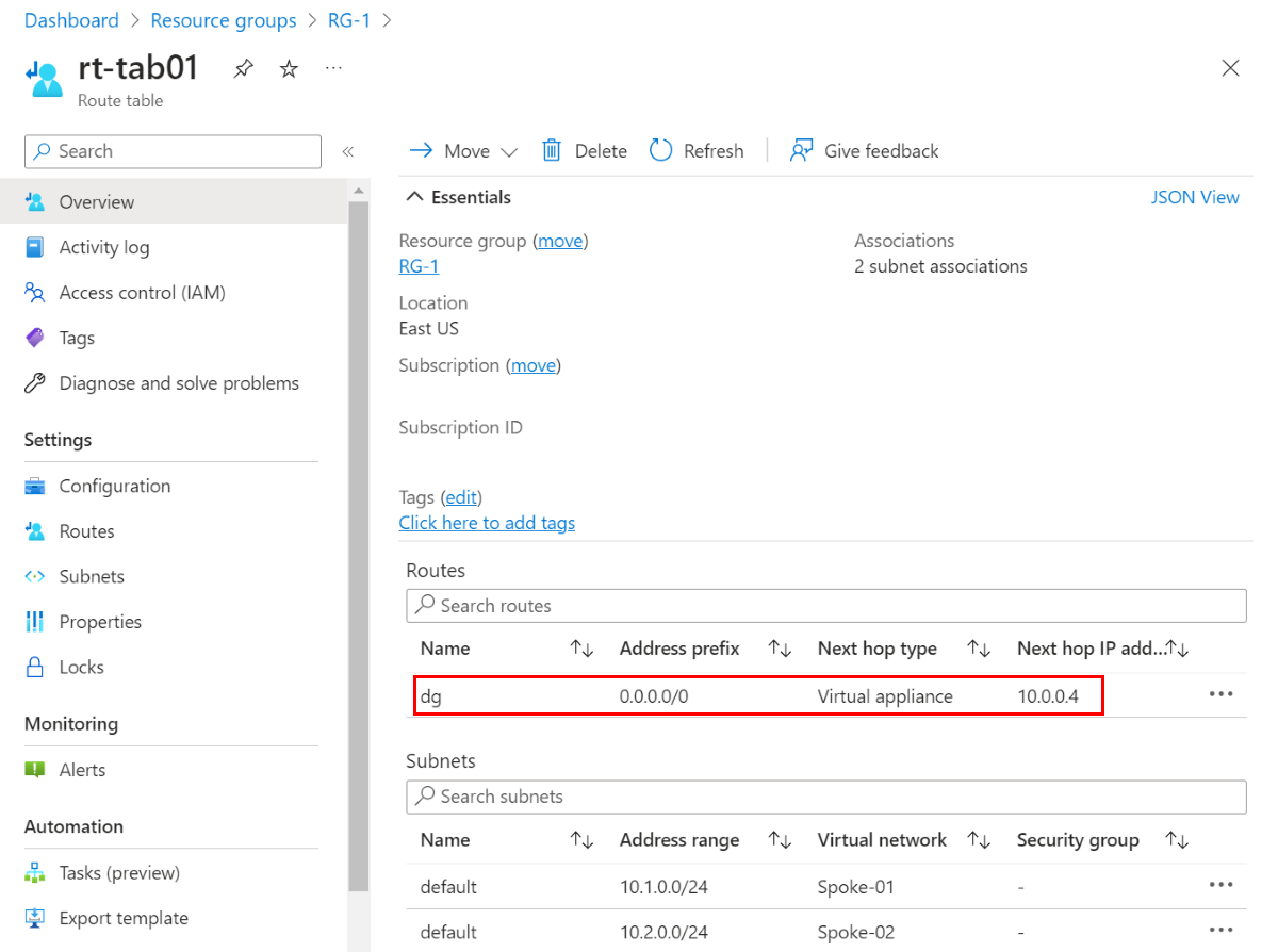
As shown in the diagram, it's best to place a UDR in the spoke subnets with a 0/0 route (default gateway) pointing to the local firewall as the next hop. This ensures a single exit point through the local firewall and reduces the risk of asymmetric routing if more specific prefixes from your on-premises environment cause traffic to bypass the firewall. For more information, see Don’t let your Azure Routes bite you.
Here's an example route table for the spoke subnets connected to Hub-01:
Next steps
- Learn how to deploy and configure an Azure Firewall.