Note
Access to this page requires authorization. You can try signing in or changing directories.
Access to this page requires authorization. You can try changing directories.
Load balancer provides several capabilities for both UDP and TCP applications.
Floating IP
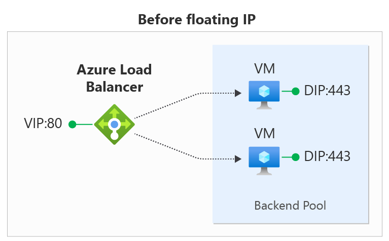
Some application scenarios prefer or require the use of the same port by multiple application instances on a single VM in the backend pool. Common examples of port reuse include clustering for high availability, network virtual appliances, and exposing multiple TLS endpoints without re-encryption. If you want to reuse the backend port across multiple rules, you must enable Floating IP in the rule definition. Enabling Floating IP allows for more flexibility.
| Floating IP status | Outcome |
|---|---|
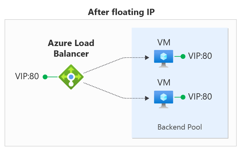
| Floating IP enabled | Azure changes the IP address mapping to the Frontend IP address of the Load Balancer |
| Floating IP disabled | Azure exposes the VM instances' IP address |
In the diagrams, you see how IP address mapping works before and after enabling Floating IP:
You configure Floating IP on a Load Balancer rule via the Azure portal, REST API, CLI, PowerShell, or other client. In addition to the rule configuration, you must also configure your virtual machine's Guest OS in order to use Floating IP.
The Floating IP rule type is the foundation of several load balancer configuration patterns. One example that is currently available is the Configure one or more Always On availability group listeners configuration. Over time, we'll document more of these scenarios.
Floating IP Guest OS configuration
In order to function, you configure the Guest OS for the virtual machine to receive all traffic bound for the frontend IP and port of the load balancer. Configuring the VM requires:
- adding a loopback network interface
- configuring the loopback with the frontend IP address of the load balancer
- ensuring the system can send/receive packets on interfaces that don't have the IP address assigned to that interface. Windows systems require setting interfaces to use the "weak host" model. For Linux systems, this model is normally used by default.
- configuring the host firewall to allow traffic on the frontend IP port.
Note
The examples below all use IPv4; to use IPv6, substitute "ipv6" for "ipv4".
Windows Server
Expand
For each VM in the backend pool, run the following commands at a Windows Command Prompt on the server.
To get the list of interface names you have on your VM, enter this command:
netsh interface ipv4 show interfaceFor the VM NIC (Azure managed), enter the following command after replacing interface-name with the name of the interface you want to use:
netsh interface ipv4 set interface <interface-name> weakhostreceive=enabledFor each loopback interface you added, enter these commands after replacing loopback-interface-name with the name of the loopback interface and floating-IP and floating-IPnetmask with the appropriate values that correspond to the load balancer frontend IP:
netsh interface ipv4 add addr <loopback-interface-name> <floating-IP> <floating-IPnetmask>
netsh interface ipv4 set interface <loopback-interface-name> weakhostreceive=enabled  weakhostsend=enabled
Finally, if the guest host uses a firewall, ensure a rule set up so the traffic can reach the VM on the appropriate ports. This example configuration assumes a load balancer frontend IP configuration of 1.2.3.4 and a load balancing rule for port 80:
netsh int ipv4 set int "Ethernet" weakhostreceive=enabled
netsh int ipv4 add addr "Loopback Pseudo-Interface 1" 1.2.3.4 255.255.255.0
netsh int ipv4 set int "Loopback Pseudo-Interface 1" weakhostreceive=enabled weakhostsend=enabled
netsh advfirewall firewall add rule name="http" protocol=TCP localport=80 dir=in action=allow enable=yes
Ubuntu
Expand
For each VM in the backend pool, run the following commands via an SSH session.
To get the list of interface names you have on your VM, type this command:
ip addrFor each loopback interface you added, enter these commands after replacing loopback-interface-name with the name of the loopback interface and floating-IP and floating-IPnetmask with the appropriate values that correspond to the load balancer frontend IP:
sudo ip addr add <floating-IP>/<floating-IPnetmask> dev lo:0Finally, if the guest host uses a firewall, ensure a rule set up so the traffic can reach the VM on the appropriate ports. This example configuration assumes a load balancer frontend IP configuration of 1.2.3.4, a load balancing rule for port 80, and the use of UFW (Uncomplicated Firewall) in Ubuntu.
sudo ip addr add 1.2.3.4/24 dev lo:0
sudo ufw allow 80/tcp
Limitations
- With Floating IP enabled on a load balancing rule, your application must use the primary IP configuration of the network interface for outbound.
- If your application binds to the frontend IP address configured on the loopback interface in the guest OS, Azure's outbound connection doesn't rewrite the outbound flow, and the flow fails. Review outbound scenarios.
- You can't use Floating IP on secondary IP configurations for Load Balancing scenarios. This limitation doesn't apply to Public load balancers where the secondary IP configuration is IPv6 and part of a dual-stack configuration, or to architectures that utilize a NAT Gateway for outbound connectivity.
Next steps
- Learn about using multiple frontends with Azure Load Balancer.
- Learn about Azure Load Balancer outbound connections.