Networking in Azure Operator Nexus Kubernetes
An Azure Operator Nexus, or simply Operator Nexus, instance comprises compute and networking hardware installed at the customer premises. Multiple layers of physical and virtual devices provide network connectivity and routing services to the workloads running on this compute hardware. This document provides a detailed description of each of these networking layers.
Topology
Here we describe the topology of hardware in an Operator Nexus instance.
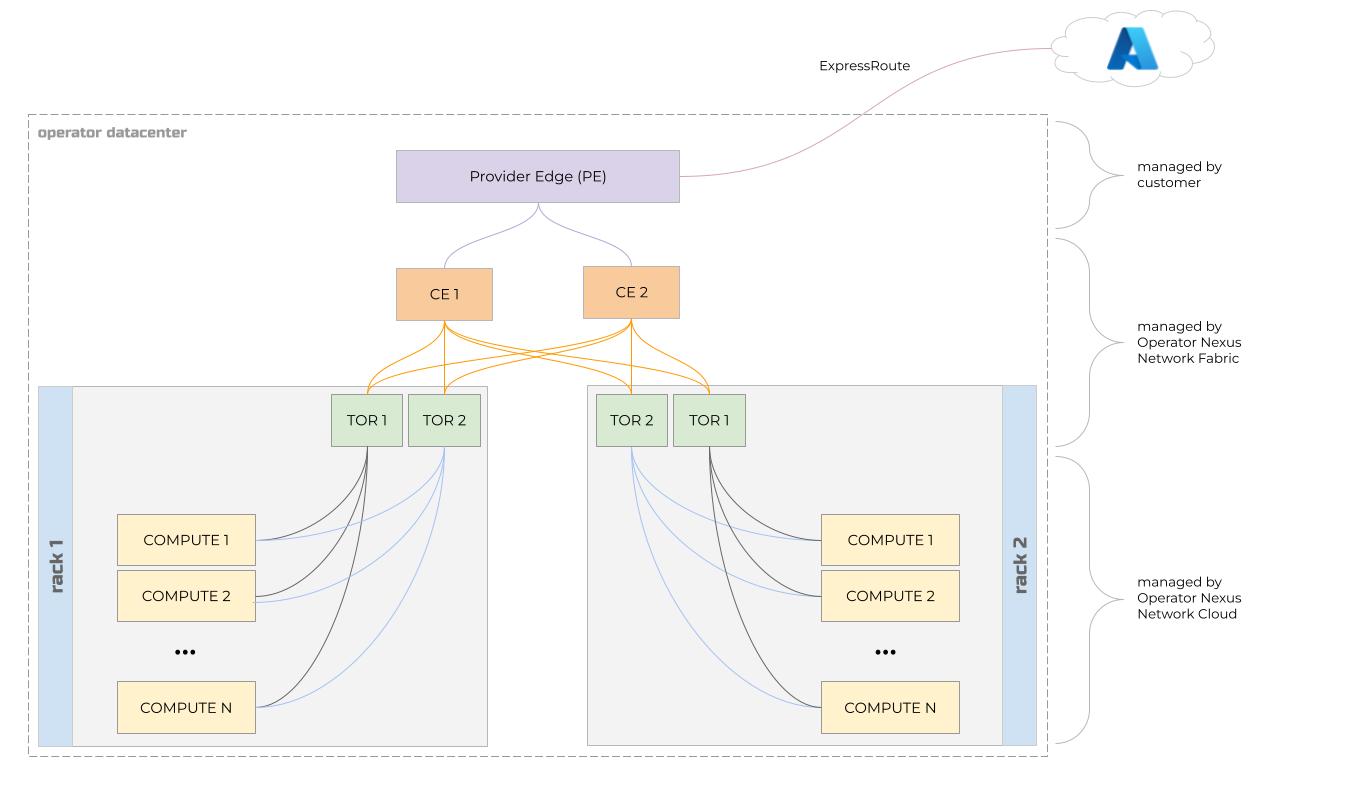
Customers own and manage Provider edge (PE) routers. These routers represent the edge of the customer’s backbone network.
Operator Nexus manages the customer edge (CE) routers. These routers are part of the Operator Nexus instance and are included in near-edge hardware bill of materials (BOM). There are two CE routers in each multi-rack Operator Nexus instance. Each CE router has an uplink to each of the PE routers. The CE routers are the only Operator Nexus devices that are physically connected to the customer’s network.
Each rack of compute servers in a multi-rack Azure Operator Nexus instance has two top-of-rack (TOR) switches. Each TOR has an uplink to each of the CE routers. Each TOR is connected to each bare metal compute server in the rack and is configured as a simple layer 2 switch.
Bare metal
Tenant workloads running on this compute infrastructure are typically virtual or containerized network functions. Virtual network functions (VNFs) run as virtual machines (VMs) on the compute server hardware. Containerized network functions (CNFs) run inside containers. These containers run on VMs that themselves run on the compute server hardware.
Network functions that provide end-user data plane services require high performance network interfaces that offer advanced features and high I/O rates.
In near-edge multi-rack Operator Nexus instances, each bare metal compute server is a dual-socket machine with Non-Uniform Memory Access (NUMA) architecture.
A bare metal compute server in a near-edge multi-rack Azure Operator Nexus instance contains one dual-port network interface card (pNIC) for each NUMA cell. These pNICs support Single-Root I/O Virtualization (SR-IOV) and other high-performance features. One NUMA cell is memory and CPU-aligned with a one pNIC.
All network interfaces assigned to tenant workloads are host passthrough devices and use SR-IOV virtual functions (VFs) allocated from the pNIC aligned to the NUMA cell housing the workload VM’s CPU and memory resources. This arrangement ensures optimal performance of the networking stack inside the VMs and containers that are assigned those VFs.
Compute racks are deployed with a pair of Top-of-Rack (TOR) switches. Each pNIC on each bare metal compute server is connected to both of those TORs. Multi-chassis link aggregation group (MLAG) provides high availability and link aggregation control protocol (LACP) provides increased aggregate throughput for the link.
Each bare metal compute server has a storage network interface that is provided by a bond that aggregates two host-local virtual functions (VF)s (as opposed to VM-local VFs) connected to both pNICs. These two VFs are aggregated in an active-backup bond to ensure if one of the pNICs fails, network storage connectivity remains available.
Logical network resources
When interacting with the Operator Nexus Network Cloud API and Managed Network Fabric APIs, users create and modify a set of logical resources.
Logical resources in the Managed Network Fabric API correspond to the networks
and access control configuration on the underlying networking hardware (the
TORs and CEs). Notably, ManagedNetworkFabric.L2IsolationDomain and
ManagedNetworkFabric.L3IsolationDomain resources contain low-level switch and
network configuration. A ManagedNetworkFabric.L2IsolationDomain represents a
virtual local area network identifier (VLAN). A
ManagedNetworkFabric.L3IsolationDomain represents a
virtual routing and forwarding configuration (VRF) on the CE routers.
Read about the concept of an Isolation Domain.
Logical resources in the Network Cloud API correspond to compute infrastructure. There are resources for physical racks and bare metal hardware. Likewise, there are resources for Kubernetes clusters and virtual machines that run on that hardware and the logical networks that connect them.
NetworkCloud.L2Network, NetworkCloud.L3Network, and
NetworkCloud.TrunkedNetwork all represent workload networks, meaning traffic
on these networks is meant for tenant workloads.
A NetworkCloud.L2Network represents a layer-2 network and contains little
more than a link to a ManagedNetworkFabric.L2IsolationDomain. This
L2IsolationDomain contains a VLAN identifier and a maximum transmission unit
(MTU) setting.
A NetworkCloud.L3Network represents a layer-3 network and contains a VLAN
identifier, information about IP address assignment for endpoints on the
network and a link to a ManagedNetworkFabric.L3IsolationDomain.
Note
Why does a NetworkCloud.L3Network resource contain a VLAN identifier?
Aren't VLANs a layer-2 concept?
Yes, yes they are! The reason for this is due
to the fact that the NetworkCloud.L3Network must be able to refer to a
specific ManagedNetworkFabric.InternalNetwork.
ManagedNetworkFabric.InternalNetworks are created within a specific
ManagedNetworkFabric.L3IsolationDomain and are given a VLAN identifier.
Therefore, in order to reference a specific
ManagedNetworkFabric.InternalNetwork, the NetworkCloud.L3Network must
contain both an L3IsolationDomain identifier and a VLAN identifier.
Logical network resources in the Network Cloud API such as
NetworkCloud.L3Network reference logical resources in the Managed Network
Fabric API and in doing so provide a logical connection between the physical
compute infrastructure and the physical network infrastructure.
When creating a Nexus Virtual Machine, you may specify zero or more L2, L3, and
Trunked Networks in the Nexus Virtual Machine's
NetworkAttachments. When creating a Nexus Kubernetes Cluster,
you may specify zero or more L2, L3, and Trunked Networks in the Nexus
Kubernetes Cluster's
NetworkConfiguration.AttachedNetworkConfiguration field.
AgentPools are collections of similar Kubernetes worker nodes within a Nexus
Kubernetes Cluster. You can configure each Agent Pool's attached L2, L3, and
Trunked Networks in the AgentPool's
AttachedNetworkConfiguration field.
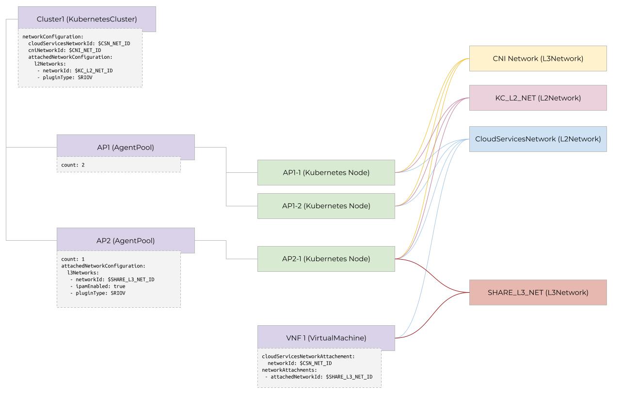
You can share networks across standalone Nexus Virtual Machines and Nexus Kubernetes Clusters. This composability allows you to stitch together CNFs and VNFs working in concert across the same logical networks.
The diagram shows an example of a Nexus Kubernetes cluster with two agent pools and a standalone Nexus Virtual Machine connected to different workload networks. Agent Pool "AP1" has no extra network configuration and therefore it inherits the KubernetesCluster's network information. Also note that all Kubernetes Nodes and all standalone Nexus Virtual Machines are configured to connect to the same Cloud Services Network. Finally, Agent Pool "AP2" and the stand-alone VM are configured to connect to a "Shared L3 Network".
The CloudServicesNetwork
Nexus Virtual Machines and Nexus Kubernetes Clusters always reference something called the "Cloud Services Network" (CSN). The CSN is a special network used for traffic between on-premises workloads and a set of external or Azure-hosted endpoints.
Traffic on the CloudServicesNetwork is routed through a proxy, where egress traffic is controlled via the use of an allowlist. Users can tune this allowlist using the Network Cloud API.
The CNI Network
When creating a Nexus Kubernetes Cluster, you provide the resource identifier
of a NetworkCloud.L3Network in the NetworkConfiguration.CniNetworkId field.
This "CNI network", sometimes referred to as "DefaultCNI Network", specifies the layer-3 network that provides IP addresses for Kubernetes Nodes in the Nexus Kubernetes cluster.
The diagram shows the relationships between some of the Network Cloud, Managed
Network Fabric, and Kubernetes logical resources. In the diagram, a
NetworkCloud.L3Network is a logical resource in the Network Cloud API that
represents a layer 3 network. The NetworkCloud.KubernetesCluster resource has
a field networkConfiguration.cniNetworkId that contains a reference to the
NetworkCloud.L3Network resource.
The NetworkCloud.L3Network resource is associated with a single
ManagedNetworkFabric.InternalNetwork resource via its l3IsolationDomainId
and vlanId fields. The ManagedNetworkFabric.L3IsolationDomain resource
contains one or more ManagedNetworkFabric.InternalNetwork resources, keyed by
vlanId. When the user creates the NetworkCloud.KubernetesCluster resource,
one or more NetworkCloud.AgentPool resources are created.
Each of these NetworkCloud.AgentPool resources comprises one or more virtual
machines. A Kubernetes Node resource represents each of those virtual
machines. These Kubernetes Node resources must get an IP address and the
Container Networking Interface (CNI) plugins on the virtual machines grab an IP
address from the pool of IP addresses associated with the
NetworkCloud.L3Network. The NetworkCloud.KubernetesCluster resource
references the NetworkCloud.L3Network via its cniNetworkId field. The
routing and access rules for those node-level IP addresses are contained in the
ManagedNetworkFabric.L3IsolationDomain. The NetworkCloud.L3Network refers
to the ManagedNetworkFabric.L3IsolationDomain via its l3IsoldationDomainId
field.
Operator Nexus Kubernetes networking
There are three logical layers of networking in Kubernetes:
- Node networking layer
- Pod networking layer
- Service networking layer
The Node networking layer provides connectivity between the Kubernetes control plane and the kubelet worker node agent.
The Pod networking layer provides connectivity between containers (Pods) running inside the Nexus Kubernetes cluster and connectivity between a Pod and one or more tenant-defined networks.
The Service networking layer provides load balancing and ingress functionality for sets of related Pods.
Node networking
Operator Nexus Kubernetes clusters house one or more containerized network functions (CNFs) that run on a virtual machines (VM). A Kubernetes Node represents a single VM. Kubernetes Nodes may be either Control Plane Nodes or Worker Nodes. Control Plane Nodes contain management components for the Kubernetes Cluster. Worker Nodes house tenant workloads.
Groups of Kubernetes Worker Nodes are called Agent Pools. Agent Pools are an Operator Nexus construct, not a Kubernetes construct.
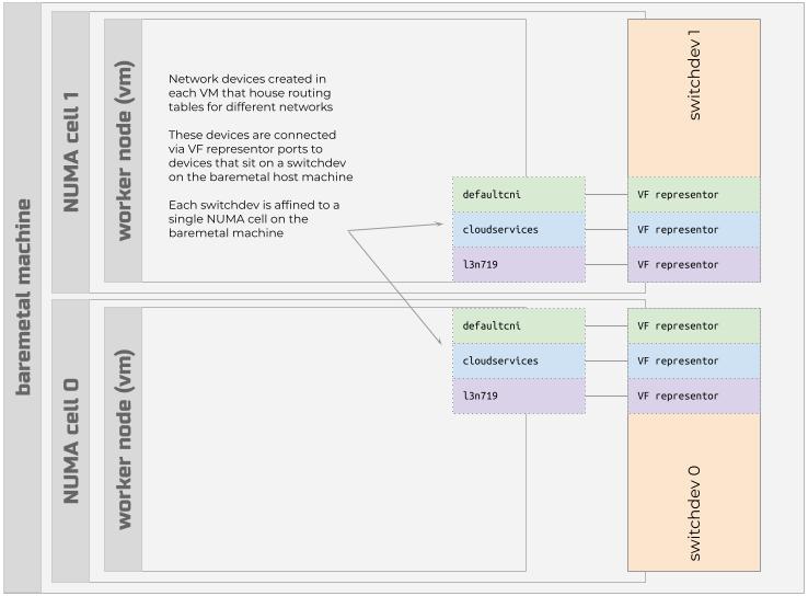
Each bare metal compute server in an Operator Nexus instance has a switchdev that is affined to a single NUMA cell on the bare metal server. The switchdev houses a set of SR-IOV VF representor ports that provide connectivity to a set of bridge devices that are used to house routing tables for different networks.
In addition to the defaultcni interface, Operator Nexus establishes a
cloudservices network interface on every Node. The cloudservices network
interface is responsible for routing traffic destined for external (to the
customer's premises) endpoints. The cloudservices network interface
corresponds to the NetworkCloud.CloudServicesNetwork API resource that the
user defines before creating a Nexus Kubernetes cluster. The IP address
assigned to the cloudservices network interface is a
link-local address, ensuring that external network traffic always
traverses this specific interface.
In addition to the defaultcni and cloudservices network interfaces,
Operator Nexus creates one or more network interfaces on each Kubernetes Node
that correspond to NetworkCloud.L2Network, NetworkCloud.L3Network, and
NetworkCloud.TrunkedNetwork associations with the Nexus Kubernetes cluster
or AgentPool.
Only Agent Pool VMs have these extra network interfaces. Control Plane VMs
only have the defaultcni and cloudservices network interfaces.
Node IP Address Management (IPAM)
Nodes in an Agent Pool receive an IP address from a pool of IP addresses
associated with the NetworkCloud.L3Network resource referred to in the
NetworkCloud.KubernetesCluster resource's networkConfiguration.cniNetworkId
field. This defaultcni network is the default gateway for all Pods that run
on that Node and serves as the default network for east-west Pod to Pod
communication within the Nexus Kubernetes cluster.
Pod networking
Kubernetes Pods are collections of one or more container images that run in a Linux namespace. This Linux namespace isolates the container’s processes and resources from other containers and processes on the host. For Nexus Kubernetes clusters, this "host" is a VM that is represented as a Kubernetes Worker Node.
Before creating an Operator Nexus Kubernetes Cluster, users first create a set
of resources that represent the virtual networks from which tenant workloads
are assigned addresses. These virtual networks are then referenced in the
cniNetworkId, cloudServicesNetworkId, agentPoolL2Networks,
agentPoolL3Networks, and agentPoolTrunkedNetworks fields when creating the
Operator Nexus Kubernetes Cluster.
Pods can run on any compute server in any rack in an Operator Nexus instance. By default all Pods in a Nexus Kubernetes cluster can communicate with each other over what is known as the pod network. Several Container Networking Interface (CNI) plugins that are installed in each Nexus Kubernetes Worker Node manage the Pod networking.
Extra Networks
When creating a Pod in a Nexus Kubernetes Cluster, you declare any extra
networks that the Pod should attach to by specifying a
k8s.v1.cni.cnf.io/networks annotation. The annotation's value is a
comma-delimited list of network names. These network names correspond to names
of any Trunked, L3 or L2 Networks associated with the Nexus Kubernetes Cluster
or Agent Pool.
Operator Nexus configures the Agent Pool VM with NetworkAttachmentDefinition (NAD) files that contain network configuration for a single extra network.
For each Trunked Network listed in the Pod's associated networks, the Pod gets a single network interface. The workload is responsible for sending raw tagged traffic through this interface or constructing tagged interfaces on top of the network interface.
For each L2 Network listed in the Pod's associated networks, the Pod gets a single network interface. The workload is responsible for their own static MAC addressing.
Pod IP Address Management
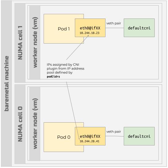
When you create a Nexus Kubernetes cluster, you specify the IP address ranges
for the pod network in the podCidrs field. When Pods launch, the CNI plugin
establishes an eth0@ifXX interface in the Pod and assigns an IP address from
a range of IP addresses in that podCidrs field.
For L3 Networks, if the network has been configured to use Nexus IPAM, the Pod's network interface associated with the L3 Network receives an IP address from the IP address range (CIDR) configured for that network. If the L3 Network isn't configured to use Nexus IPAM, the workload is responsible for statically assigning an IP address to the Pod's network interface.
Routing
Inside each Pod, the eth0 interface's traffic traverses a
virtual ethernet device (veth) that connects to a
switchdev on the host (the VM) that houses the defaultcni,
cloudservices, and other Node-level interfaces.
The eth0 interface inside a Pod has a simple route table that effectively
uses the worker node VM's route table for any of the following traffic.
- Pod to pod traffic: Traffic destined for an IP in the
podCidrsaddress ranges flows to the switchdev on the host VM and over the Node-leveldefaultcniinterface where it is routed to the appropriate destination agent pool VM's IP address. - L3 OSDevice network traffic: Traffic destined for an IP in an associated L3
Network with the
OSDeviceplugin type flows to the switchdev on the host VM and over the Node-level interface associated with that L3 Network. - All other traffic passes to the default gateway in the Pod, which routes to the
Node-level
cloudservicesinterface. Egress rules configured on the CloudServicesNetwork associated with the Nexus Kubernetes cluster then determine how the traffic should be routed.
Additional network interfaces inside a Pod will use the Pod's route table to
route traffic to additional L3 Networks that use the SRIOV and DPDK plugin
types.


