Note
Access to this page requires authorization. You can try signing in or changing directories.
Access to this page requires authorization. You can try changing directories.
This article describes the configuration options available for isolation domains.
Layer 3 isolation domain restricted within the fabric instance (E-W only traffic flows)
Creating a Layer-3 isolation domain with internal networks (so only on the ToR) enables communication between workloads deployed across racks by exchanging routes with the fabric. A single isolation domain can have multiple BGP peerings, each on a separate VLAN. BGP peering IP addresses can be a single IPv4 or IPv6 address, or a subnet to facilitate peering from multiple dynamic workload instances. BFD parameters can also be configured for each BGP peering. Import and export route policies can be defined to enforce policies on exchanged routes.
Layer 3 isolation domain that extends into the operator network (E-W + N-S traffic flows)
Creating a Layer-3 isolation domain with an external network enables inter-rack and intra-rack communication between workloads deployed across racks as well as the ability to exchange routes with the fabric and external networks via PE. North-bound peering with PE devices can be configured with either inter-AS option 10A or option 10B. When configured with inter-AS option 10B, route targets can be specified to segregate workload specific traffic. Multiple route-targets can be attached to each prefix.
You can deploy workloads that advertise external service IP addresses to PE devices via BGP, and load-balance traffic across multiple instances. You can also insert workload services (Firewalls, DNS, IPs) between north-south layers as explained in the next section.
Tenant networking use cases
Azure Operator Nexus is a platform that enables different types of communication between workloads:
East-West Communication: communication between workloads within the same Operator Nexus instance, such as inter-k8s cluster communication for a 5G control plane.
External-Internal Communication: communication between workloads inside and outside the instance. For example:
- North-south communication with option B, which involves inserting and scaling firewall and network address translation appliances.
- North-south communication between a 5G user plane with control plane.
In-line Appliance Insertion: communication between workloads that must pass through an appliance. For example:
- Virtual machine communication in a 4G core.
- Appliance insertion between two virtual routing and forwarding domains on the customer edge.
The following diagram shows a typical multi-layer communication setup required for a tenant's network use case.
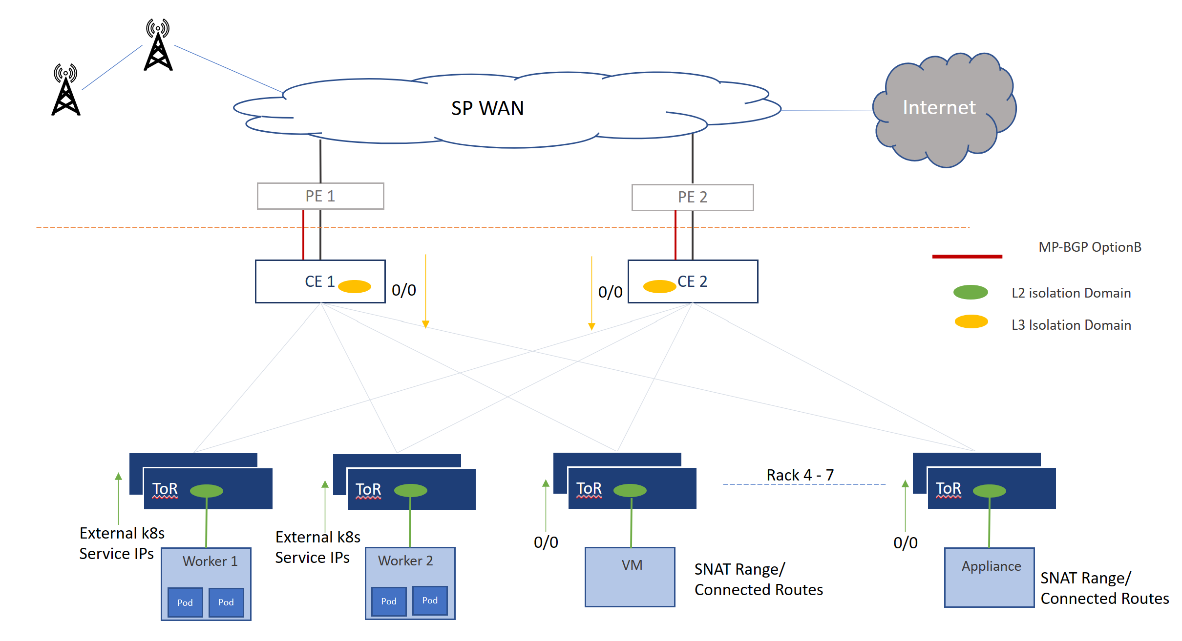
In the scenario shown in the picture, the Operator deploys Worker 1 and Worker 2 workloads using Kubernetes. A layer-2 isolation domain (represented in green) is created to allow communication between these workloads. The NAT FW/OAM FW performs SNAT on the IP addresses of the worker services and advertises the SNAT range to the PE via the network fabric. To provide this connectivity, an L3 isolation domain is created (represented in orange) on links to CEs.
To ensure all traffic from the worker nodes 0/0 route is advertised in the green layer-2 isolation domain. The FW instances SNAT the traffic and inject the traffic into the orange L3 ID. One interface of the Firewall instances in the diagram is in the orange layer-3 isolation domain. Combination of green layer-2 isolation domain and orange layer-3 isolation domains enable connectivity within the fabric for various workloads with ability to route the traffic towards the PE.
To advertise reachability of the workloads to external networks, north-bound peering is enabled in orange L3 isolation domain. The red line in the diagram represents peering via inter-AS Option A where BGP peering is enabled between the PE and CE explicitly in the L3 Isolation domain. The black line in the diagram represents peering via MPLS inter-AS Option B where MP-BGP peering is enabled between the PE and CE. You can use route targets to segregate traffic across L3 isolation domains. Route policy options enable operators to manipulate routes exchanged in north-south directions.
Configuration options
The following table gives detailed information about isolation domain configuration options.
| Feature | Details |
|---|---|
| Layer 2 connectivity |
|
| Layer 3 connectivity |
|
| Routing Configuration | BGP with connected subnets, static routing, and BFD |
| IP Addressing Support | Dual Stack (IPv4 and IPv6) support |
| Configurable parameters | VLANs, MTU, IPv4/IPv6 subnets, BGP. |
| Dynamic scale up and down | Workloads networks can be created dynamically. An L3 Isolation domain lets you advertise redistributed routes. |
Example scenarios and implementation- Isolation Domain with Internal Networks
This section provides examples of using L3 isolation domains and internal networks using BGP and static routes with IPv4 and IPv6 addresses.
Connected Subnet: An internal network for layer 3 communication. IPv4 and IPv6 are both supported. This option also enables the operator to specify a single neighbor, multiple neighbors, and a listen range for communication with the subnet.
Internal Network Multiple connected subnets IPv4: An internal network for layer 3 communication across multiple subnets. IPv4 and IPv6 are both supported. This option also enables the operator to specify either a single neighbor or multiple neighbors, and a listen range for communication with subnet.
The above options also give the operator the ability to send a default route to a neighbor or listen range. By default, no default route is advertised.
- Connected Subnet with Static Routes :: An internal network with static routes for communication with a connected subnet. The operator can optionally configure an IPv4 or IPv6 route by defining an IP prefix and the next single or multi-hop ip address. IPv4 and IPv6 are both supported. There's also an option to enable Bidirectional Forwarding Detection (BFD).
In all three cases, the internal network is associated with a Layer 3 isolation domain, allowing operators to apply route policy details, which can be referred to in a route policy guide.
Example scenarios and implementation - Isolation Domain with an External Network
An external network enables a workload to communicate with external services via the provider network as described earlier. This section describes some scenarios where you might use an L3 isolation domain with an external network.
External Network with MPLS OptionA: An external network between the CE and PE using peering OptionA. It uses the primary and secondary IP address prefixes of the CE-PE interconnect links.
External Network with MPLS OptionB: An external network between the CE and PE using peering OptionB with multiple route targets.
Both options support both IPv4 and IPv6 addresses. The operator can apply route policy details to the layer 3 network, which can be referred to in the route policy guide.