Note
Access to this page requires authorization. You can try signing in or changing directories.
Access to this page requires authorization. You can try changing directories.
In this article, you learn how to deploy multiple hub-and-spoke topologies, and manage user-defined routes (UDRs) with Azure Virtual Network Manager. This scenario is useful when you have a hub and spoke architecture in multiple Azure regions. In the past, customers with firewalls or network virtual appliances performed many manual operations to do cross-hub and spoke in the past. Users needed many user-defined routes(UDRs) to be set up by hand, and when there were changes in spoke virtual networks, such as adding new spoke virtual networks and subnets, they also needed to change user-defined routes and route tables. UDR management with Virtual Network Manager can help you automate these tasks.
Prerequisites
- An Azure subscription with a Virtual Network Manager deployed with UDR management enabled.
- Two hub-and-spoke topologies deployed in different Azure regions.
- Azure firewall instances deployed in each regional hub - total of two instances.
- Hub virtual networks in each region are peered with each other.
- Virtual machines deployed in the spoke virtual networks in each region to confirm network connectivity across regions.
Note
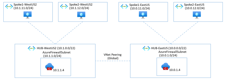
For this scenario, you have hub-and-spoke topologies deployed in two different Azure regions. Examples in this scenario will use West US 2 as the region1 placeholder and West US 3 as the region2 placeholder. You may use any other Azure regions as needed.
Create network groups
In this step, you deploy four network groups to represent the spoke virtual networks in each hub and spoke topology. You also create network groups for the subnet of the Azure firewall instances in each region.
| Network group name | Description | Member type | Members |
|---|---|---|---|
| ng-spoke-<region1> | Network group for spoke virtual networks in region 1. | Virtual network | Spoke virtual networks in region 1. |
| ng-spoke-<region2> | Network group for spoke virtual networks in region 2. | Virtual network | Spoke virtual networks in region 2. |
| ng-azfw-<region1> | Network group for Azure Firewall subnet in region 1. | Subnet | Azure Firewall subnet in region 1. |
| ng-azfw-<region2> | Network group for Azure Firewall subnet in region 2. | Subnet | Azure Firewall subnet in region 2. |
In the Azure portal, navigate to your network manager instance.
In the left pane, select Network groups under Settings.
Select + Create.
In the Create a network group window, enter the following details then select Create:
Field Value Name Enter ng-spoke-<region1> or the name of the network of the first hub virtual network in region one. Description Enter a description for the network group. Member type Select Virtual network from the dropdown menu. Repeat the steps create the remaining network groups for the spoke virtual networks in region 2 and the Azure Firewall subnets in each region based on the table above.
Add members to the network groups
In this step, you add the spoke virtual networks and Azure Firewall subnets to the network groups you created.
- In the network manager instance, navigate to Network groups under Settings.
- Select the network group for the spoke virtual networks in region 1 - ng-spoke-<region1>.
- Under Manage memberships of your network group, select Add virtual networks.
- In the Manually add members window, select the spoke virtual networks in region 1, then select Add.
Deploy hub and spoke topologies in each region
In this step, you create two connectivity configurations in your network manager instance to deploy hub and spoke topologies in each region. You create a connectivity configuration for each hub and spoke topology in each region.
- In your network manager instance, navigate to Configurations under Settings.
- Select + Create>Connectivity configuration.
- In the Basic tab of the Create a connectivity configuration window, enter a name and description for the first connectivity configuration.
- Select the Topology tab or Next: Topology.
- In the Topology tab, select the following details:
| Field | Value |
|---|---|
| Topology | Select Hub and spoke. |
| Hub | Choose Select a hub and select the hub virtual network in region 1. |
| Spoke network groups | Select Add. In the Add network groups window, select the spoke network groups from region 1: **ng-spoke-<region1>,**ng-spoke-<region2>* |
- Select the Visualization tab or Next: Visualization to review the topology.
- Select Review + create then Create and start deployment to deploy the connectivity configuration.
- In the Deploy a configuration window, select your configuration for region 1 under Connectivity configurations.
- Under Regions, select all regions where you want to deploy the configuration.
- Select Next and Deploy to deploy the configuration in region 1.
- Repeat the steps to create and deploy a connectivity configuration for the second hub and spoke topology in region 2.
Create a Routing configuration and Rule collections
In this step, you create a routing configuration containing four rule collections to manage the network groups created earlier.
| Rule collection name | Description | Target network group |
|---|---|---|
| rc-spoke-<region1> | Rule collection for spoke virtual networks in region 1. | ng-spoke-<region1> |
| rc-spoke-<region2> | Rule collection for spoke virtual networks in region 2. | ng-spoke-<region2> |
| rc-azfw-<region1> | Rule collection for Azure Firewall subnet in region 1. | ng-azfw-<region1> |
| rc-azfw-<region2> | Rule collection for Azure Firewall subnet in region 2. | ng-azfw-<region2> |
In your network manager instance, navigate to Configurations under Settings.
Select + Create>Routing configuration - Preview.
In the Create a routing configuration window, enter a name and description for the routing configuration.
Select Next: Rule collections or the Rule collections tab.
In the Rule collections tab, select + Add or Add.
In the Add a rule collection window, enter or select the following details, then select Add:
Field Value Name Enter a name for the rule collection for ng-spoke-<region1>. Description Enter a description for the rule collection. Local route setting Select Not specified. Target network group Select the network group for the spoke virtual networks in region 1. Repeat the steps to create rule collections for the remaining network groups: ng-spoke-<region2>, ng-azfw-<region1>, and ng-azfw-<region2>.
Select Add to add the rule collections to the routing configuration.
select Next: Review + create or Review + create to review the routing configuration.
Select Create to create the routing configuration.
Create routing rules for each Rule collection
In these steps, you create routing rules in each rule collection to manage traffic between the spoke virtual networks and the Azure Firewall subnets in each region.
Create a routing rule for spoke virtual networks in region 1
In this step, you create a routing rule for the spoke virtual networks in region 1 allowing communication with the Azure Firewall subnet in region 1.
In your network manager instance, navigate to Configurations under Settings.
Select the routing configuration you created for the spoke virtual networks in region 1.
In the left pane, select Rule collections and select your first rule collection - rc-spoke-<region1>.
In the Edit a rule collection window, select + Add.
In the Add a routing rule window, enter or select the following information:
Field Value Name Enter a name for the routing rule for. Destination type Select IP Address. Destination IP addresses/CIDR ranges Enter the default route of 0.0.0.0/0. Next hop type Select Virtual appliance.
Select Import Azure firewall private IP address. Select the Azure Firewall in region 1.Select Add to add the routing rule to the rule collection.
Select the X to close the Edit a rule collection window.
Create a routing rule for Azure Firewall in region 1
In these steps, you create a routing rule for the Azure Firewall subnet in region 1 allowing communication with the spoke virtual networks in region 2.
For this example, the remote regions address prefixes are summarized. Summarizing address prefixes offers the benefit of not needing to change the routing rules for the Azure firewall subnet even if new spokes are added to each region. However, it's important to predefine the address prefixes used in each region, including for future use.
In the Rule collections window, select the rule collection for the Azure Firewall subnet in region 1 - rc-azfw-<region1>.
In the Edit a rule collection window, select + Add.
In the Add a routing rule window, enter or select the following information:
Field Value Name Enter a name for the routing rule for. Destination type Select IP Address. Destination IP addresses/CIDR ranges Enter the summarized address prefix for the remote region - region 2. In this example, 10.1.0.0/16 is used. Next hop type Select Virtual appliance.
Select Import Azure firewall private IP address. Select the remote Azure Firewall in region 2.Select Add to add the routing rule to the rule collection.
select + Add to add a default Internet rule. In the Add a routing rule window, enter or select the following information:
Field Value Name Enter a name for the routing rule for. Destination type Select IP Address. Destination IP addresses/CIDR ranges Enter the default route of 0.0.0.0/0. Next hop type Select Internet. Select Add to add the routing rule to the rule collection.
Select the X to close the Edit a rule collection window.
Note
A summarized prefix allows you to use a larger address range for the destination IP addresses. This is useful when you have multiple spoke virtual networks in each region and you want to avoid adding multiple routing rules for each spoke virtual network. Also, future changes to the spoke virtual networks in each region will not require changes to the routing rules for the Azure Firewall subnet.
Create a routing rule for spoke virtual networks in region 2
In this step, you create a routing rule for the spoke virtual networks in region 2 allowing communication with the Azure Firewall subnet in region 2.
In the Rule collections window, select the rule collection for the spoke virtual networks in region 2 - rc-spoke-<region2>.
In the Edit a rule collection window, select + Add.
In the Add a routing rule window, enter or select the following information:
Field Value Name Enter a name for the routing rule for. Destination type Select IP Address. Destination IP addresses/CIDR ranges Enter the default route of 0.0.0.0/0. Next hop type Select Virtual appliance.
Select Import Azure firewall private IP address. Select the Azure Firewall in region 2.select + Add to add a default Internet rule. In the Add a routing rule window, enter or select the following information:
Field Value Name Enter a name for the routing rule for. Destination type Select IP Address. Destination IP addresses/CIDR ranges Enter the default route of 0.0.0.0/0. Next hop type Select Internet. Select Add to add the routing rule to the rule collection.
Select the X to close the Edit a rule collection window.
Create a routing rule for Azure Firewall in region 2
In these steps, you create a routing rule for the Azure Firewall subnet in region 2 allowing communication with the spoke virtual networks in region 1.
In the Rule collections window, select the rule collection for the Azure Firewall subnet in region 2 - rc-azfw-<region2>.
In the Edit a rule collection window, select + Add.
In the Add a routing rule window, enter or select the following information:
Field Value Name Enter a name for the routing rule for. Destination type Select IP Address. Destination IP addresses/CIDR ranges Enter the summarized address prefix for the remote region - region 1. In this example, 10.0.0.0/16 is used. Next hop type Select Virtual appliance.
Select Import Azure firewall private IP address. Select the remote Azure Firewall in region 1.Select Add to add the routing rule to the rule collection.
Select the X to close the Edit a rule collection window.
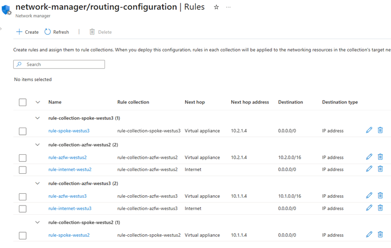
From the Rule collections window, select Rules under Settings, and review the listing of all rules in the routing configuration.

Deploy the routing configuration
In this step, you deploy the routing configuration to apply the routing rules to the spoke virtual networks and Azure Firewall subnets in each region.
- Browse to Configurations under Settings in your network manager instance.
- Select the checkbox next to the routing configuration you created, and select Deploy from the taskbar.
- In the Deploy a configuration window, select all regions where you want to deploy the routing configuration.
- Select Next and Deploy to deploy the routing configuration.
Confirm routing configuration
In this step, you confirm the routing configuration by reviewing the route tables applied to the subnets in each spoke virtual network.
In the Azure portal search bar, search and select Virtual networks.
In the Virtual networks window, select the one of the spoke virtual networks in region 1.
From the left menu, select Subnets and review settings for the subnets in the spoke virtual network.
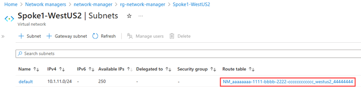
Under Route table, select the link staring with NM_ to view the route table applied to the subnet.
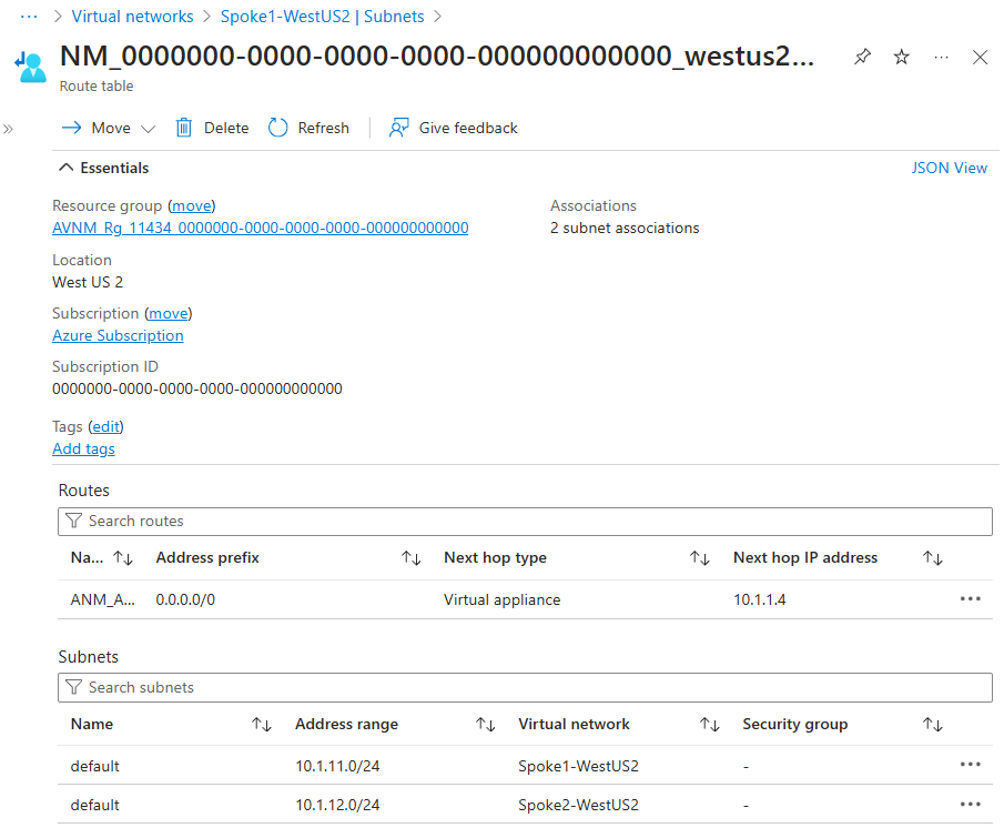
Close the route table and subnet window.
Repeat the steps to review the route tables applied to all the subnets in your configuration.

Adding a spoke virtual network to an existing multi-hub and spoke topology
When you add other virtual networks to a network group for spoke virtual networks, the connectivity and routing configurations are automatically applied to the new virtual network. Your network manager automatically detects the new virtual network and applies all applicable configurations. When you remove a virtual network from the network group, any applied configurations are automatically removed.