Note
Access to this page requires authorization. You can try signing in or changing directories.
Access to this page requires authorization. You can try changing directories.
Virtual WAN allows you to aggregate, connect, centrally manage, and secure all of your global deployments. Your global deployments could include any combinations of different branches, Point-of-Presence (PoP), private users, offices, Azure virtual networks, and other multi-cloud deployments. You can use SD-WAN, site-to-site VPN, point-to-site VPN, and ExpressRoute to connect your different sites to a virtual hub. If you have multiple virtual hubs, all the hubs would be connected in full mesh in a standard Virtual WAN deployment.
In this article, let's look into how to architect different types of network-as-a-service connectivity options that Virtual WAN supports for disaster recovery.
Network-as-a-service connectivity options of Virtual WAN
Virtual WAN supports following backend connectivity options:
- Remote user connectivity
- Branch/Office/SD-WAN/Site-to-site VPN
- Private connectivity (ExpressRoute private peering)
For each of these connectivity options, Virtual WAN deploys separate set of gateway instances within a virtual hub.
Inherently, Virtual WAN is designed to offer carrier-grade high-available network aggregation solution. For high availability, Virtual WAN instantiates multiple instances when each of these different types of gateways is deployed with in a Virtual WAN hub. To learn more about ExpressRoute high availability, see Designing for high availability with ExpressRoute.
With the point-to-site VPN gateway, the minimum number of instances deployed is two. With the point-to-site VPN gateway, you choose the aggregate throughput capacity of point to site gateways and multiple instances are automatically provisioned for you. You choose the aggregate capacity according to the number of clients or users you intend to connect to the virtual hub. From the client connectivity perspective, the point-to-site VPN gateway instances are hidden behind the Fully Qualified Domain Name (FQDN) of the gateway.
For the site-to-site VPN gateway, two instances of the gateway are deployed within a virtual hub. Each of the gateway instance is deployed with its own set of public and private IP addresses. The two instances provide two independent tunnel endpoints for establishing site-to-site VPN connectivity from your branches. To maximize high-availability, see Azure path selection across multiple ISP links.
Maximizing the high-availability of your network architecture is a key first step for Business Continuity and Disaster Recovery (BCDR). In the rest of this article, as stated previously, let's go beyond high-availability and discuss how to architect your Virtual WAN connectivity network for BCDR.
Need for disaster recovery design
Disaster might strike at any time, anywhere. Disaster might occur in a cloud provider regions or network, within a service provider network, or within an on-premises network. Regional impact of a cloud or network service due to certain factors such as natural calamity, human errors, war, terrorism, misconfiguration are hard to rule-out. So for the continuity of your business-critical applications you need to have a disaster recovery design. For a comprehensive disaster recovery design, you need to identify all the dependencies that might possibly fail in your end-to-end communication path, and create non-overlapping redundancy for each of the dependency.
Irrespective of whether you run your mission-critical applications in an Azure region, on-premises or anywhere else, you can use another Azure region as your failover site. The following articles addresses disaster recovery from applications and frontend access perspectives:
Challenges of using redundant connectivity
When you interconnect the same set of networks using more than one connection, you introduce parallel paths between the networks. Parallel paths, when not properly architected, could lead to asymmetrical routing. If you have stateful entities (for example, NAT, firewall) in the path, asymmetrical routing could block traffic flow. Typically, over private connectivity you won't have or come across stateful entities such as NAT or Firewalls. Therefore, asymmetrical routing over private connectivity doesn't necessarily block traffic flow.
However, if you load balance traffic across geo-redundant parallel paths, you would experience inconsistent network performance because of the difference in physical path of the parallel connections. So we need to consider network traffic performance both during the steady state (non-failure state), and a failure state as part of our disaster recovery design.
Access network redundancy
Most SD-WAN services (managed solutions or otherwise) provide network connectivity via multiple transport type (for example, Internet broadband, MPLS, LTE). To safeguard against transport network failures, choose connectivity over more than one transport network. For a home user scenario, you can consider using mobile network as a back-up for broadband network connectivity.
If network connectivity over different transport type isn't possible, then choose network connectivity via more than one service provider. If you're getting connectivity via more than one service providers, ensure that the service providers maintain non-overlapping independent access networks.
Remote user connectivity considerations
Remote user connectivity is established using point-to-site VPN between an end-device to a network. Following a network failure, the end-device would drop and attempt to re-establish the VPN tunnel. Therefore, for point-to-site VPN, your disaster recovery design should aim to minimize the recovery time following a failure. The following network redundancy would help minimize the recovery time. Depending on how critical the connections are you can choose some or all of these options.
- Access network redundancy (discussed above).
- Managing redundant virtual hub for point-to-site VPN termination. When you have multiple virtual hubs with point-to-site gateways, VWAN provides global profile listing all the point-to-site endpoints. With the global profile, your end-devices could connect to the closest available virtual hub that offers the best network performance. If all your Azure deployments are in a single region and the end devices that connect are in close proximity to the region, you can have redundant virtual hubs within the region. If your deployment and end-devices are spread across multiple regions, you can deploy virtual hub with point-to-site gateway in each of your selected region. Virtual WAN has a built-in traffic manager that selects the best hub for remote user connectivity automatically.
The following diagram shows the concept of managing redundant virtual hub with their respective point-to-site gateway within a region.
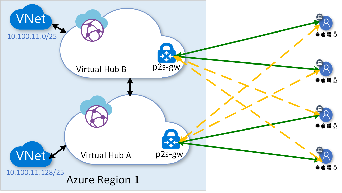
In the above diagram, the solid green lines show the primary point-to-site VPN connections and the dotted yellow lines show the stand-by back-up connections. The VWAN point-to-site global profile selects primary and back-up connections based on the network performance. See Download a global profile for User VPN clients for further information regarding global profile.
Site-to-site VPN considerations
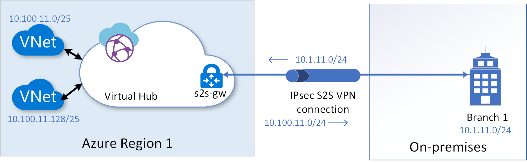
Let's consider the example site-to-site VPN connection shown in the following diagram for our discussion. To establish a site-to-site VPN connection with high-available active-active tunnels, see Tutorial: Create a Site-to-Site connection using Azure Virtual WAN.
Note
For easy understanding of the concepts discussed in the section, we are not repeating the discussion of the high-availability feature of site-to-site VPN gateway that lets you create two tunnels to two different endpoints for each VPN link you configure. However, while deploying any of the suggested architecture in the section, remember to configure two tunnels for each of the link you establish.
Multi-link topology
To protect against failures of VPN Customer Premises Equipment (CPE) at a branch site, you can configure parallel VPN links to a VPN gateway from parallel CPE devices at the branch site. Further to protect against network failures of a last-mile service provider to the branch office, you can configure different VPN links over different service provider network. The following diagram shows multiple VPN links originating from two different CPEs of a branch site terminating on the same VPN-gateway.
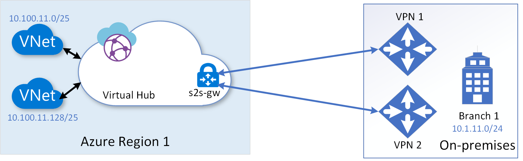
You can configure up to four links to a branch site from a virtual hub VPN gateway. While configuring a link to a branch site, you can identify the service provider and the throughput speed associated with the link. When you configure parallel links between a branch site and a virtual hub, the VPN gateway by default would load balance traffic across the parallel links. The load balancing of traffic would be according to Equal-Cost Multi-Path (ECMP) on per-flow basis.
Multi-hub multi-link topology
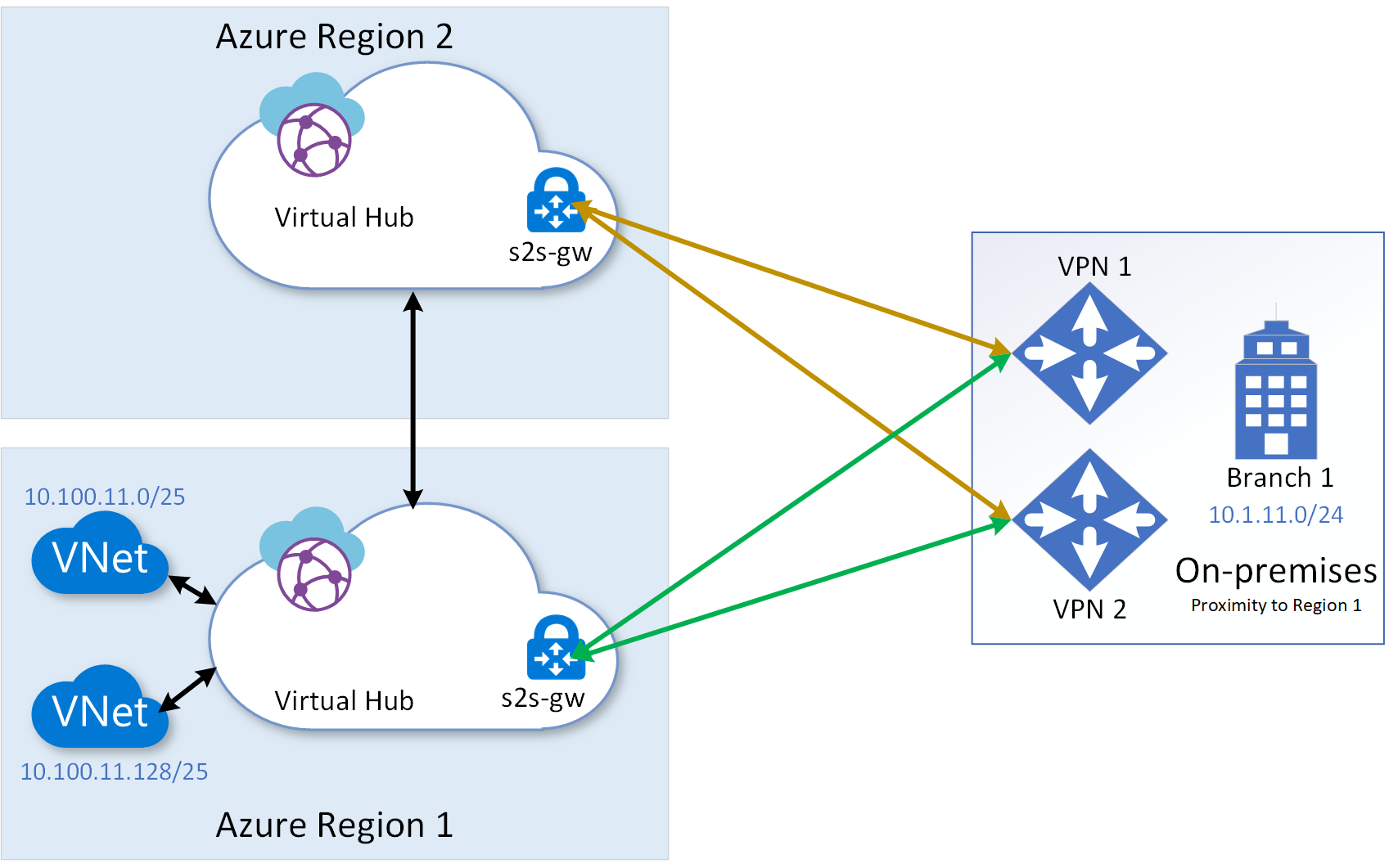
Multi-link topology protects against CPE device failures and a service provider network failure at the on-premises branch location. Additionally, to protect against any downtime of a virtual hub VPN-gateway, multi-hub multi-link topology would help. The following diagram shows the topology, in which multiple virtual hubs are configured under a Virtual WAN instance within a region:
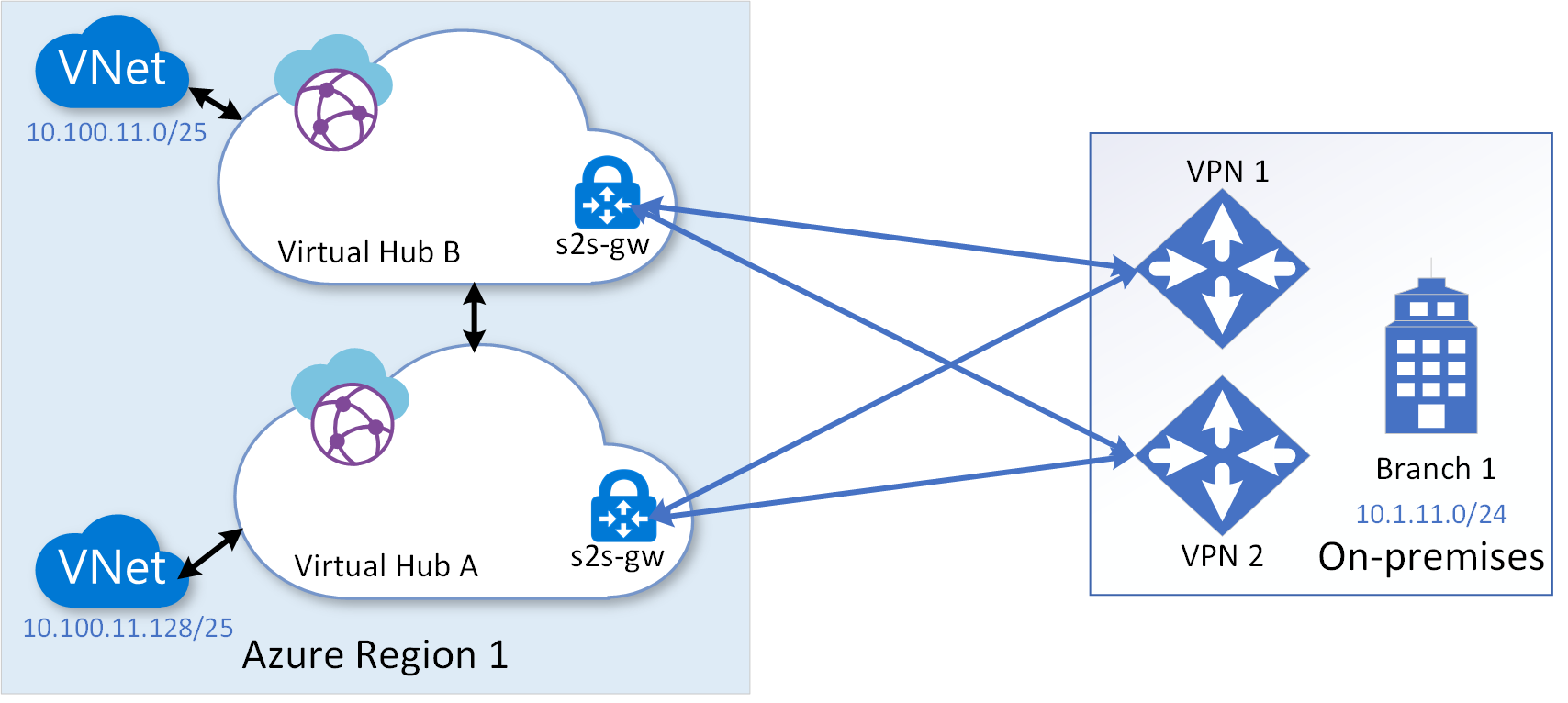
In the above topology, because intra-Azure-region latency over the connection between the hubs is insignificant, you can use all the site-to-site VPN connections between the on-premises and the two virtual hubs in active-active state by spreading the spoke VNets across the hubs. In the topology, by default, traffic between on-premises and a spoke virtual network would traverse directly through the virtual hub to which the spoke virtual network is connected during the steady-state and use another virtual hub as a backup only during a failure state. Traffic would traverse through the directly connected hub in the steady state, because the BGP routes advertised by the directly connected hub would have shorter AS-path compared to the backup hub.
The multi-hub multi-link topology would protect and provide business continuity against most of the failure scenarios. However, if a catastrophic failure takes down the entire Azure region, you need 'multi-region multi-link topology' to withstand the failure.
Multi-region multi-link topology
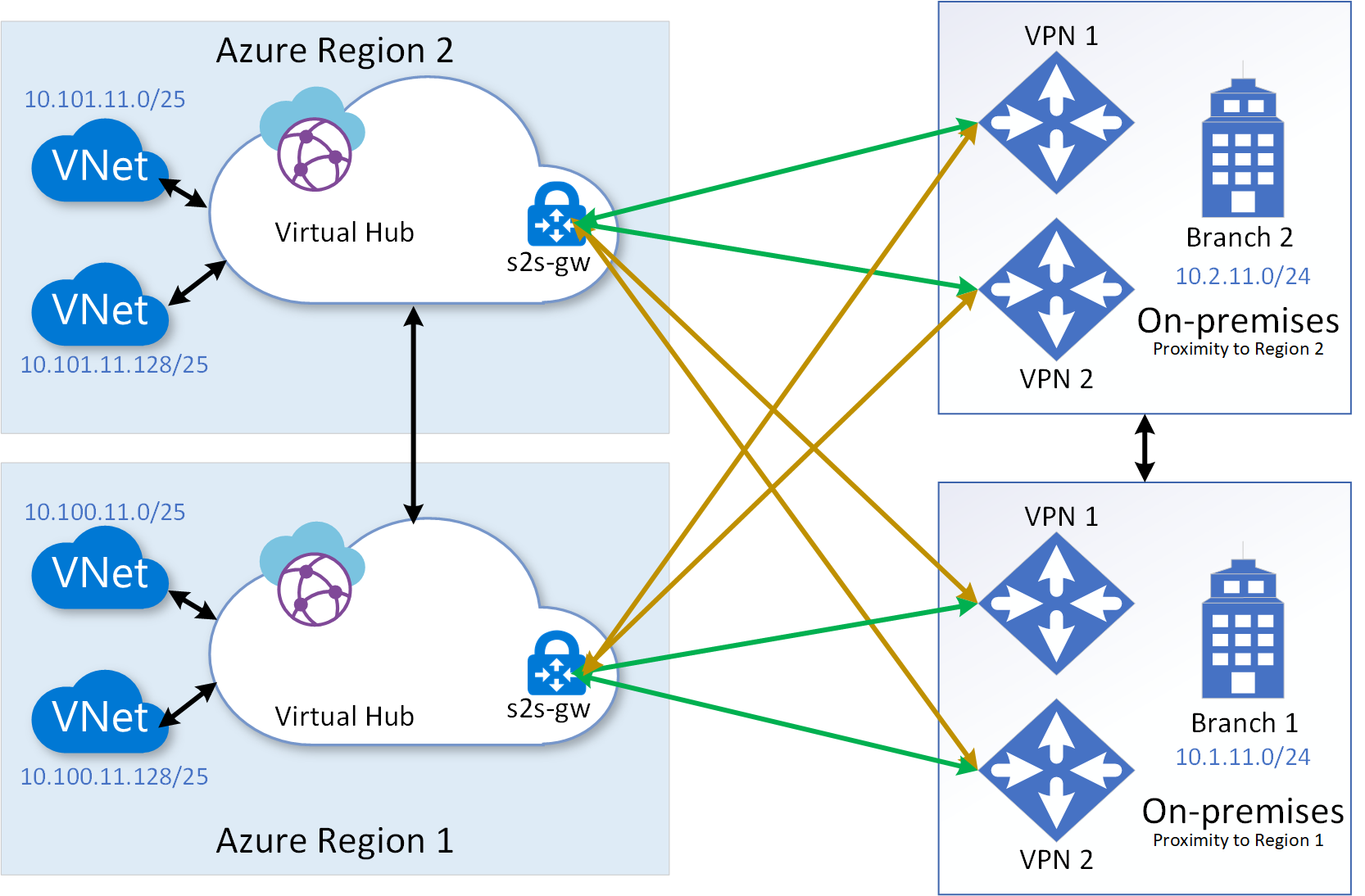
Multi-region multi-link topology protects against even a catastrophic failure of an entire region, in addition to the protections offered by the multi-hub multi-link topology that we previously discussed. The following diagram shows the multi-region multi-link topology. The virtual hubs in different region can be configured under the same Virtual WAN instance.
From a traffic engineering point of view, you need to take into consideration one substantial difference between having redundant hubs within a region vs having the backup hub in a different region. The difference is the latency resulting from the physical distance between the primary and secondary regions. Therefore, you may want to deploy your steady-state service resources in the region closest to your branch/end-users and use the remote region purely for backup.
If your on-premises branch locations are spread around two or more Azure regions, the multi-region multi-link topology would be more effective in spreading the load and in gaining better network experience during the steady state. The following diagram shows multi-region multi-link topology with branches in different regions. In such scenario, the topology would additionally provide effective Business Continuity Disaster Recovery (BCDR).
ExpressRoute considerations
Disaster recovery considerations for ExpressRoute private peering are discussed in Designing for disaster recovery with ExpressRoute private peering. As noted in the article, the concepts described in that article equally apply to ExpressRoute gateways created within a virtual hub. Using a redundant virtual hub within the region, as shown in the following diagram, is the only topology enhancement recommended for Small to medium on-premises network considerations.
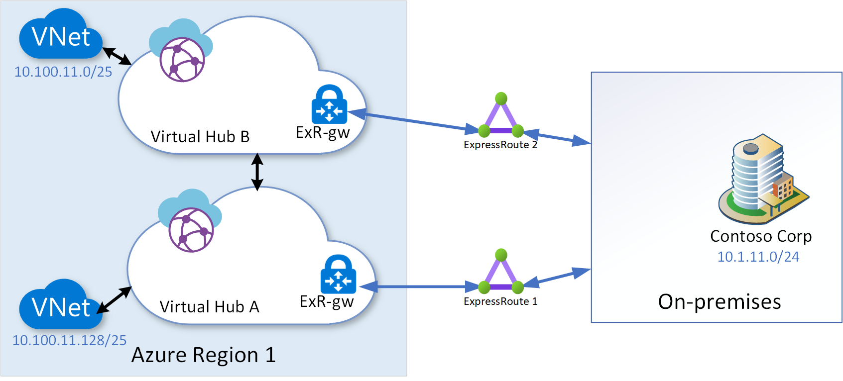
In the above diagram, the ExpressRoute 2 is terminated on a separate ExpressRoute gateway within a second virtual hub within the region.
Next steps
In this article, we discussed about Virtual WAN disaster recovery design. The following articles addresses disaster recovery from applications and frontend access perspectives:
To create a point-to-site connectivity to Virtual WAN, see Tutorial: Create a User VPN connection using Azure Virtual WAN. To create a site-to-site connectivity to Virtual WAN see Tutorial: Create a Site-to-Site connection using Azure Virtual WAN. To associate an ExpressRoute circuit to Virtual WAN, see Tutorial: Create an ExpressRoute association using Azure Virtual WAN.