Virtual WAN routing deep dive
Azure Virtual WAN is a networking solution that allows creating sophisticated networking topologies easily: it encompasses routing across Azure regions between Azure VNets and on-premises locations via Point-to-Site VPN, Site-to-Site VPN, ExpressRoute and integrated SDWAN appliances, including the option to secure the traffic. In most scenarios, it isn't required that you have deep knowledge of how Virtual WAN internal routing works, but in certain situations it can be useful to understand Virtual WAN routing concepts.
This document explores sample Virtual WAN scenarios that explain some of the behaviors that organizations might encounter when interconnecting their VNets and branches in complex networks. The scenarios shown in this article are by no means design recommendations, they're just sample topologies designed to demonstrate certain Virtual WAN functionalities.
Scenario 1: topology with default routing preference
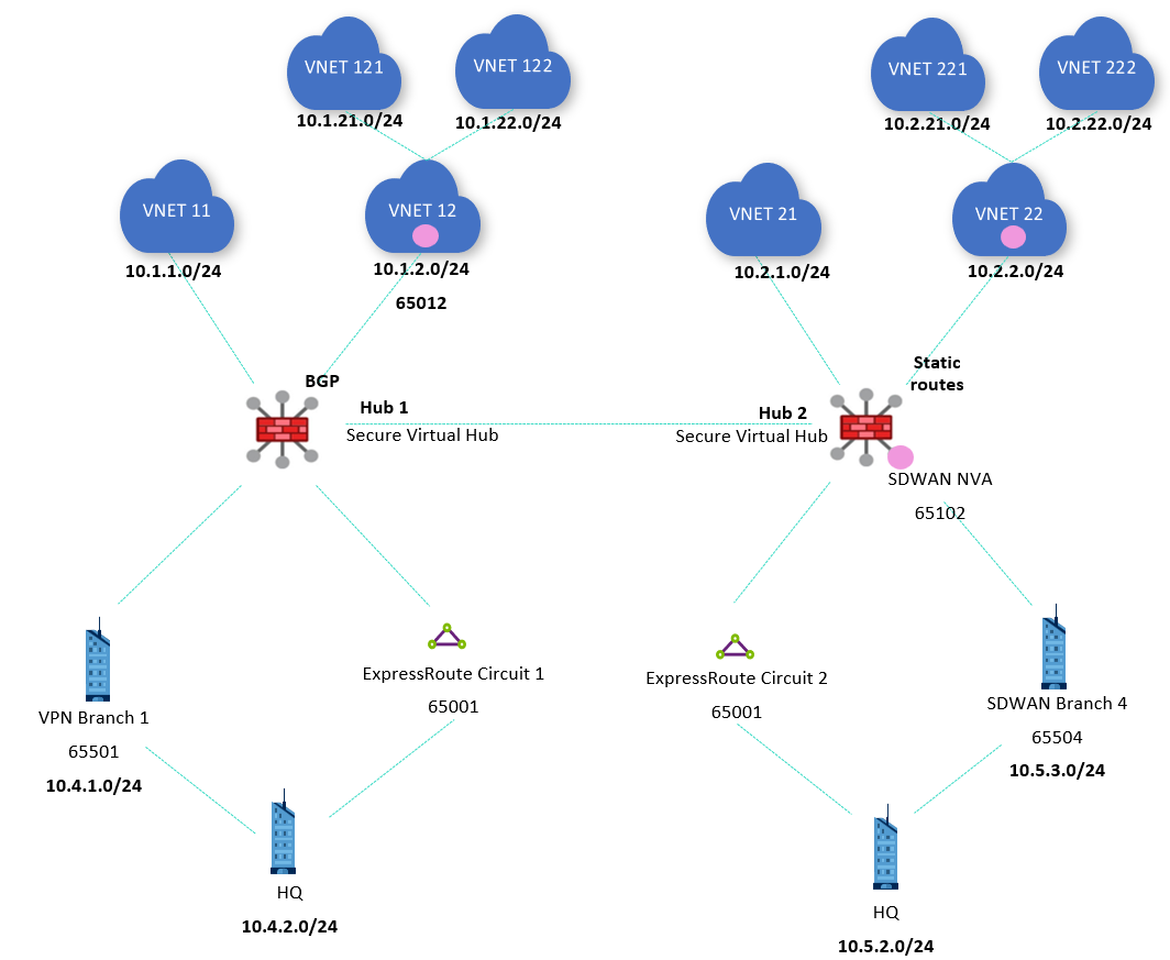
The first scenario in this article analyzes a topology with two Virtual WAN hubs, ExpressRoute, VPN and SDWAN connectivity. In each hub, there are VNets connected directly (VNets 11 and 21) and indirectly through an NVA (VNets 121, 122, 221 and 222). VNet 12 exchanges routing information with hub 1 via BGP (see BGP peering with a virtual hub), and VNet 22 has static routes configured, so that differences between both options can be shown.
In each hub, the VPN and SDWAN appliances serve a dual purpose: on one side they advertise their own individual prefixes (10.4.1.0/24 over VPN in hub 1 and 10.5.3.0/24 over SDWAN in hub 2), and on the other they advertise the same prefixes as the ExpressRoute circuits in the same region (10.4.2.0/24 in hub 1 and 10.5.2.0/24 in hub 2). This difference will be used to demonstrate how the Virtual WAN hub routing preference works.
All VNet and branch connections are associated and propagating to the default route table. Although the hubs are secured (there is an Azure Firewall deployed in every hub), they aren't configured to secure private or Internet traffic. Doing so would result in all connections propagating to the None route table, which would remove all non-static routes from the Default route table and defeat the purpose of this article since the effective route blade in the portal would be almost empty (except for the static routes to send traffic to the Azure Firewall).
Important
The previous diagram shows two secured virtual hubs, this topology is supported with Routing Intent. For more information see How to configure Virtual WAN Hub routing intent and routing policies.
Out of the box, the Virtual WAN hubs exchange information between each other so that communication across regions is enabled. You can inspect the effective routes in Virtual WAN route tables: for example, the following picture shows the effective routes in hub 1:

These effective routes will be then advertised by Virtual WAN to branches, and will inject them into the VNets connected to the virtual hubs, making the use of User Defined Routes unnecessary. When inspecting the effective routes in a virtual hub the "Next Hop Type" and "Origin" fields will indicate where the routes are coming from. For example, a Next Hop Type of "Virtual Network Connection" indicates that the prefix is defined in a VNet directly connected to Virtual WAN (VNets 11 and 12 in the previous screenshot)
The NVA in VNet 12 injects the route 10.1.20.0/22 over BGP, as the Next Hop Type "HubBgpConnection" implies (see BGP Peering with a Virtual Hub). This summary route covers both indirect spokes VNet 121 (10.1.21.0/24) and VNet 122 (10.1.22.0/24). VNets and branches in the remote hub are visible with a next hop of hub2, and it can be seen in the AS path that the Autonomous System Number 65520 has been prepended two times to these interhub routes.

In hub 2 there is an integrated SDWAN Network Virtual Appliance. For more details on supported NVAs for this integration please visit About NVAs in a Virtual WAN hub. Note that the route to the SDWAN branch 10.5.3.0/24 has a next hop of VPN_S2S_Gateway. This type of next hop can indicate today either routes coming from an Azure Virtual Network Gateway or from NVAs integrated in the hub.
In hub 2, the route for 10.2.20.0/22 to the indirect spokes VNet 221 (10.2.21.0/24) and VNet 222 (10.2.22.0/24) is installed as a static route, as indicated by the origin defaultRouteTable. If you check in the effective routes for hub 1, that route isn't there. The reason is because static routes aren't propagated via BGP, but need to be configured in every hub. Hence, a static route is required in hub 1 to provide connectivity between the VNets and branches in hub 1 to the indirect spokes in hub 2 (VNets 221 and 222):

After adding the static route, hub 1 will contain the 10.2.20.0/22 route as well:

Scenario 2: Global Reach and hub routing preference
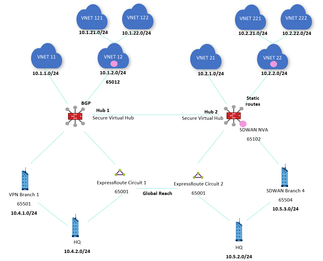
Even if hub 1 knows the ExpressRoute prefix from circuit 2 (10.5.2.0/24) and hub 2 knows the ExpressRoute prefix from circuit 1 (10.4.2.0/24), ExpressRoute routes from remote regions aren't advertised back to on-premises ExpressRoute links. Consequently, ExpressRoute Global Reach is required for the ExpressRoute locations to communicate to each other:
Important
The previous diagram shows two secured virtual hubs, this topology is supported with Routing Intent. For more information see How to configure Virtual WAN Hub routing intent and routing policies.
As explained in Virtual hub routing preference, Virtual WAN favors routes coming from ExpressRoute per default. Since routes are advertised from hub 1 to the ExpressRoute circuit 1, from the ExpressRoute circuit 1 to the circuit 2, and from the ExpressRoute circuit 2 to hub 2 (and vice versa), virtual hubs prefer this path over the more direct inter hub link now. The effective routes in hub 1 show this:

As you can see in the routes, ExpressRoute Global Reach prepends the ExpressRoute Autonomous System Number (12076) multiple times before sending routes back to Azure to make these routes less preferable. However, Virtual WAN default hub routing precedence of ExpressRoute ignores the AS path length when taking routing decision.
The effective routes in hub 2 will be similar:

The routing preference can be changed to VPN or AS-Path as explained in Virtual hub routing preference. For example, you can set the preference to VPN as shown in this image:

With a hub routing preference of VPN, the effective routes in hub 1 look like this:

The previous image shows that the route to 10.4.2.0/24 has now a next hop of VPN_S2S_Gateway, while with the default routing preference of ExpressRoute it was ExpressRouteGateway. However, in hub 2 the route to 10.5.2.0/24 will still appear with a next hop of ExpressRoute, because in this case the alternative route doesn't come from a VPN Gateway but from an NVA integrated in the hub:

However, traffic between hubs is still preferring the routes coming via ExpressRoute. To use the more efficient direct connection between the virtual hubs, the route preference can be set to "AS Path" on both hubs:

Now the routes for remote spokes and branches in hub 1 will have a next hop of Remote Hub as intended:

You can see that the IP prefix for hub 2 (192.168.2.0/23) still appears reachable over the Global Reach link, but this shouldn't impact traffic as there shouldn't be any traffic addressed to devices in hub 2. This route might be an issue though, if there were NVAs in both hubs establishing SDWAN tunnels between each other.
However, note that 10.4.2.0/24 is now preferred over the VPN Gateway. This can happen if the routes advertised via VPN have a shorter AS path than the routes advertised over ExpressRoute. After configuring the on-premises VPN device to prepend its Autonomous System Number (65501) to the VPN routes to make the less preferable, hub 1 now selects ExpressRoute as next hop for 10.4.2.0/24:

Hub 2 will show a similar table for the effective routes, where the VNets and branches in the other hub now appear with Remote Hub as next hop:

Scenario 3: Cross-connecting the ExpressRoute circuits to both hubs
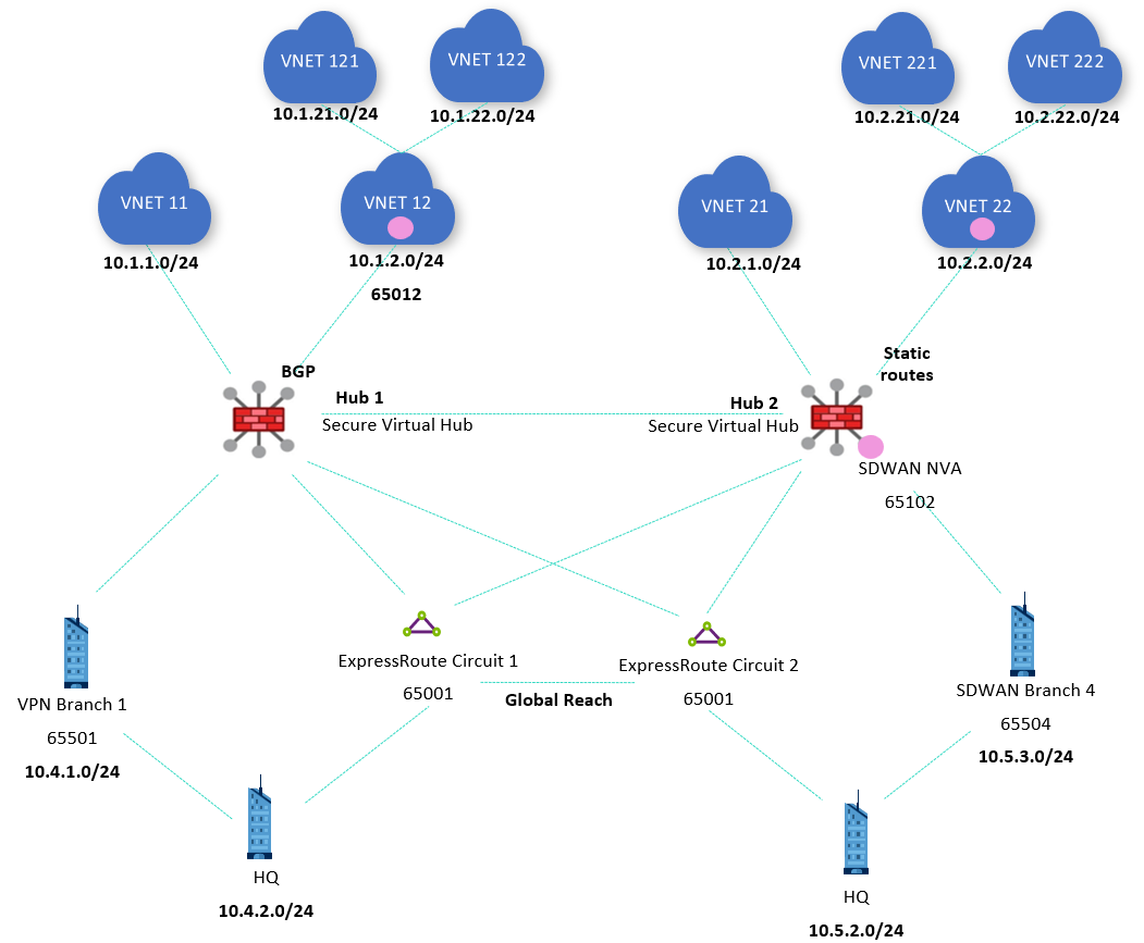
In order to add direct links between the Azure regions and the on-premises locations connected via ExpressRoute, it's often desirable connecting a single ExpressRoute circuit to multiple Virtual WAN hubs in a topology some times described as "bow tie", as the following topology shows:
Important
The previous diagram shows two secured virtual hubs, this topology is supported with Routing Intent. For more information, see How to configure Virtual WAN Hub routing intent and routing policies.
Virtual WAN shows that both circuits are connected to both hubs:

Going back to the default hub routing preference of ExpressRoute, the routes to remote branches and VNets in hub 1 will show again ExpressRoute as next hop. Although this time the reason isn't Global Reach, but the fact that the ExpressRoute circuits bounce back the route advertisements they get from one hub to the other. For example, the effective routes of hub 1 with hub routing preference of ExpressRoute are as follows:

Changing back the hub routing preference again to AS Path returns the inter hub routes to the optimal path using the direct connection between hubs 1 and 2:

Next steps
For more information about Virtual WAN, see:
- The Virtual WAN FAQ
Feedback
Coming soon: Throughout 2024 we will be phasing out GitHub Issues as the feedback mechanism for content and replacing it with a new feedback system. For more information see: https://aka.ms/ContentUserFeedback.
Submit and view feedback for