Scenario: Connect to Microsoft 365 via Virtual WAN using ExpressRoute private peering
This article walks you through a solution using Virtual WAN to create a connection to Microsoft 365 using Azure Virtual WAN and ExpressRoute private peering. A few examples of when you might want to use this type of connection are:
- The customer is in an area where internet isn't available.
- The customer is in a highly regulated environment.
In many cases, Microsoft doesn't recommend using Azure ExpressRoute with Microsoft peering to connect to Microsoft 365. When you aren't using Azure Virtual WAN, the most common concerns are:
- Implementing Azure ExpressRoute can be complex when it comes to routing.
- The use of Public IP addresses for the peering.
- ExpressRoute is normally against Microsoft Edge distribution policy.
- Egress costs can have a high-cost implication.
- Cost and scalability are normally not comparable to premium internet connections and higher.
While it's possible for you to request that the subscription allowlists use Microsoft 365 via Azure ExpressRoute, this still doesn't remove the limitations and implications listed above.
When you use Virtual WAN and ExpressRoute with private peering for your solution, you can keep down costs and enable redundancy. The solution in this article uses default behavior from the Microsoft global network in combination with Microsoft services. Microsoft service traffic is always transported on the Microsoft global network. For more information, see Microsoft global network.
The technologies engaged in this solution are:
- Azure ExpressRoute local.
- Azure Virtual WAN secured virtual hub.
- Firewall Appliance that is capable of service-based routing.
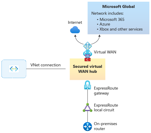
Architecture
The architecture is simple. However, when using this Virtual WAN solution, the ExpressRoute circuit isn't geo-redundant because it's only deployed in one edge co-location. To establish the necessary geo-redundancy, you must build additional ExpressRoute circuits.
Figure 1
Workflow
1. Deploy a virtual hub with Azure Firewall
First, deploy an Azure Virtual WAN hub with Azure Firewall. Azure Firewall is used not only to make the solution secure, but also as an Internet access point. For steps, see Install Azure Firewall in a Virtual WAN hub.
Figure 2

2. Deploy ExpressRoute gateway and connections
Next, deploy an Azure Virtual WAN ExpressRoute gateway into the Virtual WAN connection. Then, connect your ExpressRoute local to the gateway and secure Internet for that ExpressRoute. That will announce a default route (0.0.0.0/0) to your on-premises environment. For steps, see Create ExpressRoute connections using Azure Virtual WAN.
Figure 3

3. Set static route
From on-premises, you can now set a static route to point to the gateway. Or, you can use newer SDWAN or firewall devices to use service-based routing and only send traffic for Microsoft 365 Services to the secured Virtual WAN hub. For steps, see Install Azure Firewall in a Virtual WAN hub.
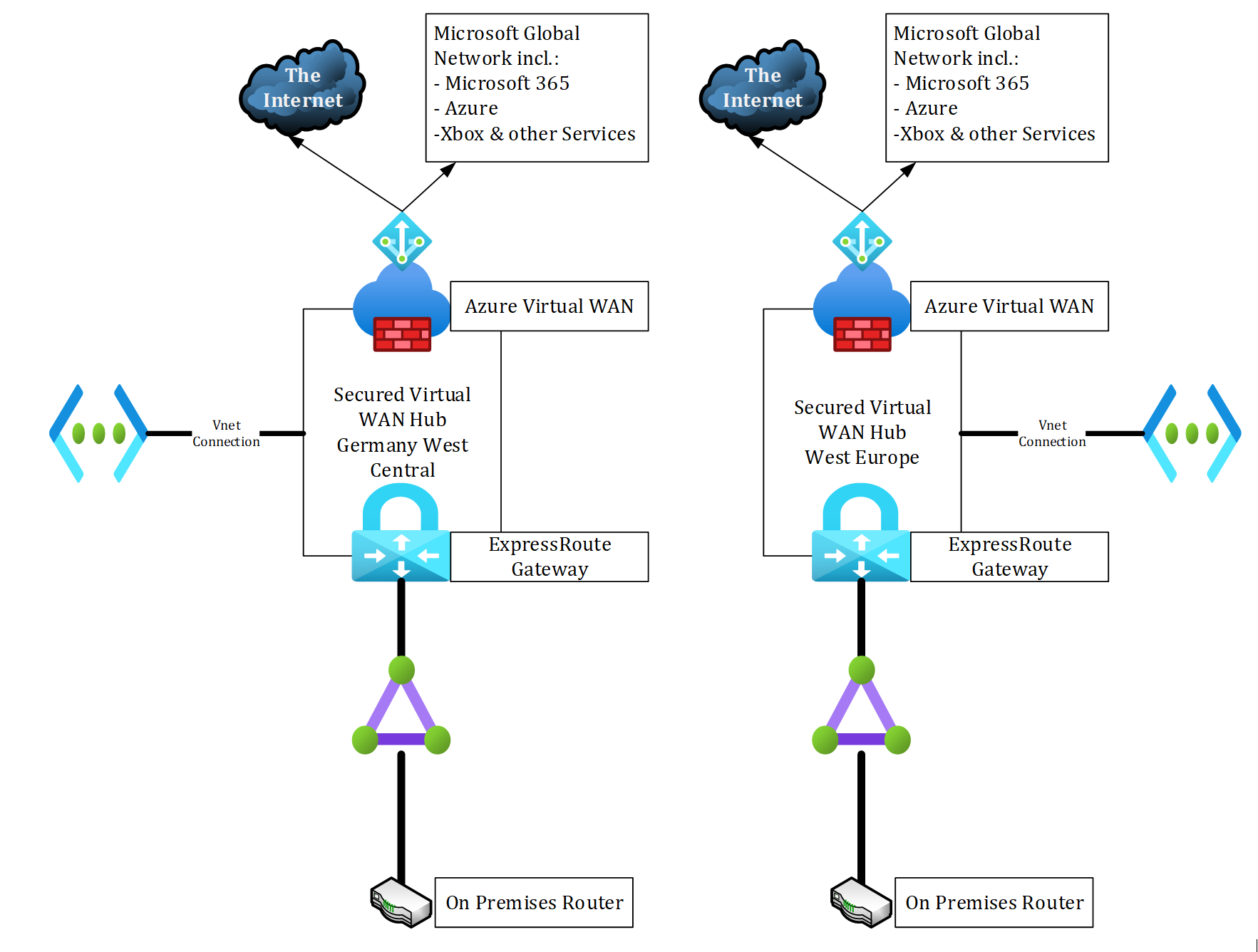
4. Build ExpressRoute circuit for geo-redundancy
To implement a highly available architecture and improve latency for your user, you should distribute additional hubs. We suggest putting ExpressRoute circuits in different locations. For example, in Germany Frankfurt and West Europe Amsterdam. For a list of ExpressRoute locations and providers, see the ExpressRoute locations and connectivity providers article.
You have two design options for this configuration:
- Option 1: Create two separate circuits connected to two separate hubs (Figure 4).
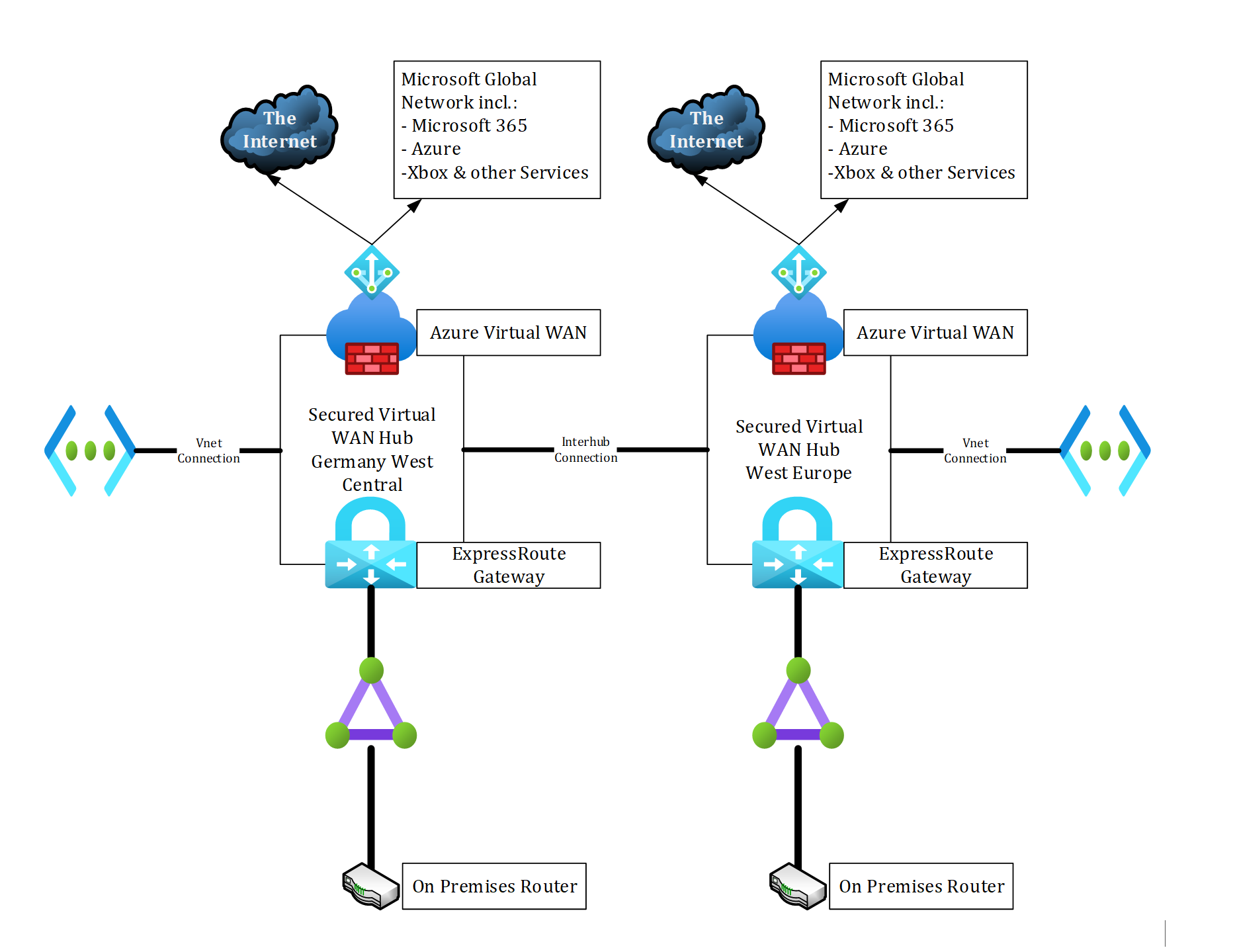
- Option 2: Interconnect both Virtual WAN hubs (Figure 5), then disable branch-to-branch connectivity within the virtual hub properties (Figure 6). With this option, the result is a private, redundant, high performant connection to Microsoft 365 services.
Option 1: Figure 4
Option 2: Figure 5
Option 2: Figure 6
