Scenario: Route traffic through NVAs by using custom settings
Article
When you're working with Azure Virtual WAN virtual hub routing, you have many options available to you. The focus of this article is when you want to route traffic through a network virtual appliance (NVA) for communication between virtual networks and branches, and use a different NVA for internet-bound traffic. For more information, see About virtual hub routing.
Note
Please note that for the routing scenarios below, the Virtual WAN hub and Spoke Virtual Network containing the NVA must be in the same Azure Region.
Design
Spokes for virtual networks connected to the virtual hub. (For example, VNet 1, VNet 2, and VNet 3 in the diagram later in this article.)
Service VNet for virtual networks where users have deployed an NVA to inspect non-internet traffic, and possibly with common services accessed by spokes. (For example, VNet 4 in the diagram later in this article.)
Perimeter VNet for virtual networks where users have deployed an NVA to be used to inspect internet-bound traffic. (For example, VNet 5 in the diagram later in this article.)
Hubs for Virtual WAN hubs managed by Microsoft.
The following table summarizes the connections supported in this scenario:
From
To
Spokes
Service VNet
Branches
Internet
Spokes
->
directly
directly
through Service VNet
through Perimeter VNet
Service VNet
->
directly
n/a
directly
Branches
->
through Service VNet
directly
directly
Each of the cells in the connectivity matrix describes whether connectivity flows directly over Virtual WAN or over one of the virtual networks with an NVA.
Note the following details:
Spokes:
Spokes will reach other spokes directly over Virtual WAN hubs.
Spokes will get connectivity to branches via a static route pointing to the Service VNet. They don't learn specific prefixes from the branches, because those prefixes are more specific and override the summary.
Spokes will send internet traffic to the Perimeter VNet through a direct VNet peering.
Branches will get to spokes via a static routing pointing to the Service VNet. They don't learn specific prefixes from the virtual networks that override the summarized static route.
The Service VNet will be similar to a Shared Services VNet that needs to be reachable from every virtual network and every branch.
The Perimeter VNet doesn't need to have connectivity over Virtual WAN, because the only traffic it will support comes over direct virtual network peerings. To simplify configuration, however, use the same connectivity model as for the Perimeter VNet.
There are three distinct connectivity patterns, which translate to three route tables. The associations to the different virtual networks are:
Spokes:
Associated route table: RT_V2B
Propagating to route tables: RT_V2B and RT_SHARED
NVA VNets (Service VNet and DMZ VNet):
Associated route table: RT_SHARED
Propagating to route tables: RT_SHARED
Branches:
Associated route table: Default
Propagating to route tables: RT_SHARED and Default
Note
Please make sure that the spoke VNets are not propagating to the Default label. This ensures traffic from branches to spoke VNets is forwarded to the NVAs.
These static routes ensure that traffic to and from the virtual network and branch goes through the NVA in the Service VNet (VNet 4):
Description
Route table
Static route
Branches
RT_V2B
10.2.0.0/16 -> vnet4conn
NVA spokes
Default
10.1.0.0/16 -> vnet4conn
Now you can use Virtual WAN to select the correct connection to send the packets to. You also need to use Virtual WAN to select the correct action to take when receiving those packets. You use the connection route tables for this, as follows:
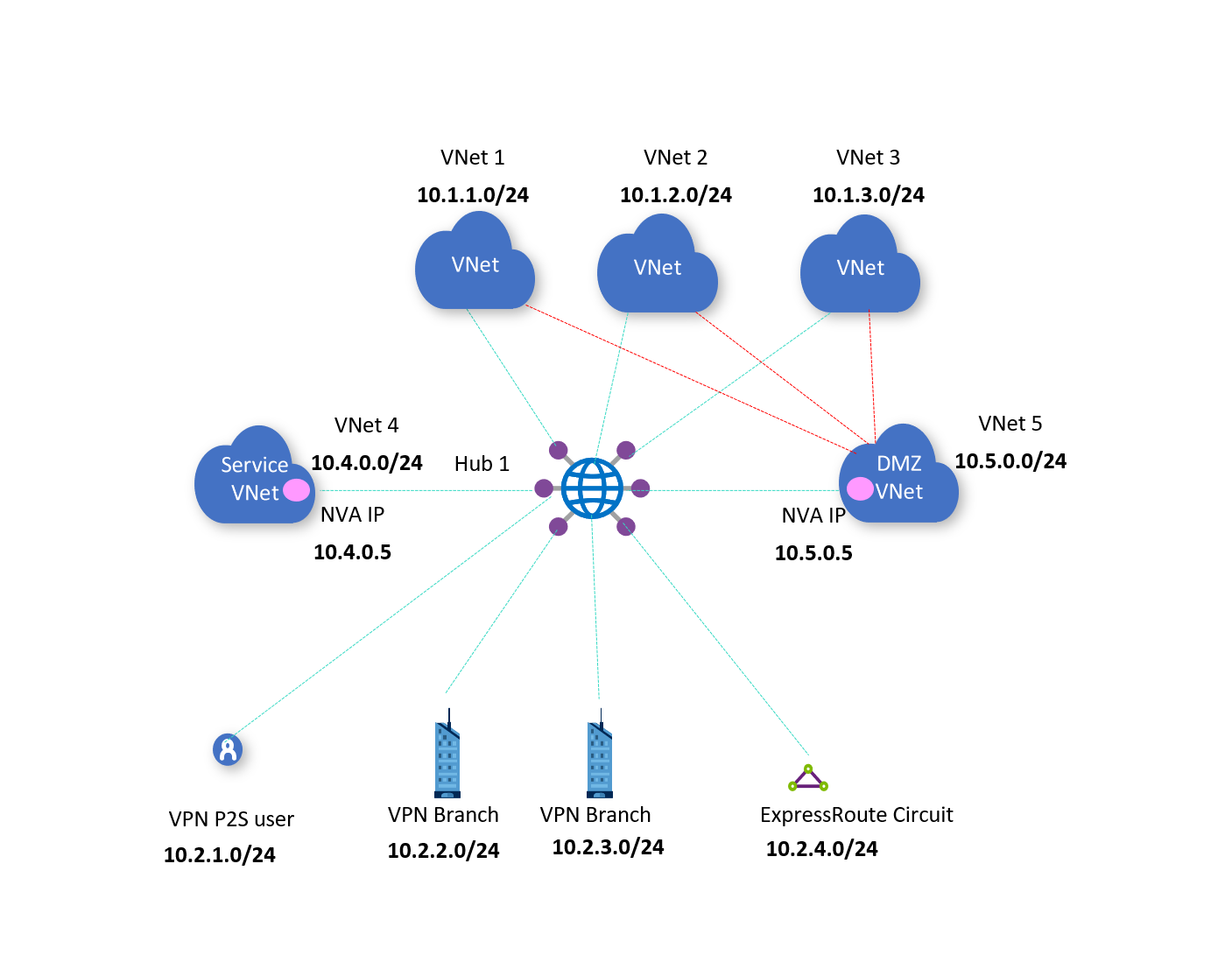
The following diagram shows the architecture described earlier in the article.
In the diagram, there is one hub; Hub 1.
Hub 1 is directly connected to NVA VNets VNet 4 and VNet 5.
Traffic between VNets 1, 2, 3 and the branches is expected to go via VNet 4 NVA 10.4.0.5.
All internet bound traffic from VNets 1, 2, and 3 is expected to go via VNet 5 NVA 10.5.0.5.
Workflow
To set up routing via NVA, consider the following steps:
For internet-bound traffic to go via VNet 5, you need VNets 1, 2, and 3 to directly connect via virtual network peering to VNet 5. You also need a user-defined route set up in the virtual networks for 0.0.0.0/0 and next hop 10.5.0.5.
If you do not want to connect VNets 1, 2, and 3 to VNet 5 and instead just use the NVA in VNet 4 to route 0.0.0.0/0 traffic from branches (on-premises VPN or ExpressRoute connections), go to the alternate workflow.
However, if you want VNet-to-VNet traffic to transit through the NVA, you would need to disconnect VNet 1,2,3 from the virtual hub and connect it or stack it above the NVA Spoke VNet4. In Virtual WAN, VNet-to-VNet traffic transits through the Virtual WAN hub or a Virtual WAN hub’s Azure Firewall (Secure hub). If VNets peer directly using VNet peering, then they can communicate directly bypassing the transit through the virtual hub.
In the Azure portal, go to your virtual hub and create a custom route table called RT_Shared. This table learns routes via propagation from all virtual networks and branch connections. You can see this empty table in the following diagram.
Routes: You don't need to add any static routes.
Association: Select VNets 4 and 5, which means that the connections of these virtual networks associate to the route table RT_Shared.
Propagation: Because you want all branches and virtual network connections to propagate their routes dynamically to this route table, select branches and all virtual networks.
Create a custom route table called RT_V2B for directing traffic from VNets 1, 2, and 3 to branches.
Routes: Add an aggregated static route entry for branches, with next hop as the VNet 4 connection. Configure a static route in VNet 4’s connection for branch prefixes. Indicate the next hop as the specific IP of the NVA in VNet 4.
Association: Select all VNets 1, 2, and 3. This implies that VNet connections 1, 2, and 3 will associate to this route table and be able to learn routes (static and dynamic via propagation) in this route table.
Propagation: Connections propagate routes to route tables. Selecting VNets 1, 2, and 3 enables propagating routes from VNets 1, 2, and 3 to this route table. There's no need to propagate routes from branch connections to RT_V2B, because branch virtual network traffic goes via the NVA in VNet 4.
Edit the default route table, DefaultRouteTable.
All VPN, Azure ExpressRoute, and user VPN connections are associated to the default route table. All VPN, ExpressRoute, and user VPN connections propagate routes to the same set of route tables.
Routes: Add an aggregated static route entry for VNets 1, 2, and 3, with next hop as the VNet 4 connection. Configure a static route in VNet 4’s connection for VNet 1, 2, and 3 aggregated prefixes. Indicate the next hop as the specific IP of the NVA in VNet 4.
Association: Make sure the option for branches (VPN/ER/P2S) is selected, ensuring that on-premises branch connections are associated to the default route table.
Propagation from: Make sure the option for branches (VPN/ER/P2S) is selected, ensuring that on-premises connections are propagating routes to the default route table.
Alternate workflow
In this workflow, you don't connect VNets 1, 2, and 3 to VNet 5. Instead, you use the NVA in VNet 4 to route 0.0.0.0/0 traffic from branches (on-premises VPN or ExpressRoute connections).
To set up routing via NVA, consider the following steps:
In the Azure portal, go to your virtual hub and create a custom route table called RT_NVA for directing traffic via the NVA 10.4.0.5
Routes: No action required.
Association: Select VNet4. This implies that VNet connection 4 will associate to this route table and is able to learn routes (static and dynamic via propagation) in this route table.
Propagation: Connections propagate routes to route tables. Selecting VNets 1, 2, and 3 enables propagating routes from VNets 1, 2, and 3 to this route table. Selecting branches (VPN/ER/P2S) enables propagating routes from branches/on-premises connections to this route table. All VPN, ExpressRoute, and user VPN connections propagate routes to the same set of route tables.
Create a custom route table called RT_VNET for directing traffic from VNets 1, 2, and 3 to branches or the internet (0.0.0.0/0) via the VNet4 NVA. VNet-to-VNet traffic will be direct, and not through VNet 4’s NVA. If you want traffic to go via the NVA, disconnect VNet 1, 2, and 3 and connect them using VNet peering to VNet4.
Routes:
Add an aggregated route '10.2.0.0/16' with next hop as the VNet 4 connection for traffic going from VNets 1, 2, and 3 towards branches. In the VNet4 connection, configure a route for '10.2.0.0/16' and indicate the next hop to be the specific IP of the NVA in VNet 4.
Add a route '0.0.0.0/0' with next hop as the VNet 4 connection. '0.0.0.0/0' is added to imply sending traffic to internet. It does not imply specific address prefixes pertaining to VNets or branches. In the VNet4 connection, configure a route for '0.0.0.0/0', and indicate the next hop to be the specific IP of the NVA in VNet 4.
Association: Select all VNets 1, 2, and 3. This implies that VNet connections 1, 2, and 3 will associate to this route table and be able to learn routes (static and dynamic via propagation) in this route table.
Propagation: Connections propagate routes to route tables. Selecting VNets 1, 2, and 3 enables propagating routes from VNets 1, 2, and 3 to this route table. Make sure the option for branches (VPN/ER/P2S) is not selected. This ensures that on-premises connections cannot get to the VNets 1, 2, and 3 directly.
Edit the default route table, DefaultRouteTable.
All VPN, Azure ExpressRoute, and user VPN connections are associated to the default route table. All VPN, ExpressRoute, and user VPN connections propagate routes to the same set of route tables.
Routes:
Add an aggregated route '10.1.0.0/16' for VNets 1, 2, and 3 with next hop as the VNet 4 connection.
Add a route '0.0.0.0/0' with next hop as the VNet 4 connection. '0.0.0.0/0' is added to imply sending traffic to internet. It does not imply specific address prefixes pertaining to VNets or branches. In the prior step for the VNet4 connection, you would already have configured a route for '0.0.0.0/0', with next hop to be the specific IP of the NVA in VNet 4.
Association: Make sure the option for branches (VPN/ER/P2S) is selected. This ensures that on-premises branch connections are associated to the default route table. All VPN, Azure ExpressRoute, and user VPN connections are associated only to the default route table.
Propagation from: Make sure the option for branches (VPN/ER/P2S) is selected. This ensures that on-premises connections are propagating routes to the default route table. All VPN, ExpressRoute, and user VPN connections propagate routes to the 'same set of route tables'.
Considerations
Portal users must enable 'Propagate to default route' on connections (VPN/ER/P2S/VNet) for the 0.0.0.0/0 route to take effect.
PS/CLI/REST users must set flag 'enableinternetsecurity' to true for the 0.0.0.0/0 route to take effect.
Virtual network connection does not support 'multiple/unique' next hop IP to the 'same' network virtual appliance in a spoke VNet 'if' one of the routes with next hop IP is indicated to be public IP address or 0.0.0.0/0 (internet).
When 0.0.0.0/0 is configured as a static route on a virtual network connection, that route is applied to all traffic, including the resources within the spoke itself. This means all traffic will be forwarded to the next hop IP address of the static route (NVA Private IP). Thus, in deployments with a 0.0.0.0/0 route with next hop NVA IP address configured on a spoke virtual network connection, to access workloads in the same virtual network as the NVA directly (i.e. so that traffic does not pass through the NVA), specify a /32 route on the spoke virtual network connection. For instance, if you want to access 10.1.3.1 directly, specify 10.1.3.1/32 next hop 10.1.3.1 on the spoke virtual network connection.
To simplify routing and to reduce the changes in the Virtual WAN hub route tables, we encourage using the new "BGP peering with Virtual WAN hub" option.