Blend modes
 Browse the sample
.NET Multi-platform App UI (.NET MAUI) graphics enables different compositing operations for graphical objects to be specified by the ICanvas.BlendMode property. This property determines what happens when a graphical object (called the source), is rendered on top of an existing graphical object (called the destination).
Important
Blend modes are only implemented on iOS and Mac Catalyst. For more information, see this GitHub issue.
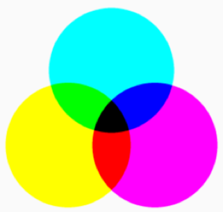
By default, the last drawn object obscures the objects drawn underneath it:
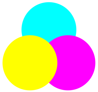
In this example, the cyan circle is drawn first, followed by the magenta circle, then the yellow circle. Each circle obscures the circle drawn underneath it. This occurs because the default blend mode is Normal, which means that the source is drawn over the destination. However, it's possible to specify a different blend mode for a different result. For example, if you specify DestinationOver, then in the area where the source and destination intersect, the destination is drawn over the source.
The 28 members of the BlendMode enumeration can be divided into three categories:
| Separable | Non-Separable | Porter-Duff |
|---|---|---|
Normal |
Hue |
Clear |
Multiply |
Saturation |
Copy |
Screen |
Color |
SourceIn |
Overlay |
Luminosity |
SourceOut |
Darken |
SourceAtop |
|
Lighten |
DestinationOver |
|
ColorDodge |
DestinationIn |
|
ColorBurn |
DestinationOut |
|
SoftLight |
DestinationAtop |
|
HardLight |
Xor |
|
Difference |
PlusDarker |
|
Exclusion |
PlusLighter |
The order that the members are listed in the table above is the same as in the BlendMode enumeration. The first column lists the 12 separable blend modes, while the second column lists the non-separable blend modes. Finally, the third column lists the Porter-Duff blend modes.
Porter-Duff blend modes
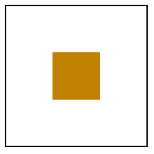
The Porter-Duff blend modes, named after Thomas Porter and Tom Duff, define 12 compositing operators that describe how to compute the color resulting from the composition of the source with the destination. These compositing operators can best be described by considering the case of drawing two rectangles that contain transparent areas:
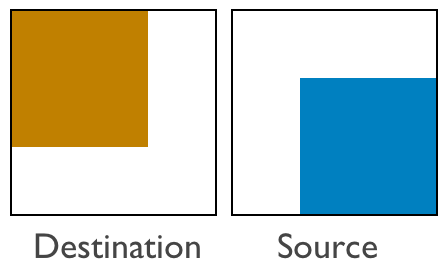
In the image above, the destination is a transparent rectangle except for a brown area that occupies the left and top two-thirds of the display surface. The source is also a transparent rectangle except for a blue area that occupies the right and bottom two-thirds of the display surface. Displaying the source on the destination produces the following result:
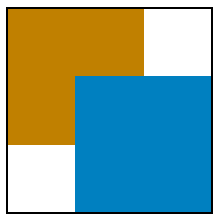
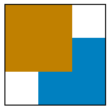
The transparent pixels of the source allow the background to show through, while the blue source pixels obscure the background. This is the normal case, using the default blend mode of Normal. However, it's possible to specify that in the area where the source and destination intersect, the destination appears instead of the source, using the DestinationOver blend mode:
The DestinationIn blend mode displays only the area where the destination and source intersect, using the destination color:
The Xor blend mode causes nothing to appear where the two areas overlap:

The colored destination and source rectangles effectively divide the display surface into four unique areas that can be colored in different ways, corresponding to the presence of the destination and source rectangles:
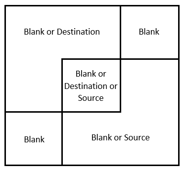
The upper-right and lower-left rectangles are always blank because both the destination and source are transparent in those areas. The destination color occupies the upper-left area, so that area can either be colored with the destination color or not at all. Similarly, the source color occupies the lower-right area, so that area can be colored with the source color or not at all.
The following table lists the Porter-Duff blend modes provided by Microsoft.Maui.Graphics, and how they color each of the three non-blank areas in the diagram above:
| Blend mode | Destination | Intersection | Source |
|---|---|---|---|
Clear |
|||
Copy |
Source | X | |
SourceIn |
Source | ||
SourceOut |
X | ||
SourceAtop |
X | Source | |
DestinationOver |
X | Destination | X |
DestinationIn |
Destination | ||
DestinationOut |
X | ||
DestinationAtop |
Destination | X | |
Xor |
X | X | |
PlusDarker |
X | Sum | X |
PlusLighter |
X | Sum | X |
The naming convention of the modes follows a few simple rules:
- The Over suffix indicates what is visible in the intersection. Either the source or destination is drawn over the other.
- The In suffix means that only the intersection is colored. The output is restricted to only the part of the source or destination that is in the other.
- The Out suffix means that the intersection isn't colored. The output is only the part of the source or destination that is out of the intersection.
- The Atop suffix is the union of In and Out. It includes the area where the source or destination is atop of the other.
Note
These blend modes are symmetrical. The source and destination can be exchanged, and all the modes are still available.
The PlusLighter blend mode sums the source and destination. Then, for values above 1, white is displayed. Similarly, the PlusDarker blend mode sums the source and destination, but subtracts 1 from the resulting values, with values below 0 becoming black.
Separable blend modes
The separable blend modes alter the individual red, green, and blue color components of a graphical object.
The following table shows the separable blend modes, with brief explanations of what they do. In the table, Dc and Sc refer to the destination and source colors, and the second column shows the source color that produces no change:
| Blend mode | No change | Operation |
|---|---|---|
Normal |
No blending, source selected | |
Multiply |
White |
Darkens by multiplying Sc-Dc |
Screen |
Black |
Complements the product of complements: Sc + Dc - Sc.Dc |
Overlay |
Gray |
Inverse of HardLight |
Darken |
White |
Minimum of colors: min(Sc, Dc) |
Lighten |
Black |
Maximum of colors: max(Sc, Dc) |
ColorDodge |
Black |
Brightens the destination based on the source |
ColorBurn |
White |
Darkens the destination based on the source |
SoftLight |
Gray |
Similar to the effect of a soft spotlight |
HardLight |
Gray |
Similar to the effect of a harsh spotlight |
Difference |
Black |
Subtracts the darker color from the lighter color: Abs(Dc - Sc) |
Exclusion |
Black |
Similar to Difference but lower contrast |
Note
If the source is transparent, then the separable blend modes have no effect.
The following example uses the Multiply blend mode to draw three overlapping circles of cyan, magenta, and yellow:
PointF center = new PointF(dirtyRect.Center.X, dirtyRect.Center.Y);
float radius = Math.Min(dirtyRect.Width, dirtyRect.Height) / 4;
float distance = 0.8f * radius;

PointF center1 = new PointF(distance * (float)Math.Cos(9 * Math.PI / 6) + center.X,
    distance * (float)Math.Sin(9 * Math.PI / 6) + center.Y);
PointF center2 = new PointF(distance * (float)Math.Cos(1 * Math.PI / 6) + center.X,
    distance * (float)Math.Sin(1 * Math.PI / 6) + center.Y);
PointF center3 = new PointF(distance * (float)Math.Cos(5 * Math.PI / 6) + center.X,
    distance * (float)Math.Sin(5 * Math.PI / 6) + center.Y);

canvas.BlendMode = BlendMode.Multiply;

canvas.FillColor = Colors.Cyan;
canvas.FillCircle(center1, radius);

canvas.FillColor = Colors.Magenta;
canvas.FillCircle(center2, radius);

canvas.FillColor = Colors.Yellow;
canvas.FillCircle(center3, radius);
The result is that a combination of any two colors produces red, green, and blue, and a combination of all three colors produces black.
Non-separable blend modes
The non-separable blend modes combine hue, saturation, and luminosity values from the destination and the source. Understanding these blend modes requires an understanding of the Hue-Saturation-Luminosity (HSL) color model:
- The hue value represents the dominant wavelength of the color. Hue values range from 0 to 360, and cycle through the additive and subtractive primary colors. Red is the value 0, yellow is 60, green is 120, cyan is 180, blue is 240, magenta is 300, and the cycle returns to red at 360. If there is no dominant color, for example the color is white or black or a gray shade, then the hue is undefined and usually set to 0.
- The saturation value indicates the purity of the color, and can range from 0 to 100. A saturation value of 100 is the purest color while values lower than 100 cause the color to become more grayish. A saturation value of 0 results in a shade of gray.
- The luminosity value indicates how bright the color is. A luminosity value of 0 is black regardless of other values. Similarly, a luminosity value of 100 is white.
The HSL value (0,100,50) is the RGB value (255,0,0), which is pure red. The HSL value (180,100,50) is the RGB value (0, 255, 255), which is pure cyan. As the saturation is decreased, the dominant color component is decreased and the other components are increased. At a saturation level of 0, all the components are the same and color is a gray shade.
The non-separable blend modes conceptually perform the following steps:
- Convert the source and destination objects from their original color space to the HSL color space.
- Create the composited object from a combination of hue, saturation, and luminosity components, from the source and destination objects.
- Convert the result back to the original color space.
The following table lists how which HSL components are composited for each non-separable blend mode:
| Blend mode | Source components | Destination components |
|---|---|---|
Hue |
Hue | Saturation and Luminosity |
Saturation |
Saturation | Hue and Luminosity |
Color |
Hue and Saturation | Luminosity |
Luminosity |
Luminosity | Hue and Saturation |
Feedback
Coming soon: Throughout 2024 we will be phasing out GitHub Issues as the feedback mechanism for content and replacing it with a new feedback system. For more information see: https://aka.ms/ContentUserFeedback.
Submit and view feedback for