Note
Access to this page requires authorization. You can try signing in or changing directories.
Access to this page requires authorization. You can try changing directories.
This article describes, in detail, how the Phantom line type can be used for the lines of a bill of materials (BOM) and a formula.
In figure 1, (a) is the BOM for product H and parts F and G, and (b) is the route sheet for products H and part F.
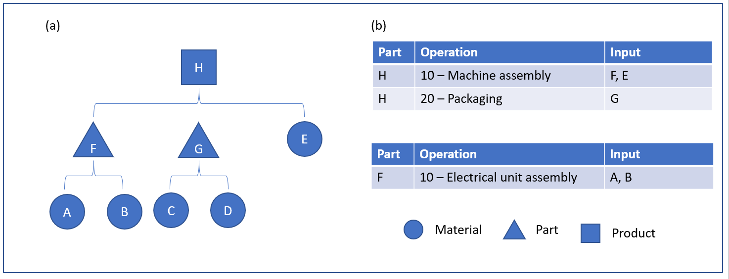 Figure 1: Engineering BOM
Figure 1 shows an example of a BOM structure in two levels. Finished product H represents a product for a machine assembly. The machine assembly consists of two parts, an electrical unit (F) that has two materials (A and B) and a group of packaging materials (G) that also has two materials (C and D). Another material (E) is used during the general assembly of the machine.
Figure 1 represents the Engineering BOM for product H. This structure provides a good overview of the parts and components of the overall machine assembly. However, although product designers might prefer to see the BOM represented in this way, this structure might not correctly represent the way that the machine is built on the shop floor.
For example, the Engineering BOM in the figure 1 indicates that electrical unit F is assembled as a separate part on a separate work order. However, on the shop floor, it might be judged more optimal to assemble the electrical unit as part of the overall machine assembly, not as a separate work order.
This Engineering BOM also indicates that part G is a separate part. However, in this structure, part G doesn’t represent a physical part but a collection of packaging materials.
Therefore, although an Engineering BOM provides great value for the design of a product and maintenance of that design, it might not be the most logical way to support the manufacturing execution process of the product. By contrast, a Manufacturing BOM represents the best way to build a product.
Figure 2 shows how the preceding Engineering BOM is transitioned into a Manufacturing BOM. In figure 2, (a) is the BOM for product H, and b is the route sheet for product H.
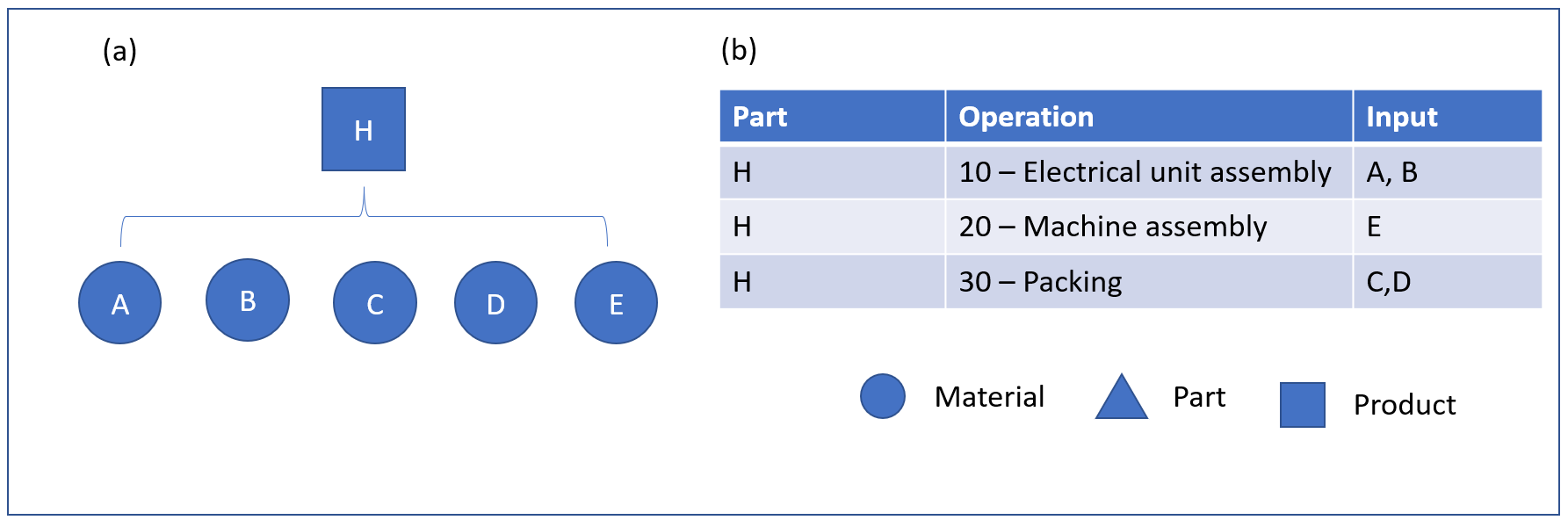 Figure 2: Manufacturing BOM
In this structure, you can see that there's no notion of parts F and G, and the materials that these parts consist of have been elevated to the next BOM level.
Unlike the Engineering BOM, which had two operations sheets, the Manufacturing BOM has only one operations sheet. The packaging operation that was linked to part G has also been elevated and is now part of the operations sheet for product H. The assembly of the electrical unit is the first operation. This order makes good sense, because this unit is used in the next operation, which is the machine assembly. The last operation is the packaging operation, which consumes two packing materials (C and D).
The transition between the Engineering BOM and the Manufacturing BOM is enabled through the Phantom BOM line type. As the term phantom indicates, parts F and G have disappeared during the transition between the two BOM types. In this example, the Phantom line type is applied to the BOM lines for parts F and G in the Engineering BOM. When a production or batch order is created, the Engineering BOM is copied to the production or batch order. Then, when the order is estimated, the transition from the Engineering BOM to the Manufacturing BOM occurs, as shown in figure 2. From the operations sheet in figure 2, packaging materials C and D are input for the operation.
Multilevel phantom BOM structures
The Phantom line type can be used in multilevel BOM structures, as shown in figure 3. In figure 3, (a) is the BOM for product G, and (b) is the route sheet for parts E and F and product G.
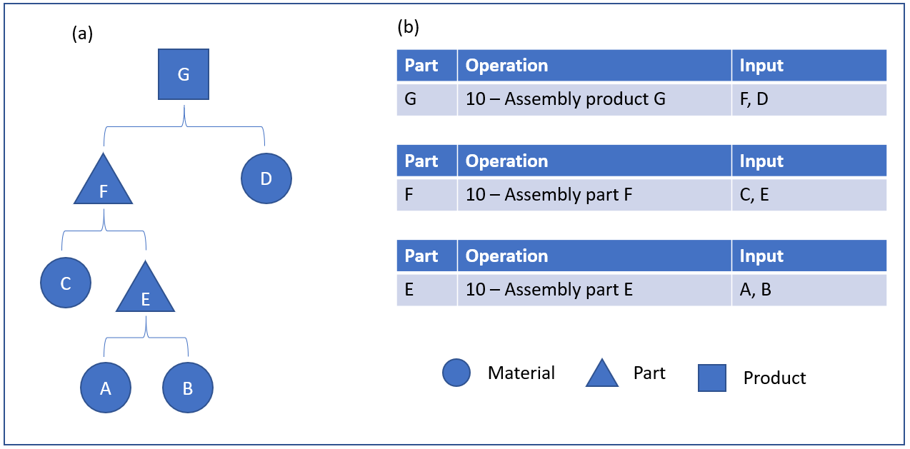 Figure 3: Engineering BOM part G
Figure 4 shows the resulting Manufacturing BOM and route sheet if the BOM lines for parts E and F are configured so that the line type is Phantom. In figure 4, (a) is the BOM for product G, and (b) is the route sheet for product G.
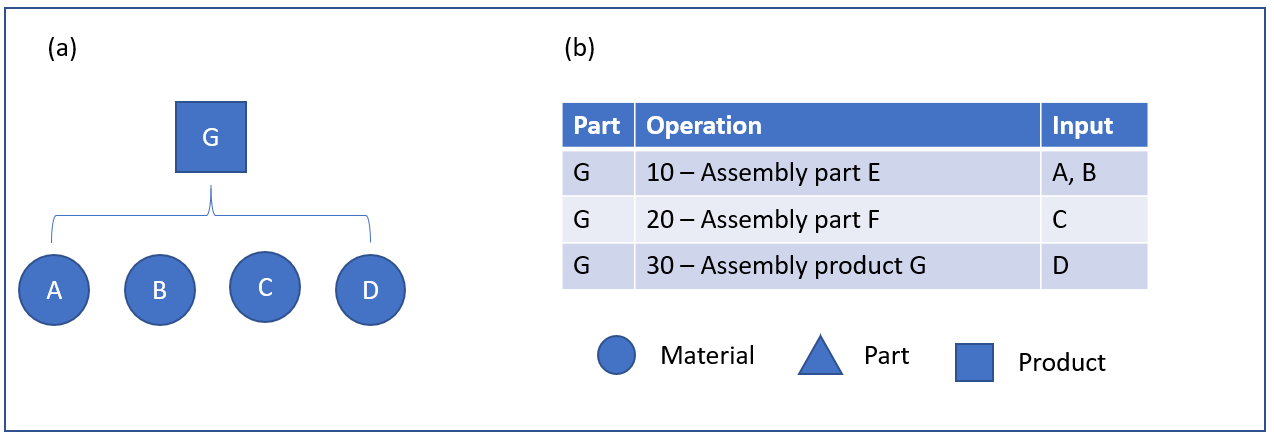 Figure 4: Manufacturing BOM part G
Phantom and route network
Phantom BOMs can also be used for a BOM that has a route network. In a route network, one or more operations run in parallel. Figure 5 shows an example of a route network that is used in a multilevel BOM. In figure 5, (a) is the BOM for product G and part F, and (b) is the route sheet for product G and part F, which has a route network.
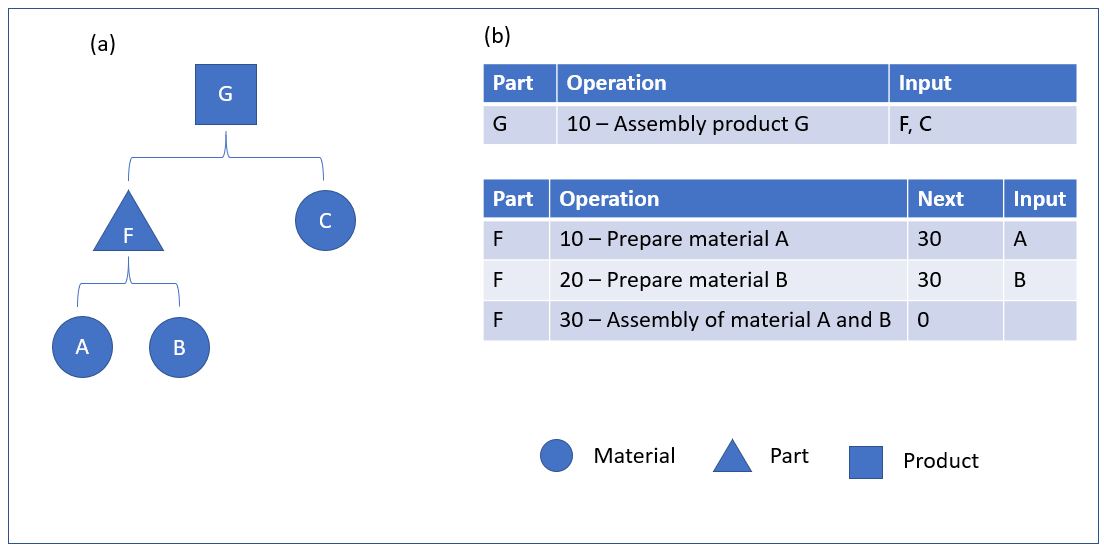 Figure 5: Engineering BOM part G, route network
In figure 6, (a) is the BOM for product G and part F, and (b) is the route sheet for product G and part F.
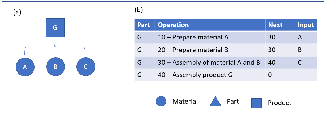 Figure 6: Manufacturing BOM part G, route network