Using the Microsoft Deployment Toolkit
Microsoft® Deployment Toolkit (MDT) 2013 allows you to automate the deployment of computers in your organization. This document provides guidance on how to plan, build, and deploy Windows® operating systems and applications using MDT 2013.
Note
In this document, Windows applies to the Windows 8.1, Windows 8, Windows 7, Windows Server® 2012 R2, Windows Server 2012, and Windows Server 2008 R2 unless otherwise noted. MDT does not support ARM processor-based versions of Windows. Similarly, MDT refers to MDT 2013 unless otherwise stated.
MDT performs deployments by using the Lite Touch Installation (LTI), Zero Touch Installation (ZTI), and User-Driven Installation (UDI) deployment methods. Only MDT is used in LTI deployments, while ZTI and UDI deployments are performed using MDT with Microsoft System Center 2012 R2 Configuration Manager.
This document covers these deployment methods and shows how to customize the deployment process for an organization. In addition to this document, Table 1 lists other documents that will help you perform deployments using MDT in your organization.
Table 1. Additional MDT Documents for Use in the Deployment Process
| Document | Description |
|---|---|
| Microsoft Deployment Toolkit Samples Guide | Provides scenario-based samples of how to solve common deployment issues using MDT. Most samples include example configuration files and step-by-step processes for implementing the solution. Use this document to help solve difficult deployment problems. |
| Toolkit Reference | Provides information about the task sequence steps, properties, support files, utilities, and databases used in MDT deployments. Use this document to help customize MDT deployments for your organization. |
| Troubleshooting Reference | Provides information to assist in troubleshooting common problems with MDT deployments, including lists of known issues, reviewing logs, and identifying issues by error code. |
This document is organized to help you through the planning, building, and deploying processes in your organization. The following sections in this guide help you perform LTI, ZTI, and UDI deployments and customize the deployment process. Table 2 lists each section in this guide, with a brief overview of each.
Table 2. Sections in This Document
| Section | Overview |
|---|---|
| Planning MDT Deployments | Provides guidance for completing the planning tasks in preparation for MDT deployments. Review this section to help identify prerequisites, perform capacity planning, and perform any infrastructure remediation prior to deployment in a production environment, and learn how to install MDT in the environment. |
| Installing or Upgrading to MDT | Provides guidance for performing a new installation of MDT or upgrading to MDT from previous versions of MDT. |
| Performing LTI Deployments | Provides guidance for deploying Windows operating systems and applications using only MDT. The guidance presented in this section starts immediately after the installation of MDT and provides the steps for creating a reference computer, capturing an image of the reference computer, and then deploying the captured image to target computers in the organization. |
| Managing LTI Deployments in the Deployment Workbench | Provides guidance and step-by-step instructions for managing LTI deployments using the Deployment Workbench, including managing operating systems, device drivers, applications, the MDT database (MDT DB), and other deployment elements in the Deployment Workbench. |
| Running the Deployment Wizard | Provides guidance of how to run the Deployment Wizard to deploy operating systems, device drivers, and applications to the target computers in your organization. |
| Performing ZTI Deployments Using Configuration Manager | Provides guidance for deploying Windows operating systems and applications using MDT and Configuration Manager. The guidance presented in this section starts immediately after the installation of MDT and provides the steps for creating a reference computer, capturing an image of the reference computer, and then deploying the captured image to target computers in the organization using Configuration Manager. |
| Managing ZTI Deployments in the Configuration Manager Console in Configuration Manager | Provides guidance and step-by-step instructions for managing ZTI deployments using the Configuration Manager console in Configuration Manager, including managing operating systems, device drivers, applications, and other deployment elements. |
| Performing UDI Deployments | Provides guidance for deploying Windows operating systems and applications using MDT, Configuration Manager, and the UDI Wizard. The guidance presented in this section starts immediately after the installation of MDT and provides the steps for creating a reference computer, capturing an image of the reference computer, and then deploying the captured image to target computers in the organization using the Configuration Manager console and the UDI Wizard. |
| Managing UDI Deployments | Provides guidance and step-by-step instructions for managing UDI deployments using the Configuration Manager console, the UDI Wizard Designer, and the UDI Wizard, including: - Managing operating systems, device drivers, applications, and other deployment elements in the Configuration Manager console. Most of the deployment process and step-by-step instructions for ZTI are applicable to UDI. - Managing the behavior of the UDI Wizard. |
| Running the UDI Wizard | Provides guidance of how to run the UDI Wizard to deploy operating systems, device drivers, and applications to the target computers in your organization. |
| Configuring MDT Deployments | Provides guidance on how to customize the process for more advanced deployment scenarios, including a discussion of the MDT configuration files, how to apply configuration settings to groups of computers, and how to apply configuration settings to individual computers. |
| Performing Deployments Using the MDT DB | Provides guidance on customizing the process for more advanced deployment scenarios, including how to add entries to and retrieve configuration settings from the MDT DB. |
| Preparing the MDT Migration Resources | Provides guidance on preparing the appropriate resources used in the MDT deployment process, including network shared folders and database access. |
| Preparing Windows Deployment Services | Provides guidance on preparing Windows Deployment Services for use in initiating the LTI, ZTI, and UDI deployment processes, including creating images and configuring for integration with LTI, ZTI, and UDI deployments. |
| Planning for Application Deployment | Provides guidance on how to deploy applications by using MDT, Configuration Manager, and Microsoft Application Virtualization (App-V), including deployment of applications with the operating system image or after the image is deployed. |
Planning MDT Deployments
The planning process helps you prepare for deployments in a production environment. The process starts with conceptual designs, which are proven and refined in a test environment. The result of the planning process is a set of design documents that you can use to build an MDT deployment infrastructure and perform automated operating system and application deployments in a production environment.
Overview of the MDT Deployment Process
The purpose of MDT is to help automate the deployment of Windows operating systems and applications to desktop, portable, and server computers in the environment. At a high level, MDT automates the deployment process by configuring the unattended Setup files for Windows and packaging the necessary files into a consolidated image file that you then deploy to reference and target computers.
Figure 1 illustrates the high-level LTI, ZTI, and UDI deployment processes.
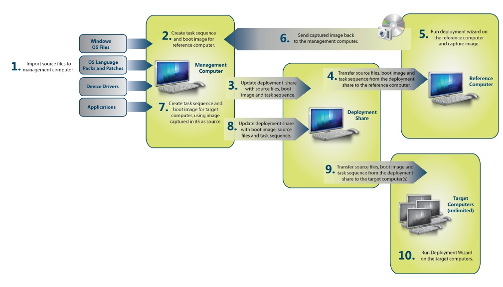
Figure 1. High-level deployment process
The high-level LTI, ZTI, and UDI deployment process is as follows:
Collect the files necessary to perform an MDT deployment, including:
Windows operating system source files or images
Windows operating system language packs
Device drivers for reference and target computers
Create the system images, configuration settings, and task sequences to be used in deploying Windows and applications to the reference computers.
Deploy the system images to the reference computer and capture an image of the reference computer.
Create the configuration settings and task sequences that will deploy the captured images of the reference computers to the target computers.
Deploy the captured images of the reference computers to the target computers.
Planning Checklist
Table 3 provides a planning checklist in the form of a list of questions that you can use to help in the planning process. For each question, use the information provided in the Overview column to help find answers based on your organization's requirements.
Table 3. Planning Checklist
| Question | Overview |
|---|---|
| Where will you store your distribution files? | Files for the operating system and applications are stored in deployment shares for LTI and distribution points for ZTI and UDI. These files can require many gigabytes of space. Some organizations might need multiple deployment shares or distribution points for different regional offices.For more information, see Estimating MDT Storage Requirements. |
| Will you deploy across the network, with removable media, or both? Will you use multicast deployments? | If you are deploying across the network, verify that there is sufficient bandwidth between the deployment shares, distribution points, and the target computers, and provide regional distribution points.For more information, see Choosing a Deployment Method and Evaluating Network Requirements. |
| What is your imaging and source file strategy? | For more information, see Using Reference Computers in MDT Deployments. |
| Will you deploy a full set of operating system files or a custom image? | For more information, see Using Reference Computers in MDT Deployments. |
| How will you handle product keys and licensing? | Small organizations might assign each user an individual product key. Larger organizations should use Key Management Service (KMS) or Multiple Activation Key (MAK) activation. For more information, see Product Activation and Key Information. |
| Are you going to allow users to choose their own operating system, applications, locale, time zone, and administrative password? | Users can select this information at deployment time, or you can configure the information ahead of time. For more information, see Choosing LTI, ZTI, or UDI Deployments. |
| Will users refresh their current computer in place, migrate settings to a new operating system installation, or get a new computer? | For more information, see Identifying Deployment Scenarios. |
| Which users will be able to install which applications? | For more information, see Planning for Application Deployment. |
| Are you going to migrate user state? | For more information, see Estimate Storage Requirements for User State Migration Data. |
| Do you want to back up computers before deployment? | For more information, see Estimate Storage Requirements for Target Computer Backup. |
| Do you want to use BitLocker® Drive Encryption? | For more information, see Planning for BitLocker Drive Encryption. |
| Will you deploy 32-bit and 64-bit operating systems? | For more information, see Estimating MDT Storage Requirements. |
| Will you deploy different product editions (such as Professional, Ultimate, or Business)? | For more information, see Estimating MDT Storage Requirements. |
| What type of deployments will be performed (for example, deploy a new computer, replace an existing computer)? | For more information, see Identifying Deployment Scenarios. |
Estimating MDT Storage Requirements
LTI deployments store the system images, applications, and other files in deployment shares. ZTI and UDI deployments store these files on Configuration Manager distribution points. To determine your storage needs, estimate storage requirements for:
Computers running MDT as described in Estimate Storage Requirements for Computers Running MDT
Each MDT deployment share as described in Estimate Storage Requirements for MDT Deployment Shares
Each Configuration Manager distribution point as described in Estimate Storage Requirements for Configuration Manager Distribution Points
User state migration data as described in Estimate Storage Requirements for User State Migration Data
Backing up existing computers prior to deployment for Refresh Computer deployment scenario as described in Estimate Storage Requirements for Target Computer Backup
Estimate Storage Requirements for Computers Running MDT
The computer running MDT has the following storage requirements:
At least 4 gigabytes (GB) of free space is required on the drive containing the %TEMP% folder if you will create a media images. Otherwise, 1 GB of free space is required on the drive containing the %TEMP% folder.
Free space of 1 GB is required on the drive containing the MDT program files.
Estimate Storage Requirements for MDT Deployment Shares
Ensure that sufficient space is available for storing the operating system images, language packs, and device drivers used in the Deployment Workbench. You store these images in the MDT deployment shares created in the Deployment Workbench.
Determine the storage requirements for each of the following items in the deployment share:
Windows operating system
Operating system language pack
Device drivers
Applications
Determine the size of each image and the number of images required in the deployment. Create a unique image for each:
Version of the Windows operating system to be deployed. A separate image is required for each version of Windows, such as Windows 8.1, Windows 7, Windows Server 2012 R2, or Windows Server 2008 R2.
Edition of the Windows operating system to be deployed. A separate image is required for each edition of Windows, such as Tablet PC, Ultimate, Business, Enterprise, or Datacenter.
Processor type. A separate image is required for 32-bit and 64-bit versions of Windows.
Estimate Storage Requirements for Configuration Manager Distribution Points
Estimate the storage requirements for Configuration Manager distribution points using the same calculations described in Estimate Storage Requirements for MDT Deployment Shares. If the images are distributed to multiple distribution points, the storage requirements apply to each distribution point.
For more information about planning Configuration Manager distribution points, see the section, "Distribution Point," in the section, "Planning Configuration Manager Site Systems for Operating System Deployments," in the Configuration Manager Documentation Library, which is installed with Configuration Manager.
Estimate Storage Requirements for User State Migration Data
Estimate the amount of storage required for user state migration data that the Windows User State Migration Tool (USMT) saved during the deployment process by:
Determining whether to store the user state migration data locally on the target computers or network shared folders as described in Determine Where to Store User State Migration Data
Determining the storage requirements for the user state migration data as described in Determine Storage Requirements for User State Migration Data
Determine Where to Store User State Migration Data
After determining the storage requirements for the user state migration data, determine where to store the data. Store user state migration data in these locations:
On the local computer to reduce the time to deploy Windows as well as network utilization (recommended)
Note
This option can be used only in a Refresh Computer scenario.
On a shared folder located on a local server to provide a consistent method of storing user state migration data or when local storage is not available.
If user state migration data will be stored locally on the target computers, designate a shared folder in which the deploy process can store the data. By default, the process attempts to store user state data on the local hard disk for the Replace Computer and Refresh Computer scenarios. However, you can override this behavior with configuration settings in CustomSettings.ini. In the event that there is insufficient disk space for the user state data and new image, the deployment scripts attempt to store the information in a shared folder. Providing the shared folder as an alternate storage location makes the deployment process more reliable.
Create a share on a server designated during the planning process for holding the USMT store files. MDT uses values found in CustomSettings.ini to locate the user state store folder.
Determine Storage Requirements for User State Migration Data
For planning purposes, complete the following tasks to estimate the user state migration storage requirements:
Run Scanstate.exe in the USMT with the /p option to estimate the size of the user state migration data. By using the /p option, you can estimate the disk space requirements without actually performing the migration.
View the size of the contents of the folders in the user profile. Randomly sample targeted computers to determine a typical amount of storage required to back up the user state migration. Keep in mind that there may be several profiles (user name folders) on each target computer, so include each profile to be migrated.
Calculate the total capacity required by multiplying the average size of the user state migration data by the number of days to retain the data, and then multiplying that result by the number of users to be migrated during the retention period. For example, if the average user state migration size is 3 GB, data must be stored for five days, 100 users are being migrated each day, and the total storage requirement is 1,500 GB (3 GB × 5 days × 100 users per day).
Estimate Storage Requirements for Target Computer Backup
As an optional step in the deployment process for the Refresh Computer scenario, you can perform a backup of a target computer before deploying the target operating system.
You perform the backup process in MDT by using the Imagex.exe tool. The backup process creates an image of the disk volume on which the user state migration data is stored. The purpose of this backup is for recovery of user state migration data, not to restore the target computer from the image.
The storage requirements are a function of the average size of the target computer hard disks, the number of target computers deployed each day, and the length of time you want to retain the backup. For example, if the average target computer hard disk contains 80 GB of data, you are deploying 100 computers per day, and you want to retain the data for one week, the storage requirements for backups are 56 terabytes (TB), or 80 GB × 100 × 7.
Note
By default, the MDT backup process does not back up multiple partitions. If you need to back up multiple partitions, modify the MDT deployment process or use an alternative backup method.
Planning for Application Deployment
Applications can be deployed as a part of the operating system image or after the operating system is deployed to the target computer. In preparation for deployment, perform these tasks:
Create an application portfolio. Application portfolios include a list of applications and the compatibility status of each application. You can create this application portfolio by using software-inventory software such as the Application Compatibility Toolkit (ACT), the Asset and Compliance feature in Configuration Manager.
Identify any dependencies between applications. Applications may have dependencies on other applications. For example, an application may rely on Microsoft Office Excel® 2007. Identify these dependencies, and include the dependent software in the deployment plans.
Determine whether to deploy applications with the operating system image or afterwards. You can deploy applications as part of the operating system image or after the operating system is deployed to the target computer. If the application is deployed after the operating system is deployed, you can use any software-deployment software, such as MDT, Group Policy Software Installation, the Application Management feature in Configuration Manager.
Determine the appropriate method for running applications. You can install and run applications on the local computer or deploy them dynamically in a virtualized application environment, such as App-V.
Identify the users approved to install applications. Determine whether users will install their applications or if the applications need to be installed by deployment technicians. Ensure that the user installing the application has the appropriate rights and permissions.
Identify applications that require a restart of the operating system. Applications that require a restart of the operating system after installation require additional configuration. For more information, see Configure the Computer to Restart After Application Installation.
Defining Operating System Components and Settings
As part of establishing a standardized configuration, determine which operating system components to include and the settings for these components. This determination includes optional components in all operating systems, server roles in Windows Server operating systems, and components to include in Windows Preinstallation Environment (Windows PE). For example, you may decide to remove unnecessary Windows operating system components from desktop and portable computer deployments to reduce the security footprint of those computers.
For each operating system image, determine the:
**Operating system components.**Select the components required for the applications and user roles performed on the target computers. Install only the components that are required to help reduce the attack surface of the target computer and the image size.
Server roles. Select the server roles required for the server computers. Install only the server roles that are required to help reduce the attack surface of the target computer and the image size.
Windows PE components. These components include Microsoft ActiveX® Data Objects (ADO) support, fonts, and the necessary drivers and packages. You can select the components for 32-bit and 64-bit versions of Windows PE.
Configuration settings. Identify the configuration settings for components included in the images. Select configuration settings that meet the business and security requirements of the organization. For more information about target computer security, see Planning Target Computer Security.
Choosing a Deployment Method
Typically, target computers have high-speed, persistent connections to the deployment infrastructure. However, some target computers may connect to an intranet remotely or not at all. MDT includes the following methods for deploying operating systems and applications using LTI based on the network connectivity:
Deployment share. This method uses a network shared folder in which all the deployment files reside. The target computer starts Windows PE, and then connects to the deployment share to perform the deployment. Select this method when the target computers have high-speed, persistent connections to the deployment infrastructure.
Media. This method creates an image that you can use to perform deployments from removable media, such as DVDs or USB flash drives (UFDs). You use Windows PE to start the computer from the media. Select this method when the target computers may be remotely connected or may not have connectivity at all.
Evaluating Network Requirements
Because of the size of the images being distributed to the target computers (500 megabytes [MB] to 4 GB), computers must have a high-speed, persistent connection to the servers used in the deployment process. These servers need to be on adjacent subnets to the target computers to ensure high-speed connectivity to the computers.
Note
Network-based deployments using MDT are not supported for wireless networks. Use media-based deployments for computers connected by wireless networks or networks with slow or unreliable connectivity.
If the organization cannot provide sufficient network capacity to deploy images, software, and migration data to computers, perform one of the following actions:
Temporarily place the appropriate servers (for example, servers hosting the various shared folders or the server running Windows Deployment Services) closer to the target computers for the duration of the migration.
Temporarily move the target computers to a staging area where the computers can be deployed, and then return them to their original location.
Store user state migration data locally on the target computers.
Perform automated deployments locally using media deployments in LTI.
In addition to network capacity, you must enable the appropriate network protocols and traffic. For example, if you want to initiate LTI, ZTI, or UDI deployment using Windows Deployment Services and multicast deployment, you must enable multicast traffic between the MDT infrastructure and target computers.
Using Reference Computers in MDT Deployments
The MDT deployment process uses the reference computer as a baseline for the configuration of target computers when the deployment process is complete. You configure the reference computer to comply with the business, technical, and security requirements of the organization. After configuring the reference computer, capture an image of the reference computer that you can then deploy to the target computers.
Only in rare circumstances will you be able to deploy the images from the Windows distribution media unmodified to the reference and target computers. Instead, create customized images that include the Windows operating system, language, packs, applications, device drivers, software updates, and other software.
The MDT deployment process allows for the creation of customized images that are first deployed to a reference computer, then captured from the reference computer, and finally deployed to target computers. MDT manages the customization of images so that you can create them with less effort and higher levels of automation. For example, the Deployment Workbench in MDT can automatically inject the appropriate device drivers into images.
VMs work well when creating a reference image for Windows because the historical HAL issues are no longer applicable.
Note
VMs typically do not have the same performance as physical computers, so creating the reference images may take longer.
Choosing Thick, Thin, or Hybrid Images
As part of the planning process, determine the types of images that you will create. The types of images you can create fall into these categories:
Thick images. Thick images are monolithic images that contain core applications, language packs, and other files. Part of the image-development process is installing core applications and language packs on the reference computer before capturing the disk image.
Thin images. Thin images contain few if any core applications or language packs, as these components are installed separately from the disk image, which typically takes more network transfer time at the computer.
Hybrid images. Hybrid images mix thin and thick image strategies by installing applications and language packs from a network shared folder. Hybrid images have most of the advantages of thin images, but they are not as complex to develop and do not require a software-distribution infrastructure. They do require longer installation times, however, which can raise initial deployment costs.
Table 4 lists the advantages and disadvantages of the thick, thin, and hybrid images types.
Table 4. Advantages and Disadvantages of Thick, Thin, and Hybrid Images
| Method | Advantage | Disadvantage |
|---|---|---|
| Thick | - Can be simpler to deploy, because all applications and language packs are in the image. - Reduced initial complexity, because advanced scripting is not typically required. - Applications and language packs are available immediately after deployment is complete. - Does not require software-distribution software, such as the Application Management feature in Configuration Manager. |
- Requires more storage for each image. - Requires more time to download over network connections than thin or hybrid images. - Requires an increased image maintenance effort, because any updates to operating systems, device drivers, applications, or language packs requires the creation of a new image. |
| Thin | - Requires less storage for each image. - Requires less time than thick images to download over network connections. -Reduced image maintenance effort, because the image contains fewer components. |
- Can be more complex to createinitially, because additional steps are required during image creation. - Potential for increased complexity, because advanced scripting may be required. - Applications and languages are not immediately available after image deployment is complete. |
| Hybrid | - Requires less storage than thick images for each image. - Requires less time to than thick a thick image to download over network connections. - Reduced image maintenance effort, because the image contains fewer components. - Does not require separate software-distribution software. |
- Can be more complex than a thick image (but not than a thin image) to create, because additional steps are required during image creation. - Potential for increased complexity, because advanced scripting (though not as advanced as in thin images) may be required. - pplications and languages are not immediately available after image deployment is complete. |
The costs associated with building, maintaining, and deploying disk images includes:
Development costs. Development costs include creating a well-engineered image to lower future support costs and improve security and reliability. Higher levels of automation reduce development costs.
Test costs. These costs include the time and labor involved in testing the standard image and the applications that might reside inside it in addition to applications applied after deployment. Test costs also include the development time required to stabilize disk images.
Storage costs. Storage costs include storing the distribution points, disk images, migration data, and backup images. Storage costs can be significant depending on the number of disk images, the number of computers in each deployment run, and so on.
Network costs. Network costs include moving disk images to distribution points and to computers. The disk-imaging technologies that Microsoft provides do not support multicasting, so network costs scale linearly with the number of distribution points you must replicate and the number of computers in the deployment project.
As the size of image files increases, costs increase. Large images have more updating, testing, distribution, network, and storage costs associated with them. Even if only a small portion of the image is updated, the entire image must be redistributed.
Identifying Deployment Scenarios
Table 5 lists the deployment scenarios and provides a brief description of each.
Table 5. Deployment Scenarios
| Scenario | Description | Migrates user state | Uses existing target computer | Preserves file system |
|---|---|---|---|---|
| New Computer | A new installation of a Windows operating system is deployed to a new computer. | No | No | No |
| Refresh Computer | A computer is refreshed, including computers that must be re-imaged for image standardization or to address a problem. | Yes | Yes | No |
| Replace Computer | One computer replaces another computer. The existing user state migration data is saved from the original computer. Then, a new installation of Windows is deployed to a new computer. Finally, the user state data is restored to the new computer. | Yes | No | No |
MDT does not support in-place upgrade deployments. You can perform:
An in-place upgrade manually by running Setup.exe from the original Windows media
Note
To perform an in-place upgrade manually by running Setup.exe from the original Windows media, use the original install.wim file. Custom .wim files are not supported for in-place upgrades.
The Refresh Computer scenario as an alternative for deploying a new operating system and applications on the target computer
As part of the Replace Computer deployment scenario, wipe the disk partitions of the original computer. The standard format as performed by Windows operating systems does not perform a secure wipe of the disk as defined by U.S. Department of Defense standard 5520.22M. If required, perform secure wipes of hard disks in target computers using tools provided by non-Microsoft vendors.
Planning for BitLocker Drive Encryption
BitLocker is included in Windows so include planning decisions for BitLocker in your environment. One BitLocker decision you must make is the storage of the recovery keys. You can store BitLocker recovery keys in:
A local folder.Select this option to store the recovery key on UFDs, which each user manages.A network folder. Select this option to centrally store the recovery keys in a network shared folder, which network administrators manage.
Active Directory® Domain Services (AD DS). Select this option to store the recovery keys in AD DS, which Active Directory administrators manage.
Also, elect the methods users will employ to start their computers after BitLocker is enabled. Users can start their computers using one of the following methods:
Trusted Platform Module (TPM) version 1.2 or later. TPM is a cryptographic hardware chip installed on the target computer. If the target computer does not support TPM, a UFD or PIN must be used to start the computer. This is the preferred method if the target computer supports TPM.
Note
You can provide a PIN that users can enter in conjunction with TPM, or you can use a UFD to strengthen the security when starting a computer.
UFD. In this method, the required encryption keys are stored on a UFD, which must be present in the computer when the computer starts. This is the preferred method if the target computer does not support TPM.
For more information on BitLocker, see BitLocker Drive Encryption Overview.
Evaluating Target Computer Readiness
As part of the planning process, evaluate target computer readiness for the deployment of the target operating system, device drivers, applications, and other components. Evaluate target computer readiness using automated hardware and software inventory tools, such as Configuration Manager or the Microsoft Assessment and Planning (MAP) Toolkit.
Evaluate target computer readiness for deployment by:
Verifying target computer readiness for running the MDT scripts as described in Verify Target Computer Readiness for Running MDT Scripts
Verifying that target computers have adequate software and hardware system resources as described in Verify Adequate Target Computer Resources
Identifying the differences in the deployment process between 32-bit and 64-bit computers as described in Identify Differences in 64-bit and 32-bit Deployments
Verify Target Computer Readiness for Running MDT Scripts
Before running the rest of the MDT scripts, run ZTIPrereq.vbs to ensure that the target computer meets the requirements for running the remaining MDT scripts. Script prerequisites include:
Windows Script Host (WSH) version 5.6 or later installed and running
Microsoft XML Core Services (MSXML) version 3.0 (any service pack level) installed and running
Note
The version of MSXML must be version 3.0. MSXML versions 4.0 and 6.0 are not compatible with the MDT scripts.
Verify Adequate Target Computer Resources
After ZTIPrereq.vbs determines that the computer meets the requirements for running the remaining scripts, ZTIValidate.wsf determines whether the target computer has the appropriate software and hardware system resources to deploy the target operating system. These requirements include:
The target computer has WSH 5.6 or later installed
In any scenario except New Computer (which does not migrate user data), the existing operating system must be a client operating system if the new operating system is a client operating system. Similarly, only a server operating system can be deployed to a computer currently running a server operating system.
The
OSInstallproperty, if defined, must be set toYESfor the deployment to continueThe target computer memory must meet the requirements of the operating system
Note
The minimum recommended amount of physical memory for the target computer is 1 GB.
The target computer processor must meet the requirements of the operating system
The target computer must have sufficient available disk space for the image being deployed to it
The current operating system on the target computer must be running on the C partition (Refresh Computer scenario only)
Drive C must be the first partition on the first disk of the target computer (Refresh Computer scenario only)
Additional available disk space is required when user state migration data and deployment logs are stored locally on the target computer
The target computer must have sufficient free disk space (approximately 150 MB) to hold Windows PE log files
The target computer must have sufficient total disk space to hold Windows PE and the image (expanded image size plus 150 MB)
The target computer must have a direct network connection to Windows Deployment Services servers and deployment shares (Unsupported network connections include virtual private network [VPN] and wireless connections.)
Note
Target computers that attempt to install an image over a VPN or wireless connection will not be able to connect to a deployment share after restarting in Windows PE, causing the deployment process to fail.
Determine whether any existing computers have inadequate system resources using Configuration Manager or another software inventory tool. Upgrade the system resources on these target computers prior to deploying Windows, if necessary.
Identify Differences in 64-bit and 32-bit Deployments
Most functions and features found in 32-bit versions of Windows are the same in 64-bit versions of Windows. However, take the following differences into consideration when deploying 64-bit versions of Windows:
For LTI deployments, the version of Windows PE must match the version of Windows being deployed. If deploying a 64-bit version of Windows, use a 64-bit version of Windows PE.
Applications are installed in separate Program Files folders. On 64-bit versions of Windows, 64-bit applications are installed in the Program Files folder, and 32-bit applications are installed in the Program Files (x86) folder. Check the appropriate folder structure when looking for previously installed applications.
Processor architecture discovery in Windows Deployment Services may need to be forced for 64-bit computers. Not all 64-bit computers properly report the processor type; therefore, MDT may not properly detect that the processor is a 64-bit processor. Use the following command to force Windows Deployment Services to deploy 64-bit versions:
WDSUTIL /set-server /architecturediscovery:yesFor more information, see the Windows Deployment Services Help files.
64-bit versions of Windows PE do not run 32-bit applications. Ensure that any compiled applications used by a 64-bit version of Windows PE are 64-bit versions.
64-bit versions of Windows require 64-bit device drivers. You cannot use 32-bit device drivers in 64-bit versions of Windows.
Planning Performance and Power Management
Windows includes a number of features that help improve the performance and power utilization of computers. You can incorporate these improvements as part of the configuration settings you deploy to the target computers using MDT.
Review the following resources to identify performance and power-management configuration settings to include when performing your target computer deployments:
Planning Target Computer Security
When planning the configuration of the Windows operating systems for target computers, ensure that the target computers are deployed in compliance with the requirements in your organization. Microsoft has developed Security Solution Accelerators that can help you deploy your target computers in a secured configuration.
The Security Solution Accelerators include guidance and tools to help you secure Windows. For more information about deploying target computers in a secured configuration using these solution accelerators, see Security Solution Accelerators.
Choosing LTI, ZTI, or UDI Deployments
LTI, ZTI, and UDI deployments use the same common set of scripts and configuration files (such as CustomSettings.ini) for deploying target computers. Table 6 compares LTI, ZTI, and UDI deployments.
Table 6. Comparison of LTI, ZTI, and UDI Deployments
| LTI deployment | ZTI deployment | UDI deployment |
|---|---|---|
| Allows selection of the level of automation | Supports only fully automated deployments | Allows selection of the level of automation |
| Has minimal infrastructure requirements | Requires Configuration Manager | Requires Configuration Manager |
| Supports deployments over a network using a shared folder or locally using removable storage such as a CD, DVD, or UFD | Supports deployments over a network using Configuration Manager distribution points or locally using removable storage such as a CD, DVD, or UFD | Supports deployments over a network using Configuration Manager distribution points or locally using removable storage such as a CD, DVD, or UFD |
| The deployment process can be initiated manually or automatically using Windows Deployment Services | The installation process can be initiated by Configuration Manager, or Windows Deployment Services | The installation process can be initiated by Configuration Manager, or Windows Deployment Services |
| The deployment process is configured using the Deployment Workbench | The deployment process is configured using the Configuration Manager console | The deployment process is configured using the Configuration Manager console and the UDI Wizard Designer. |
| Can require less initial IT administration configuration time | Requires more initial IT administration configuration time | Requires more initial IT administration configuration time |
| Can require interaction by the user or deployment technician | Requires no interaction by the user or deployment technician | Can require interaction by the user or deployment technician |
| Increases the risk of introducing configuration errors | Reduces the risk of introducing configuration errors | Increases the risk of introducing configuration errors |
| Requires users or deployment technicians to have credentials with elevated permissions | Users and deployment technicians are not required to have credentials with elevated permissions | Requires users or deployment technicians to have credentials with elevated permissions |
| Requires that users or deployment technicians know some configuration settings prior to initiating the MDT deployment process | Users and deployment technicians do not need to know configuration settings prior to initiating the MDT deployment process | Requires that users or deployment technicians know some configuration settings prior to initiating the MDT deployment process |
| Can be used with slow connections or in instances where no network connectivity exists | Requires a high-speed, persistent connection | Requires a high-speed, persistent connection |
| Requires little or no infrastructure to support deployment | Requires an infrastructure sufficient to deploy operating system images | Requires an infrastructure sufficient to deploy operating system images |
| Supports deployment over the network or local to the computer from media | Supports deployment over the network or local to the computer from media | Supports deployment over the network or local to the computer from media |
| Does not require management of target computers using Configuration Manager | Requires that target computers be managed using Configuration Manager | Requires that target computers be managed using Configuration Manager |
| Supports security policies in which automatic software installation is prohibited | Supports only security in which automatic software installation is allowed. | Supports only security in which automatic software installation is allowed. |
| Supports deployment to target computers isolated by firewalls | Requires remote procedure call (RPC) communication with target computers | Requires RPC communication with target computers |
At some point in the MDT process, you must provide all the information necessary to install Windows and the applications on target computers. The question is, when do you provide this information? The more information you provide in advance, the less interaction is required during deployment.
Table 7 lists the advantages and disadvantages of performing fully automated deployments (using LTI, ZTI, or UDI) and partially automated deployments (using LTI or UDI).
Table 7. Advantages and Disadvantages of Fully and Partially Automated Deployments
| Method | Advantages | Disadvantages |
|---|---|---|
| Fully | - No interaction with the user or deployment technician is required. - The risk of introducing configuration errors is decreased. - Users or deployment technicians do not need to know any configuration information prior to initiating the MDT deployment process. |
- More time is needed to provide configuration information required for fully automated deployment. - Credentials to access network resources and that have elevated permissions are stored in configuration files that must be protected. |
| Partially | - Less time is required to prepare for deployment, because configuration information can be provided interactively. | - Interaction with the user or deployment technician is required. - The risk of introducing configuration errors is increased. - Users or deployment technicians must have credentials that require elevated permissions. - Users or deployment technicians must know some configuration information prior to initiating the MDT deployment process. |
Reviewing Known Issues, Limitations, and Recommendations for MDT
Review the know issues, limitations, and recommendations for:
General issues in MDT as described in Review General Known Issues, Limitations, and Recommendations for MDT
Windows as described in Review Known Issues, Limitations, and Recommendations That Relate to Windows
Disks and partitioning as described in Review Known Issues, Limitations, and Recommendations That Relate to Disks and Partitioning
BitLocker as described in Review Known Issues, Limitations, and Recommendations That Relate to BitLocker
LTI deployments as described in Review Known Issues, Limitations, and Recommendations for LTI Deployments
ZTI deployments using Configuration Manager as described in Review Known Issues, Limitations, and Recommendations for ZTI Deployments Using Configuration Manager
UDI deployments as described in Review Known Issues, Limitations, and Recommendations for UDI Deployments
Running task sequences on target computers as described in Review Known Issues, Limitations, and Recommendations for Running Task Sequences on Target Computers
Saving and restoring user information as described in Review Known Issues, Limitations, and Recommendations for Saving and Restoring User Information
Review General Known Issues, Limitations, and Recommendations for MDT
The following are a list of known general issues, limitations, and recommendations that relate to MDT:
MDT supports the Windows Assessment and Deployment Kit (Windows ADK) for Windows 8.1, Windows PE version 5.0, System Center 2012 R2 Configuration Manager.
Language packs, applications, and device drivers that are disabled in the Deployment Workbench are not installed, unless you add them manually to the CustomSettings.ini file.
When you select the Install Language Pack Offline action, you must select language pack CAB files within subfolders of the main package.
When you specify IP addresses (for example, when identifying Domain Name System [DNS] and Windows Internet Naming Service [WINS] servers), they must exclude unnecessary zero prefixes, which will be misevaluated. For example, if the IP address is typed 10.010.10.1, the Deployment Workbench evaluates it as 10.8.10.1. To avoid this problem, enter IP addresses carefully, and do not add unnecessary zeroes.
When specifying a Run As account, you must specify a user who is a member of the Administrators group on the server. Otherwise, the account will not have sufficient privileges to access network connections established by administrators.
When creating deployment shares on computers that have 8.3 file names disabled (see the Microsoft Support article How to Disable the 8.3 Name Creation on NTFS Partitions), the Deployment Workbench fails to generate the Windows PE image. If 8.3 file names have been disabled, re-enable them by setting the HKEY_LOCAL_MACHINE\SYSTEM\CurrentControlSet\Control\FileSystem\NtfsDisable8dot3NameCreation registry value to 0.
Within a folder, avoid creating a subfolder and a file with the same name. For example, within the Files folder, you should not name a subfolder Item, and then create a file named Item.
When performing an upgrade, network and media deployment shares created in earlier versions of MDT must have valid shares.
If custom images captured by directly running ImageX (without using MDT to capture the image) do not work properly, troubleshoot the issues by capturing and adding the image using MDT to ensure that all prerequisites are configured properly. Add Setup files to the Deployment Workbench by adding a complete operating system distribution or by pointing the Deployment Wizard to the location of source files. When manually capturing images, use the Wimscript.ini file that MDT supplies in the \Distribution\tools\_platform folder, where platform is either x86 (for 32-bit) or x64 (for 64-bit), to exclude the folders or files from the image. Also be aware of preexisting Unattend.xml files in the image. Specify the correct /FLAGS value when capturing Windows images using ImageX or Windows Deployment Services capture processes.
At the completion of MDT deployment, a summary page displays warnings about errors encountered during the process. (This page is not displayed when conducting the Server Core installation because it does not include the required Windows Internet Explorer® components.) It is possible for deployment to finish but still trigger several errors or warnings if the errors are nonfatal. It is useful to inspect these errors and warnings—for example, by opening corresponding logs files and running verification tests—and determine whether they are unexpected.
Some device drivers can stall the deployment process. If this happens, isolate the device driver and remove it from the target computer, or contact the vendor for an updated version of the device driver.
The error "Cannot Find Driver Path" can appear if you choose to optimize a Windows PE image and select drivers that are not available from the distribution point. To work around this problem, select theCompletely Regenerate The Boot Images option.
The USMT fails if you enter a path surrounded by quotation marks that also ends in a backslash (\). To prevent problems, simply leave off the final backslash when specifying a folder. For example, the following paths will cause an error:
"D:\"
"D:\folder\"
However, these paths will not cause an error:
D:
D:\
D:\folder\
D:\folder
"D:\folder"
"D:\"
"D:"
Configure the Internet Explorer home page using CustomSettings.ini, in the MDT DB, or by using the Windows Internet Explorer Administration Kit (IEAK). Configuring the Internet Explorer home page works only in Windows unattended installation.
During LTI deployments to new computers, some pages (such as the User Locale and Keyboard Locale pages) do not display text correctly if required fonts are not installed in Windows PE. In the Refresh Computer scenario, the same symptoms appear if required fonts are not installed in the operating system being replaced.
Some keyboard layouts might require language packs or input method editors that MDT does not automatically include in the Windows PE startup image. MDT does not verify that the keyboard layout is valid. For more information, see Custom Input Method Editor (IME) requirements.
A maximum of two WINS server addresses can be added when configuring static IP configuration settings for a network adapter. If more than two WINS server addresses are added using MDT, only the first two WINS server addresses are used.
Hash value errors may occur in Configuration Manager during download on demand or when creating a media deployment DVD. This can occur if the packages on the distribution points are inconsistent with the information in the Configuration Manager database.
To correct hash value errors for Configuration Manager
Select Start, point to All Programs, and then point to Microsoft System Center 2012. Point to Configuration Manager, and then select Configuration Manager Console.
In the Configuration Manager console, in the Navigation pane, select Software Library.
In the Software Library workspace, go to Overview/Application Management/Packages.
In the preview pane, select package_name (where package_name is the name of the package that is inconsistent).
On the Ribbon, on the Home tab, in the Properties group, select Properties.
The package_nameProperties dialog box opens (where package_name is the name of the package).
In the package_nameProperties dialog box (where package_name is the name of the package), on the Content Locations tab, in Distribution points or distribution point groups box, select distribution_point (where distribution_point is the name of the distribution point or distribution point group), then select Redistribute.
In the Configuration Manager dialog box, select OK.
Repeat steps f through g for each distribution point or distribution point group.
In the package_nameProperties dialog box, select OK.
Repeat steps d through i for each package that is inconsistent.
In LTI deployments, you set several kinds of information in the Create Task Sequence Wizard. The UI does not provide an option to edit this information at a later time. However, you can edit the information directly in the Unattend.xml file. The information includes:
Organization name
Full name
Internet Explorer home page
Local Administrator password
No user state configuration settings can be or need to be specified using the CustomSettings.ini file for Configuration Manager scenarios. The network location is determined automatically by the Request State Store task.
In Configuration Manager deployments, you can install multiple application packages on a computer by specifying them in the CustomSettings.ini file according to the following parameters:
Specify a base variable named PACKAGES in the task sequence in the Install Software task.
Each PACKAGES variable name should have a suffix starting with 001.
The PACKAGESxxx value should have the format PACKAGEID:ProgramName (use a colon between items).
The ProgramName value is case-sensitive.
The following is an example of specifying packages in CustomSettings.ini:
PACKAGES001=DEP0002B:Install Office 2007
PACKAGES002=DEP00011:Install Office Communicator
In LTI New Computer deployments, applications marked as hidden in the Deployment Workbench are not installed when you do not skip the Application page in the Deployment Wizard and specify the application globally unique identifier (GUID) in CustomSettings.ini. Specify hidden applications using the MandatoryApplications property instead of the Applications property.
Close the Configuration Manager console before running the integration option from MDT. Otherwise, some files may not be properly updated.
During the Scanstate and Loadstate processes, multiple copies of log files may be created. You can use a new USMT template for excluding the log files or log directories while running Scanstate and Loadstate.
New Computer and Replace Computer deployment scenarios format Disk 0 by default. Using MDT on computers with original equipment manufacturer (OEM) partitions or multiple fixed or external hard disks may require additional configuration and scripting in addition to thorough testing.
The Task Sequencer will not accept XML files that contain Unicode content (from an XML file encoded as UTF-8). Attempting to do use XML files results in a task sequence failure. The Task Sequencer does not properly deal with encoded UTF-7 data: It does not cause a failure, but it does cause the data to be translated unexpectedly.
After uninstalling MDT using the Control Panel Add or Remove Programs item, the Distribution share directory (if created) must be removed manually. MDT does not remove files or folders that it did not initially install.
When using MDT extensions (add-in wizards) with Configuration Manager, MDT must be installed on every server running Configuration Manager used to administer operating system deployments.
The Priority property in CustomSettings.ini has no maximum line length. However, if the property name is longer than 55 characters when the Configure Database Wizard runs, the wizard will truncate the Priority property, and you will need to manually edit the property. As a workaround, run the Configure Database Wizard before performing any other customization, or clear the check boxes for queries in the wizard that are not needed.
MDT supports deployment from a UFD. See the Windows ADK for information about preparing the device, then copy (using thexcopy command) all files and folders from the \Media\content folder to the UFD.
Dialing properties that are not configured, even if present in the answer file, include the country/region code, area code, long-distance access, and dialing rules. To work around this issue, configure dialing rules by creating and testing a .reg file in a lab environment, and then import that .reg file as a custom task during the task sequence.
Review Known Issues, Limitations, and Recommendations That Relate to Windows
The following is a list of known issues, limitations, and recommendations that relate to Windows:
Deployment will fail on computers configured for a language other than English when the Windows Media® Player Network Sharing Service is run. As a workaround, stop the Windows Media Player Network Sharing Service until after deployment is complete.
You can use AD DS to back up BitLocker and TPM data. Recovery information includes the recovery password for each encrypted value, the TPM owner password, and the information necessary to associate recovery information with computers and volumes. Another option is to save a package containing the keys used to encrypt data in addition to the recovery password required to access those keys. For more information, see BitLocker FAQ for AD DS in the Microsoft Download Center.
When enabling BitLocker, key files are generated as hidden, read-only system files. To see them, set the Windows Explorer option to show hidden and system files.
BitLockerduring LTI deployment requires at least two partitions. The first partition is the primary partition and can be any size; it stores operating system files and user data. In BitLocker terminology, this is called the boot partition. For Windows 7, it should be at least 300 MB. This partition stores startup files required during the first phase of startup and is called the system partition. A BitLocker partition is created for all Windows 7 deployments, regardless of whether you are deploying BitLocker.
If a user with a limited account maps a drive (such as drive Z) to the MDT distribution point (\\server\distribution$, where server is the name of the computer hosting the distribution point), runs LiteTouch.vbs, and then provides Administrator credentials in the User Credentials dialog box, MDT displays the error, "Cannot find script file 'Z:\Scripts\LiteTouch.wsf' because the account that the user provided in the User Credentials dialog box cannot access the mapped drive created by the limited user account." To resolve this issue, use an account with Administrator credentials to map the drive to the distribution point.
BitLockerdeployment can fail with the error, "Unable to merge BDEPartition, return code=87," when the user does not specify a locale. Restarting the computer does not allow the operating system to start. To avoid this error, specify a user language, or edit the CustomSettings.ini file to specify the UILanguage property. For example, you could add
UILanguage = en-usto the CustomSettings.ini file.If activating BitLocker during installation fails in Refresh Computer scenario, verify that MDT is able to shrink the partition as required by following these steps:
At a command prompt, type diskpart shrink querymax, and note the value displayed.
If the value is less than 2,000 MB, then manually defragment the disk. MDT performs an automatic defragmentation, however, so this might not resolve the problem.
If defragmenting the disk does not resolve the issue, back up the computer's hard disk, create a new partition, and repeat these steps until typing diskpart shrink querymax returns a value greater than 2,000 MB. There might be files in specific areas of the partition that cannot be relocated or removed.
The BDERequired flag is no longer used. By default, all sample templates that enable BitLocker and encounter an error will stop. You can edit the task sequence to enable deployment to continue if an error occurs.
When deploying an image that is using a different language, Setup will prompt for the keyboard layout, language, and time and currency settings during the Windows PE phase. As a workaround, import Setup files with the custom image.
MDT supports Windows language pack selection during deployment for all scenarios if the language packs are configured in the Deployment Workbench. Selecting multiple language packs is possible when deploying Enterprise or Ultimate editions of the operating systems. When other editions of Windows are deployed, only one language pack can be selected because of Windows licensing restrictions.
Review Known Issues, Limitations, and Recommendations That Relate to Disks and Partitioning
The following is a list of known issues, limitations, and recommendations that relate to disk and partitioning:
LTI does not support the deployment of the target operating system to logical drives or dynamic disks.
Deployments to existing disk partitions created by newer operating system versions are not supported in Refresh Computer deployment scenarios.
However, you can deploy different processor architecture versions to the existing partitions created by the same operating system version. For example, you can deploy a 64-bit version of Windows on a computer that is currently running a 32-bit version of Windows or vice versa.
In the Format and Partition Disk task sequence step types, always configure the logical partitions that will reside on an extended partition immediately after the extended partition. If you do not specify the logical partitions immediately after the extended partition, creating the logical partition sizes using a percentage produces unexpected results.
For example, the following partition creation order is incorrect, because the logical partitions (partition 4 and partition 5) are not immediately after the extended partition (partition 2):
Partition 1: Primary
Partition 2: Extended
Partition 3: Primary
Partition 4: Logical
Partition 5: Logical
Partition 6: Primary
Instead, create the partitions in the following order:
Partition 1: Primary
Partition 2: Extended
Partition 3: Logical
Partition 4: Logical
Partition 5: Primary
Partition 6: Primary
Windows always hides the system volume during deployment, so a drive letter is not assigned to the system volume. For example, if the target computer has one drive with two partitions, Partition_1 and Partition_2, and you deploy Windows to Partition_2, Windows will be properly deployed to Partition_ 2. However, a drive letter will not be assigned to Partition_1.
After starting Windows PE, the drive letters assigned to each storage device may change. For example, if the destination computer has a CD-ROM assigned to drive D and a hard disk drive assigned to drive E, the hard disk drive will be on drive D and the CD-ROM will be on drive E when Windows PE starts. If a DVD deployment fails, check that the drives have not been reassigned on the target computer. To simplify deployment, save user data to a network location instead of to a local drive.
Avoid editing the Unattend.xml files to format or alter the partitions. MDT might store state and user data on the partition before calling Setup.exe (in LTI scenarios), and instructions added to Unattend.xml would cause Setup to destroy that data, resulting in a deployment failure.
While configuring the Format and Partition Disk task, always specify the extended and logical partitions together, and do not add a primary partition in-between, which gives undesirable results when a logical partition size is configured using a percentage. In other words, do not add a primary partition between an extended and logical partition.
Review Known Issues, Limitations, and Recommendations That Relate to BitLocker
The following is a list of known issues, limitations, and recommendations that relate to BitLocker:
Windows Server may crash if the operating system image used to perform the deployment does not have the optional BitLocker component. This situation can occur in the following scenarios:
Performing the MDT Refresh Computer deployment scenario (in LTI, ZTI, or UDI), where BitLocker is enabled on the existing operating system. In this situation, BitLocker is suspended in the existing operating system by MDT, but without the optional component in the new operating system image, Windows is unable to boot from the disk on which BitLocker is suspended.
Performing the MDT New Computer deployment scenario (in LTI, ZTI, or UDI) on a Trusted Platform Module-enabled server on which BitLocker has been enabled. In this situation, BitLocker will be enabled offline using BitLocker pre-provisioning, but without the BitLocker optional component in the new operating system image, the new operating system is unable to boot from the disk on which BitLocker has been pre-provisioned.
The workaround for any of these situations is to deploy a custom operating system image that includes the BitLocker component in the image.
If you want to use an alphanumeric PIN for BitLocker during deployment, you must enable the Allow enhanced PINs for Startup group policy setting. TheAllow enhanced PINs for Startup group policy setting is located in Computer Configuration/Policies/Administrative Templates/Windows Components/BitLocker Drive Encryption/Operating System Drives.
If a BitLocker recovery prompt appears after restarting the target computer (because the BitLocker key required to unlock the volume could not be obtained), work around the problem by using one of the following approaches:
Remove the media (such as the deployment DVD) while Windows PE is still running. Doing so prevents the operating system from seeing the DVD when it starts.
Change the boot order of the computer so that the DVD drive follows the hard disk.
Deploy the computer with no startup media; for example, use a Pre-Boot Execution Environment (PXE) deployment.
Review Known Issues, Limitations, and Recommendations for LTI Deployments
The following is a list of known issues, limitations, and recommendations that relate to LTI deployments:
- The network credentials specified for accessing network resources (the USMT store location, computer backup location, and so on) are not validated if a user is logged on to the computer using a domain account and if the computer already has a connection established to another share on the same server.
Review Known Issues, Limitations, and Recommendations for ZTI Deployments Using Configuration Manager
The following is a list of known issues, limitations, and recommendations that relate to ZTI deployments using Configuration Manager:
When deploying a non-English-language target operating system, the installation method prompts for user language, because the template for the unattend.xml file contains settings for United States English (en-us). To work around this problem, perform one of the following tasks:
Modify the unattend.xml template file to reflect the language of the target operating system.
Configure the KeyboardLocale, UserLocale, and UILanguage properties in the CustomSettings.ini file or the MDT DB to reflect the language of the target operating system.
When deploying computers using Configuration Manager and backing up the computer data locally, computers with two partitions may not be able to retain the backup. To prevent backups from being removed, save to a network location instead of to a local drive.
In a Configuration Manager task sequence, the Format and Partition task might not run successfully on a computer if it has only one unformatted partition. To work around this issue, either remove the partition or format it.
While installing the server roles, Configuration Manager might display a prompt for DLLs needed to complete the role installation. If this happens, specify a valid location for the required files. To avoid this step, add a step earlier in the task sequence that copies the required DLLs to the Windows Setup files folder defined in the registry. This folder location is defined in the SourcePath registry value, located in HKEY_LOCAL_MACHINE\SOFTWARE\Microsoft\Windows\CurrentVersion\Setup.
Review Known Issues, Limitations, and Recommendations for UDI Deployments
The following is a list of known issues, limitations, and recommendations that relate to UDI deployments:
Applications are disabled and cannot be automatically installed. This issue arises when the application requires administrator approval but has not yet been approved. If the Require administrator approval if users request this applicationcheck box is selected for the application, verify that the application has been approved.
For more information on how to require administrator approval and grant approval, see How to Deploy Applications in Configuration Manager.
When performing the MDT Refresh Computer deployment scenario with a USB hard disk attached, task sequence errors may occur, because the Configuration Manager task sequencer placed the _SMSTaskSequence folder on the USB drive. By default, the Configuration Manager task sequencer places the _SMSTaskSequence folder on the drive with the most available free disk space, which can cause problems later in the deployment process if the USB drive is removed.
If the _SMSTaskSequence folder is located on a USB drive, the CheckSMSFolderOnUSB UDI task will detect this condition and prevent the deploment from continuing. To resolve this issue and perform the deployment, complete the following steps:
Disconnect the USB drive from the target computer before starting the task sequence.
Start the task sequence.
Wait until the UDI Wizard starts.
Connect the USB drive.
Complete the UDI Wizard.
Review Known Issues, Limitations, and Recommendations for Running Task Sequences on Target Computers
The following is a list of known issues, limitations, and recommendations for running task sequences on target computers in MDT:
For LTI deployments, ensure that User Account Control (UAC) is disabled for the built-in local Administrator account on the target computers until the task sequence finishes. Running task sequences on computers with UAC enabled for the local Administrator account causes task sequences to fail.
Note
UAC should be disabled only for the built-in local Administrator account and enabled for all other accounts. By default, the built-in local Administrator account is excluded from UAC because of the User Account Control: Admin Approval Mode for the built-in Administrator account (disabled) policy setting.
For more information about UAC Group Policy settings, see UAC Group Policy Settings and Registry Key Settings.
Review Known Issues, Limitations, and Recommendations for Saving and Restoring User Information
The following is a list of known issues, limitations, and recommendations for saving and restoring user information in MDT:
For LTI deployments, do not add any of the following USMT command-line parameters to the ScanStateArgs or LoadStateArgs properties, as they cause the saving and restoration of user state information to fail:
/hardlink
/nocompress
/encrypt
/key
/keyfile
/vsc
/l
/I
User state migration data may not be restored properly depending on the disk configuration of the target computer when deploying Windows.
This issue can occur when the target computer has two physical hard disks, Disk_0 and Disk_1. Disk_0 contains the C volume, which is encrypted using BitLocker. The MDT deployment process is configured to deploy a new operating system to Disk_1. The problems in the deployment process occur as follows:
Early the deployment process, the minint and smstasksequence folders are copied to the existing C volume, which is encrypted.
Disk_1 is partitioned and formatted properly in preparation for deploying the target operating system.
The target operating system is installed on the new partition and disk volume on Disk_1.
During the State Restore Phase, the original C volume is not assigned a drive letter, so the task sequence steps in the State Restore Phase cannot access the minint and smstasksequence folders on the BitLocker-encrypted drive. The restoration of the user state migration data fails.
The result is that the target operating system is installed, but the restoration of the user state migration data fails.
Overview of UDI
Typically, when deploying operating systems using the OSD feature in Configuration Manager and ZTI in MDT you must provide all the information necessary to deploy the operating system. Prior to performing the deployment, the information is configured in configuration files or in databases (such as the CustomSettings.ini file or the MDT DB). During the ZTI deployment process, ZTI converts the appropriate configuration settings to task sequence variables, which are consumed by the MDT task sequences for UDI. All of the configuration settings must be provided before you can initiate the deployment.
UDI provides a wizard driven interface that allows users to provide configuration information immediately prior to the deployment being performed. You can configure the user experience in the wizard, which lets you control the amount information the user completing the wizard must provide. This division of user roles allows IT pros to provide precise control over deployments while reducing the load on them by allowing other users to perform the deployments. The interface allows you to create generic OSD task sequences, and then provide computer specific information at the time of deployment, which provides greater flexibility in the deployment process.
Note
If you are unfamiliar with UDI, review the UDI terms and terminology in "UDI Concepts" in the Microsoft Deployment Toolkit Reference. Familiarizing yourself with these terms and terminology will help you be more successful in applying the remainder of this guide to your organization.
Installing or Upgrading to MDT
To prepare for performing deployments using MDT, perform the following tasks:
Review the known issues, limitations, and recommendations for preparing disks on target computers in MDT as described in Reviewing Known Issues, Limitations, and Recommendations for Installing or Upgrading to MDT.
Prepare the prerequisite infrastructure required for the LTI, ZTI, and UDI deployments methods as described in Preparing the Prerequisite Infrastructure for All MDT Deployment Methods.
Perform any combination of the following steps to ensure that MDT is installed correctly:
Install a new instance of MDT on each computer where you want to manage MDT deployment shares as described in Installing a New Instance of MDT.
Upgrade an existing instance of MDT 2012 Update 1 as described in Upgrading to MDT.
Determine whether any updates are available for the components in the Deployment Workbench using the Check Updates Wizard as described in Upgrading to MDT.
Note
Windows PowerShell™ version 2.0 or later must be installed on any computer on which MDT is installed for management of LTI or ZTI deployments.
Reviewing Known Issues, Limitations, and Recommendations for Installing or Upgrading to MDT
The following is a list of known issues, limitations, and recommendations for installing MDT:
Ensure that the disk volume that contains the temporary folder that the Deployment Workbench uses has at least 20 GB of available disk space.
The Deployment Workbench creates large images and requires temporary storage during the image-creation process. The Deployment Workbench determines the temporary folder to use by performing the following steps:
Use the temporary folder specified in the Temp_Dir registry subkey, which is located at HKEY_LOCAL_MACHINE\Software\Microsoft\Deployment 4. Create the Temp_Dir registry subkey as a REG_SZ type that contains the fully qualified path to the folder to be used as the temporary folder.
If the TEMP_DIR registry subkey does not exist, then the Deployment Workbench uses the folder specified in the %TEMP% environment variable.
Ensure that the disk volume specified in the TEMP_DIR registry subkey or in the %TEMP% environment variable has sufficient available disk space.
Preparing the Prerequisite Infrastructure for All MDT Deployment Methods
MDT requires installation of the following software for LTI, ZTI, and UDI:
Microsoft .NET Framework version 3.5 with SP1
Windows PowerShell version 2.0
For specifics about how to prepare your environment specifically for LTI, ZTI, or UDI, see the following sections:
Preparing the ZTI Deployment Environment for Configuration Manager
Installing a New Instance of MDT
With all the prerequisite software installed, perform the following steps to install MDT (MicrosoftDeploymentToolkit_platform.msi, where platform is either x86 or x64):
Double-click MicrosoftDeploymentToolkit2012_x64.msi (for 64-bit operating systems) or MicrosoftDeploymentToolkit2012_x86.msi (for 32-bit operating systems).
The Microsoft Deployment Toolkit 2013 Setup Wizard starts.
Complete the Microsoft Deployment Toolkit 2013 Setup Wizard using the information in Table 8.
Table 8. Information for Completing the Microsoft Deployment Toolkit 2013 Setup Wizard
| On this wizard page | Do the following |
|---|---|
| Welcome to the Microsoft Deployment Toolkit 2013 Setup Wizard | Select Next. |
| End-User License Agreement | - Review the license agreement. - Select the I accept the terms in the License Agreement check box, and then select Next. |
| Custom Setup | - Select the desired features. - Select the desired destination folder for installing MDT (which defaults to C:\Program Files\Microsoft Deployment Toolkit), and then select Next. |
| Ready to install Microsoft Deployment Toolkit 2013 | Select Install. |
| Installing Microsoft Deployment Toolkit 2013 | The progress for installing the Microsoft Deployment Toolkit 2013 is displayed. |
| Completed the Microsoft Deployment Toolkit 2013 Setup Wizard | Select Finish. |
Upon completion, MDT is installed in the target folder you selected in the wizard.
Upgrading to MDT
MDT automatically uninstalls previous versions before installing, including the following versions:
MDT 2012 Update 1
In addition to upgrading the MDT installation, upgrade any existing deployment shares. For more information on this process, see Upgrade an Existing Deployment Share in the Deployment Workbench.
Performing LTI Deployments
You perform LTI deployments using only MDT and supporting components. You can perform LTI deployments over a network or from removable media. This flexibility makes LTI deployments appropriate for a wide range of organizations.
Perform LTI deployments by:
Preparing the deployment environment as described in Preparing the LTI Deployment Environment
Preparing for deployment to the reference computer as described in Preparing for LTI Deployment to the Reference Computer
Deploying to and capture a reference computer image as described in Deploying To and Capturing an Image of the Reference Computer in LTI
Preparing for deployment to target computers as described in Preparing for LTI Deployment to Target Computers
Deploying captured images to target computers as described in Deploying Captured Images to Target Computers in LTI
Preparing the LTI Deployment Environment
After preparing the prerequisite infrastructure for MDT, prepare the LTI deployment environment.
To prepare the LTI deployment environment
Install the prerequisite LTI infrastructure as described in Prepare the Prerequisite LTI Infrastructure.
Install a new instance of MDT on the deployment server, or upgrade an existing instance of MDT as described in Install or Upgrade to MDT for LTI Deployments.
Install the components required by MDT and the LTI deployment process as described in Install Components That MDT and LTI Require.
Obtain the software that the LTI deployment process requires as described in Obtain the Software That the LTI Deployment Process Requires.
Prepare the Prerequisite LTI Infrastructure
LTI deployments require that a properly configured infrastructure exist prior to installing MDT and performing deployments. Ensure that your new or existing infrastructure is specifically optimized for the operating system deployments.
Note
Windows PowerShell version 2.0 or later must be installed on any computer on which MDT is installed for management of LTI deployments.
For more information about configuring your environment to support LTI deployments, see the following sections in the MDT document Quick Start Guide for Lite Touch Installation:
"Prerequisites"
"Step 1: Obtain the Required Software"
Install or Upgrade to MDT for LTI Deployments
To perform LTI deployments, you must have at least one instance of MDT running in your environment. If your existing environment has:
No computers currently running MDT or a previous version of MDT, then install one or more new instances of MDT as described in Installing a New Instance of MDT
One or more computers running a previous version of MDT, then upgrade those instances to MDT as described in Upgrading to MDT.
Install Components That MDT and LTI Require
The Deployment Workbench is the administration console for LTI. Most of the LTI management tasks are performed in the Deployment Workbench. MDT also includes a Windows PowerShell provider that allows for the automation of LTI management tasks through the Windows PowerShell command shell using MDT cmdlets.
Note
MDT supports Windows ADK for Windows 8.1, Windows PE 5.0, and System Center 2012 R2 Configuration Manager.
Table 10 lists the top-level nodes in the Deployment Workbench and the types of tasks performed in each node.
Table 10. Deployment Workbench Nodes
| Node | Description |
|---|---|
| Information Center | Provides access to documentation, displays breaking news about MDT, and lists the components required to use the Deployment Workbench. |
| Deployment Shares | Lists the deployment shares that this instance of the Deployment Workbench manages. Each deployment share includes operating systems, applications, operating system packages, task sequences, and out-of-box drivers populated in the deployment share. |
The Deployment Workbench automates the download and installation of components used in LTI.
Note
If the MDT computer has internet connectivity, the Deployment Workbench can automatically download the components.
To download and install Deployment Workbench components
Select Start, and then point to All Programs. Point to Microsoft Deployment Toolkit, and then select Deployment Workbench.
In the Deployment Workbench console tree, go to Deployment Workbench/Information Center/Components.
In the Components pane, in the Available for Download section, select component_name (where component_name is the name of the component you want to download).
In the details pane, select Download.
After downloading the component from the internet, the component is listed in the Downloaded section in the details pane.
In the details pane, in the Download section, select the downloaded component, and then select Install.
Note
If there is no Install button, the component cannot be installed or the installation is not necessary.
The installation process for the respective component is initiated. Complete the installation process for the component using the instructions provided for the component.
After the component is installed, the component appears in the Installed section of the details pane. If the component cannot be installed or you did not choose to install it, the component remains in the Downloaded section.
MDT uses the Windows ADK for Windows 8.1 which includes USMT.
Obtain the Software That the LTI Deployment Process Requires
Collect the software that LTI will deploy. LTI will import or add this software to deployment shares. The software that can be deployed includes:
Operating system source files or image files for each operating system to be deployed to the reference and target computers
Operating system packages for the operating systems, such as security updates, feature packs, or language packs
Device drivers for the reference and target computers that are not included as a part of the operating system
Applications that are to be installed as a part of the operating system image or during the deployment of the reference image
The Task Sequencer used in MDT deployments requires that the Create Global Object right be assigned to credentials used to access and run the Deployment Workbench and the deployment process. This right is typically available to accounts with Administrator-level permissions (unless explicitly removed). Also, the Specialized Security - Limited Functionality (SSLF) security profile, which is part of the Windows security baselines, removes the Create Global Object right and should not be applied to computers being deployed using MDT.
In addition, LTI requires that the:
Local Administrator account on the target computer be enabled
Local Administrator account be granted the Create Global Objects right
Local Administrator account not have UAC enabled
Ability to have an account automatically log on to the target computer be enabled and not blocked using Group Policy or a local security policy
Logon banner for the target computers not be enabled using Group Policy or a local security policy
Preparing for LTI Deployment to the Reference Computer
For many of the LTI deployment scenarios, best practice is to create a reference computer as described in Choosing Thick, Thin, or Hybrid Images, and then capture an image of that computer. Later in the LTI deployment process, you will deploy the captured image of your reference computer to the appropriate target computers.
Note
In some LTI deployment scenarios, you may want to deploy Windows operating systems without creating a reference image—for example, when you want to deploy thin images. If you are deploying thin images and you do not want to create a reference image, skip the steps that relate to the reference computer. For more information about determining which image type to use, see Choosing Thick, Thin, or Hybrid Images.
Create a reference computer for each image you want to create for deployment to the target computers. For more information about determining the number of images required in your organization and subsequently the number of reference computers required, see Estimate Storage Requirements for MDT Deployment Shares.
For more information about the use of reference computers in MDT-based deployments, see Using Reference Computers in MDT Deployments.
To prepare for deployment to the reference computer
Create a new deployment share, or upgrade an existing deployment share.For more information about:
Creating a new deployment share, see Create a New Deployment Share in the Deployment Workbench
Upgrading an existing deployment share, see Upgrade an Existing Deployment Share in the Deployment Workbench
Configure the deployment share to contain the appropriate software for deployment to the reference computer, including the following:
Configuring operating systems as described in Configuring Operating Systems in the Deployment Workbench
Configuring applications as described in View and Configure an Application in the Deployment Workbench
Configuring operating system packages as described in Configuring Packages in the Deployment Workbench
Configuring device drivers as described in Configuring Device Drivers in the Deployment Workbench
Create a new task sequence that will deploy the target operating system to the reference computer as described in:
Configuring LTI Task Sequence Steps in the Deployment Workbench
The LTI deployment process is unable to perform Sysprep operations on a target computer that is encrypted using BitLocker. Ensure that you do not enable BitLocker on the reference computer. Enable BitLocker on the target computers only after the target operating system is completely deployed.
Tip
Create the task sequence for deploying to the reference computer based on the Standard Client Task Sequence template, included in MDT.
Customize the MDT configuration files to the needs of your organization as described in Configuring MDT Deployments.
Configure any Windows PE options for the deployment share as described in:
Update the deployment share to create the Windows PE images used to start LTI deployment as described in Update a Deployment Share in the Deployment Workbench.
Deploying To and Capturing an Image of the Reference Computer in LTI
After you have configured the deployment share, updated the deployment share, and created the Windows PE images that include the LTI scripts, start the reference computer with the Windows PE image, and complete the Deployment Wizard. The task sequence you created earlier in the process will deploy the target operating system, device drivers, operating system packages, and applications to the reference computer, and then capture an image of the reference computer.
To deploy to and capture an image of the reference computer
Create the LTI bootable media used to start the reference computer as described in Create the LTI Bootable Media.
Complete the Deployment Wizard to deploy and capture an image of the reference computer as described in Complete the Deployment Wizard.
Add the captured reference computer image to the Operating Systems node in the Deployment Workbench as described in Add the Captured Image of the Reference Computer to the Deployment Workbench.
Create the LTI Bootable Media
You must provide a method for starting the computer with the customized version of Windows PE you created when you updated the deployment share. The Deployment Workbench creates the LiteTouchPE_x86.iso and LiteTouchPE_x86.wim files (for 32-bit target computers) or the LiteTouchPE_x64.iso and LiteTouchPE_x64.wim files (for 64-bit target computers) in the deployment_share\Boot folder (where deployment_share is the network shared folder used as the deployment share). Create the appropriate LTI bootable media from one of these images.
To create the LTI bootable media
In Windows Explorer, go to deployment_share\Boot (where deployment_share is the network shared folder used as the deployment share).
Tip
To determine the location of the deployment share, view the properties of the share in the Deployment Workbench.
Based on the type of computer used for the reference computer, perform one of the following tasks:
If the reference computer is a physical computer, create a UFD, CD, or DVD of the ISO file.
If the reference computer is a VM, start the VM directly from the ISO file or from a CD or DVD of the ISO file.
Complete the Deployment Wizard
Start the reference computer with the LTI bootable media you created earlier in the process. The LTI bootable media starts Windows PE on the reference computer and initiates the deployment process. At the end of the process, the target operating system is deployed on the reference computer, and an image of the reference computer is captured.
Note
You could also initiate the process by starting the target computer from Windows Deployment Services. For more information, see Preparing Windows Deployment Services for LTI Deployments.
To complete the Deployment Wizard
Start the reference computer with the LTI bootable media you created earlier in the process.
Windows PE starts, and then the Deployment Wizard starts.
Complete the Deployment Wizard as described in Running the Deployment Wizard, ensuring that you specifically follow the configuration settings on the wizard pages listed in Table 11 and selecting the values on the other wizard pages appropriate to your organization.
Table 11. Information for Completing the Deployment Wizard
On this wizard page Do this Select a task sequence to execute on this computer Select the task sequence you created for the reference computer deployment. Join the computer to a domain or workgroup Join a workgroup.
Joining the reference computer to a domain causes problems when deploying the captured image of the reference computer to target computers. The most common symptom of trouble is that the deployment process halts, because the LTI process is not able to automatically log on.Specify whether to capture an image Select Capture an image of this reference computer, and provide the fully qualified Universal Naming Convention (UNC) path for the name of the captured Windows Imaging Format (WIM) image, including the WIM file name. The wizard starts, and the operating system deployment starts. At the end of the deployment process, the Deployment Summary dialog box appears.
In the Deployment Summary dialog box, select Details.
If any errors or warnings occur, review them, and record any diagnostic information. For more information about the errors or warnings, see the MDT document Troubleshooting Reference.
In the Deployment Summary dialog box, select Finish.
The reference computer is now deployed, and the captured WIM file of the reference computer is stored in the location you specified on the Specify whether to capture an image wizard page.
Add the Captured Image of the Reference Computer to the Deployment Workbench
To deploy the captured image of the reference computer to the target computer, add the captured image to the list of operating systems in the Operating Systems node in the Deployment Workbench. The Import Operating System Wizard copies the operating system files to the deployment_share\Operating Systems\operating_system folder (where deployment_share is the deployment share folder created earlier in the process and operating_system is the name of the operating system added to the deployment share).
Add the captured image of the reference computer by completing the operating system import process as described in Import a Previously Captured Image of a Reference Computer, ensuring that you specifically follow the configuration settings on the wizard pages listed in Table 12 and selecting the values on the other wizard pages that are appropriate to your organization.
Table 12. Information for Completing the Importing a Previously Captured Image of a Reference Computer
| On this wizard page | Do this |
|---|---|
| Image | In Source File, specify the fully qualified path to the WIM file of the captured image of the reference computer. |
The Import Operating System Wizard finishes. The captured image of the reference computer is added to the list of operating systems in the information pane and is copied to the deployment share.
Preparing for LTI Deployment to Target Computers
With the images of the reference computer captured, deploy the images to the target computers. In preparation, create one or more task sequences for deploying the captured images, ensure that the necessary deployment resources exist, and customize the deployment process.
To prepare for deployment to the target computers
Prepare network shares for storing migration data and MDT deployment logs as described in Preparing the MDT Migration Resources.
Create additional deployment shares to help in larger deployments as described in Create a New Deployment Share in the Deployment Workbench.
Optionally, prepare Windows Deployment Services to start the appropriate Windows PE images that will in turn start LTI deployment to the target computers as described in Preparing Windows Deployment Services for LTI Deployments (if you are using Windows Deployment Services to start the process).
Prepare the MDT task sequences, the MDT configuration files, and the MDT DB for each deployment scenario as described in:
Prepare for the New Computer Deployment Scenario to Target Computers Using LTI
Prepare for a Refresh Computer Deployment Scenario to Target Computers Using LTI
Prepare for a Replace Computer Deployment Scenario to Target Computers Using LTI
Depending on the target computers in your organization, any combination of the deployments scenarios might be necessary. For more information about the MDT deployment scenarios, see Identifying Deployment Scenarios.
Prepare for the New Computer Deployment Scenario to Target Computers Using LTI
In the New Computer deployment scenario, a new installation of a Windows operating system is deployed to a new computer. There is no user migration information to save and restore and no existing file systems to preserve. Use the Standard Client Task Sequence or Standard Server Task Sequence templates to deploy the captured image of the reference computer to the target computer.
To prepare for the New Computer deployment scenario
Create a new task sequence that will deploy the captured image of the reference computer to the target computer as described in the following list, ensuring that you specifically follow the configuration settings on the wizard pages listed in Table 13 and select the values on the other wizard pages appropriate to your organization:
Tip
Create the task sequence for deploying to the target computer based on the Standard Client Task Sequence or Standard Server Task Sequence templates included in MDT.
Table 13. Information for Completing the New Task Sequence Wizard for Performing New Computer Deployment Scenario
On this wizard page Do this Select OS Select the captured image of the reference computer. Customize the MDT configuration files to the needs of your organization as described in Configuring MDT Deployments.
Optionally, customize the MDT DB to the needs of your organization as described in Performing Deployments Using the MDT DB (if you are using the MDT DB to provide MDT configuration information).
Verify the Windows PE options for each deployment share as described in:
Configure the Deployment Share Properties Windows PE x86 Settings Tab
Configure the Deployment Share Properties Windows PE x86 Components Tab
Configure the Deployment Share Properties Windows PE x64 Settings Tab
Configure the Deployment Share Properties Windows PE x64 Components Tab
Update each deployment share, linked deployment share, and media to create the Windows PE images used to start LTI deployment as described in:
Prepare for a Refresh Computer Deployment Scenario to Target Computers Using LTI
In the Refresh Computer deployment scenario, a computer is refreshed—that is, re-imaged for image standardization or to address a problem. You must save and restore the user migration information, because the existing file systems on the target computer are not preserved. Use the Standard Client Task Sequence or Standard Server Task Sequence templates to deploy the captured image of the reference computer to the target computer.
To prepare for the Refresh Computer deployment scenario
Create a new task sequence that will deploy the captured image of the reference computer to the target computer as described in the following list, ensuring that you specifically follow the configuration settings on the wizard pages listed in Table 14 and select the values on the other wizard pages that are appropriate to your organization:
Tip
Create the task sequence for deploying images to the target computer based on the Standard Client Task Sequence or Standard Server Task Sequence templates included in MDT.
Table 14. Information for Completing the New Task Sequence Wizard for Performing a Refresh Computer Deployment Scenario
On this wizard page Do this Select OS Select the captured image of the reference computer. Customize the MDT configuration files to the needs of your organization as described in Configuring MDT Deployments.
Optionally, customize the MDT DB to the needs of your organization as described in Performing Deployments Using the MDT DB (if you are using the MDT DB to provide MDT configuration information).
Verify the Windows PE options for each deployment share as described in:
Update each deployment share, linked deployment share, and media to create the Windows PE images used to start LTI deployment as described in:
Prepare for a Replace Computer Deployment Scenario to Target Computers Using LTI
In the Replace Computer deployment scenario, one computer replaces another computer. The existing user state migration data is saved from the original computer to a network shared folder or removable media. Then, a new installation of Windows is deployed to a new computer. Finally, the user state data is restored to the new computer, because the file systems on the new computer are formatted as part of the new installation of Windows. Use the:
Standard Client Replace Task Sequence template to save the user state migration data of the existing target computer
Important
Run this task sequence on the existing target computer before running the task sequence based on the Standard Client Task Sequence template on the new target computer.
Standard Client Task Sequence template to deploy the captured image of the reference computer to the new target computer and restore the user state migration data
Important
Run this task sequence on the new target computer after running the task sequence based on the Standard Client Replace Task Sequence template on the existing target computer.
To prepare for the Replace Computer deployment scenario
Create a new task sequence that will save the user state migration data of the existing target computer as described in:
Tip
Create the task sequence for capturing the user state of the existing target computer based on the Standard Client Task Replace Sequence template included in MDT.
Create a new task sequence that will deploy the captured image of the reference computer to the new target computer and restore the user state migration data saved by the task sequence in the previous step as described in the following list, ensuring that you specifically follow the configuration settings on the wizard pages listed in Table 15 and select the values on the other wizard pages that are appropriate to your organization:
Tip
Create the task sequence for deploying to the new target computer based on the Standard Client Task Sequence template, included in MDT.
Table 15. Information for Completing the New Task Sequence Wizard for Performing the Refresh Computer Deployment Scenario
On this wizard page Do this Select OS Select the captured image of the reference computer. Customize the MDT configuration files to the needs of your organization as described in Configuring MDT Deployments.
Optionally, customize the MDT DB to the needs of your organization as described in Performing Deployments Using the MDT DB (if you are using the MDT DB to provide MDT configuration information).
Verify the Windows PE options for each deployment share as described in:
Update each deployment share, linked deployment share, and media to create the Windows PE images used to start LTI deployment as described in:
Deploying Captured Images to Target Computers in LTI
The deployment of the captured images to the target computers is slightly different for LTI. Deploy the captured image of the reference computer to target computers for each of the deployment scenarios in your organization as described in:
Deploy Captured Images to Target Computers in the New Computer Deployment Scenario Using LTI
Deploy Captured Images to Target Computers in a Refresh Computer Deployment Scenario Using LTI
Deploy Captured Images to Target Computers in a Replace Computer Deployment Scenario Using LTI
Depending on the target computers in your organization, any combination of the deployment scenarios might be necessary. For more information about the MDT deployment scenarios, see Identifying Deployment Scenarios.
Deploy Captured Images to Target Computers in the New Computer Deployment Scenario Using LTI
Start the target computer with the LTI bootable media you created earlier in the process or from Windows Deployment Services. The LTI bootable media starts Windows PE on the target computer and initiates deployment. At the end of the process, the captured image of the reference computer is deployed on the target computers.
To complete the Deployment Wizard
Start the reference computer with the LTI bootable media you created earlier in the process or from Windows Deployment Services.
Windows PE starts, and then the Deployment Wizard starts.
Complete the Deployment Wizard as described in Running the Deployment Wizard, ensuring that you specifically follow the configuration settings on the wizard pages listed in Table 16 and select the values on the other wizard pages appropriate to your organization.
Table 16. Information for Completing the Deployment Wizard for the New Computer Deployment Scenario Using LTI
On this wizard page Do this Select a task sequence to execute on this computer Select the task sequence you created for the target computer deployment for the New Computer deployment scenario. The wizard starts, and the operating system deployment starts. At the end of the process, the Deployment Summary dialog box appears.
In the Deployment Summary dialog box, select Details.
If any errors or warnings occur, review them, and record any diagnostic information. For more information about the errors or warnings, see the MDT document Troubleshooting Reference.
In the Deployment Summary dialog box, select Finish.
The target computers are now deployed.
Deploy Captured Images to Target Computers in a Refresh Computer Deployment Scenario Using LTI
Start the Deployment Wizard on the existing operating system on the target computer to start the Standard Client task sequence or Standard Server task sequence created earlier in the process. The Deployment Wizard saves the user state migration data of the existing target computer to the location you specify. Later in the task sequence, the user state migration data is restored to the target computer.
To complete the Deployment Wizard
Start the Deployment Wizard by connecting to the appropriate deployment share (for example, \\server_name\Distribution$\Scripts) and typing cscript litetouch.vbs.
The Deployment Wizard starts.
Complete the Deployment Wizard as described in Running the Deployment Wizard, ensuring that you specifically follow the configuration settings on the wizard pages listed in Table 17 and select the values on the other wizard pages appropriate to your organization.
Table 17. Information for Completing the Deployment Wizard for the Refresh Computer Deployment Scenario Using LTI
On this wizard page Do this Select a task sequence to execute on this computer Select the task sequence you created for the target computer deployment for the Refresh Computer deployment scenario. Choose a migration type. Select Refresh this computer. Specify where to save your data and settings. Select one of the following options based on the requirements of your organization:
- Automatically determine the location
- Specify a locationThe wizard starts, and the operating system deployment starts. At the end of the process, the Deployment Summary dialog box appears.
In the Deployment Summary dialog box, select Details.
If any errors or warnings occur, review them, and record any diagnostic information. For more information about the errors or warnings, see the MDT document Troubleshooting Reference.
In the Deployment Summary dialog box, select Finish.
The target computer is now deployed.
Deploy Captured Images to Target Computers in a Replace Computer Deployment Scenario Using LTI
The Replace Computer deployment scenario requires that you run the Deployment Wizard twice. Run the wizard the first time to capture the user state migration data from the existing target computer (old computer). Then, run it again to deploy the captured image of the reference computer to the new target computer (new computer) and restore the user state saved earlier in the process.
Ensure that the user state migration data is stored in a consistent and secure location so that the data can be readily restore later in the LTI process.
To deploy captured images of the reference computer
Save the user state migration data from the existing target computer as described in Save the User State Migration Data from the Existing Target Computer Using LTI.
Deploy the captured image of the reference computer to the new target computer as described in Deploy the Captured Image of the Reference Computer to the New Target Computer Using LTI.
Save the User State Migration Data from the Existing Target Computer Using LTI
Start the Deployment Wizard on the existing operating system on the target computer to start the Standard Client Replace Task Sequence template created earlier in the process. The Deployment Wizard saves the user state migration data of the existing target computer to the location you specify.
To complete the Deployment Wizard
Start the Deployment Wizard by connecting to the appropriate deployment share (for example, \\server_name\Distribution$\Scripts) and typing cscript litetouch.vbs.
The Deployment Wizard starts.
Complete the Deployment Wizard as described in Running the Deployment Wizard, ensuring that you specifically follow the configuration settings on the wizard pages listed in Table 18 and select the values on the other wizard pages that are appropriate to your organization.
Table 18. Information for Completing the Deployment Wizard for the Replace Computer Deployment Scenario for Saving User State Migration Data Using LTI
On this wizard page Do this Select a task sequence to execute on this computer Select the task sequence you created for the target computer in the Replace Computer deployment scenario to save the user state migration data. Specify where to save your data and settings. In the Location box, type the fully qualified path to the location in which you want to store the user state migration data. This location must be accessible to the new target computer. Specify where to save a complete computer backup Select Specify a location, and then type the fully qualified path to the location in which you want to store the backup.
This backup is for use in restoring user state migration data that might have been missed, not as a rollback method for the target computer. If you want to have rollback capability for the target computer, perform a full backup using your organization's backup software.The wizard starts, and the operating system deployment starts. At the end of the process, the Deployment Summary dialog box appears.
In the Deployment Summary dialog box, select Details.
If any errors or warnings occur, review them, and record any diagnostic information. For more information about the errors or warnings, see the MDT document Troubleshooting Reference.
In the Deployment Summary dialog box, select Finish.
The user state migration data of the existing target computer is saved.
Deploy the Captured Image of the Reference Computer to the New Target Computer Using LTI
Start the target computer with the LTI bootable media you created earlier in the process or from Windows Deployment Services. The LTI bootable media starts Windows PE on the target computer and initiates LTI deployment. At the end of the process, the captured image of the reference computer is deployed to the target computer.
To deploy the captured image of the reference computer
Start the reference computer with the LTI bootable media you created earlier in the process or from Windows Deployment Services.
Windows PE starts, and then the Deployment Wizard starts.
Complete the Deployment Wizard as described in Running the Deployment Wizard, ensuring that you specifically follow the configuration settings on the wizard pages listed in Table 19 and select the values on the other wizard pages that are appropriate to your organization.
Table 19. Information for Completing the Deployment Wizard for the Replace Computer Deployment Scenario for Deploying the Captured Image
On this wizard page Do this Select a task sequence to execute on this computer Select the task sequence you created for the target computer for the Replace Computer deployment scenario. Specify whether to restore user data Select the Specify a location option and type the location of the saved user state migration data in the Location box. The wizard starts, and the operating system deployment starts. At the end of the process, the Deployment Summary dialog box appears.
In the Deployment Summary dialog box, select Details.
If any errors or warnings occur, review them, and record any diagnostic information. For more information about the errors or warnings, see the MDT document Troubleshooting Reference.
In the Deployment Summary dialog box, select Finish.
Managing LTI Deployments in the Deployment Workbench
Deployment shares are the repository for all the deployment files used in LTI deployment. You can store a deployment share on a local drive, in a network shared folder, or in a stand-alone distributed file system (DFS); it does not have to reside on any specific computer. Deployment shares contain operating systems, applications, operating system packages, and device drivers.
Manage LTI deployments in the Deployment Workbench by:
Managing shares as described in Managing Deployment Shares in the Deployment Workbench
Configuring the operating systems as described in Configuring Operating Systems in the Deployment Workbench
Configuring the applications to be deployed as described in Configuring Applications in the Deployment Workbench
Configuring packages as described in Configuring Packages in the Deployment Workbench
Configuring device drivers as described in Configuring Device Drivers in the Deployment Workbench
Configuring task sequences as described in Configuring Task Sequences in the Deployment Workbench
Performing common administrative tasks as described in Performing Common Management Tasks in the Deployment Workbench
Performing advanced configuration tasks as described in Performing Advanced Configuration Tasks in the Deployment Workbench
Performing common administrative tasks as described in Configuring LTI Task Sequence Steps in the Deployment Workbench
In addtion to managing LTI deployments in the Deployment Workbench, you can manage LTI deployments using the MDT Windows PowerShell cmdlets. For more information on managing LTI deployments using the MDT Windows PowerShell cmdlets, see:
The section, "MDT Windows PowerShell Cmdlets", in the MDT document, Toolkit Reference
The section, "Managing MDT Using Windows PowerShell", in the MDT document, Microsoft Deployment Toolkit Samples Guide
Managing Deployment Shares in the Deployment Workbench
MDT uses the Deployment Workbench to manage the deployment shares in your organization. You configure the deployment shares by:
Creating a new deployment share as described in Create a New Deployment Share in the Deployment Workbench
Opening an existing deployment share as described in Open an Existing Deployment Share in the Deployment Workbench
Upgrading an existing deployment share to MDT as described in Upgrade an Existing Deployment Share in the Deployment Workbench
Configuring a deployment share as described in Configure a Deployment Share in the Deployment Workbench
Copying a deployment share as described in Copy a Deployment Share
Closing a deployment share as described in Close a Deployment Share in the Deployment Workbench
Updating a deployment share as described in Update a Deployment Share in the Deployment Workbench
Creating bootable devices to start LTI from the MDT boot images as described in Create Bootable Devices from MDT Boot Images
In addtion to managing deployment shares in the Deployment Workbench, you can manage deployment shares using the MDT Windows PowerShell cmdlets. For more information on managing deployment shares using the MDT Windows PowerShell cmdlets, see the following sections beneath the section, "MDT Windows PowerShell Cmdlets", in the MDT document Toolkit Reference:
Add-MDTPersistentDrive
Get-MDTDeploymentShareStatistics
Get-MDTPersistentDrive
Remove-MDTPersistentDrive
Restore-MDTPersistentDrive
Update-MDTDeploymentShare
Create a New Deployment Share in the Deployment Workbench
To create a new deployment share, perform the following steps:
Select Start, and then point to All Programs. Point to Microsoft Deployment Toolkit, and then select Deployment Workbench.
In the Deployment Workbench console tree, go to Deployment Workbench/Deployment Shares.
In the Actions pane, select New Deployment Share.
The New Deployment Share Wizard starts.
Complete the New Deployment Share Wizard using the information in Table 20.
Table 20. Information for Completing the New Deployment Share Wizard
On this wizard page Do this Path In Deployment share path, type path (where path is the fully qualified path to an existing folder on a local drive or a network shared folder created earlier in the deployment process), and then select Next.
Alternatively, select Browse to find the existing folder on a local drive or network shared folder.Share This page is displayed only if you entered a path to a folder on a local drive on the Path wizard page.
- In Share name, type share_name (where share_name is the share name for the folder on a local drive specified on the Path wizard page).
- Note the fully qualified to UNC path to the share being created listed immediately below the Share name box, and then select Next.
The wizard grants the local group Everyone Full Control access at the share level. Based on your security requirements, you may want to restrict the security of the share.Descriptive Name In Deployment share description, type description (where description is a descriptive name that for the deployment share specified on previous wizard pages), and then select Next. Allow Image Capture Select or clear the Ask if an image should be captured check box based on requirements, and then select Next.
This check box configures the Deployment Wizard to allow the user to optionally capture an image of the target computer, which is usually the reference computer. If the check box is:
- Selected, the path for storing the image and the image name can be configured in the Deployment Wizard
- Cleared, an image is not capture or the image-capture information must be set in the MDT configuration file or database
By default, this check box is selected.Allow Admin Password Select or clear the Ask user to set the local Administrator Password check box based on requirements, and then select Next.
This check box configures the Deployment Wizard to allow the user to provide the password for the local Administrator account during the deployment process. If the check box is:
- Selected, the password can be configured in the Deployment Wizard
- Cleared, the password must be set in the MDT configuration file or database
By default, this check box is cleared.Allow Product Key Select or clear the Ask user for a product key check box based on your requirements, and then select Next.
This check box configures the Deployment Wizard to allow the user to provide a product key for the target operating system during the deployment process. If the check box is:
- Selected, the product key can be configured in the Deployment Wizard
- Cleared, the product key must be set in the MDT configuration file or database
By default, this check box is cleared.Summary Review the information in the Details box, and then select Next. Confirmation Select Save Output to save the output of the wizard to a file, or select View Script to view the Windows PowerShell scripts used to perform the wizard tasks.
Select Close.Upon completion, the new deployment share is created in the target folder you selected in the wizard and appears in the Deployment Workbench.
Open an Existing Deployment Share in the Deployment Workbench
The Deployment Workbench can open an existing deployment share using the Open Deployment Share Wizard. Start the Open Deployment Share Wizard by:
Right-clicking the Deployment Shares node, and then selectingOpen Deployment Share
Selecting the Deployment Shares node, and then, from the Action menu, selectingOpen Deployment Share
Selecting the Deployment Shares node, and then, in the Actions pane, selecting Open Deployment Share
To open an existing deployment share not already listed in the Deployment Workbench
Select Start, and then point to All Programs. Point to Microsoft Deployment Toolkit, and then select Deployment Workbench.
In the Deployment Workbench console tree, go to Deployment Workbench/Deployment Shares.
In the Actions pane, select Open Deployment Share.
The Open Deployment Share Wizard starts.
Complete the Open Deployment Share Wizard using the information in Table 21.
Table 21. Information for Completing the Open Deployment Share Wizard
On this wizard page Do this Path a. In Deployment share path, type share_path (where share_path is the fully qualified path to the existing deployment share).
You can alternatively select Browse to find the local or network shared folder.
b. Select the **Upgrade the content of the deployment share (if required)**check box. If the check box is:
- Selected, the Open Deployment Share Wizard upgrades the deployment share
- Cleared, the Open Deployment Share Wizard will not upgrade the deployment share
c. Select Next.Summary Review the information in the Details box, and then select Next. Confirmation You can select Save Output to save the output of the wizard to a file. You can also select View Script to view the Windows PowerShell scripts used to perform the wizard tasks.
Select Finish.
Upgrade an Existing Deployment Share in the Deployment Workbench
MDT can upgrade an existing deployment share by:
Opening an existing deployment share that is not already listed in the Deployment Workbench as described in Upgrade Deployment Shares Not Already Listed in the Deployment Workbench
Upgrading an existing deployment share that is listed in the Deployment Workbench as described in Upgrade Deployment Shares Already Listed in the Deployment Workbench
Upgrade Deployment Shares Not Already Listed in the Deployment Workbench
Upgrade deployment shares not listed in the Deployment Workbench using the Open Deployment Share Wizard. Start the wizard by:
Right-clicking the deployment share, and then selecting Open Deployment Share
Selecting the deployment share, and then, from the Actions menu, selecting Open Deployment Share
Selecting the deployment share, and then, in the Actions pane, selecting Open Deployment Share
To upgrade deployment shares that are not already listed in the Deployment Workbench, perform the following steps:
Select Start, and then point to All Programs. Point to Microsoft Deployment Toolkit, and then select Deployment Workbench.
In the Deployment Workbench console tree, go to Deployment Workbench/Deployment Shares.
In the Actions pane, select Open Deployment Share.
The Open Deployment Share Wizard starts.
Complete the Open Deployment Share Wizard using the information in Table 22.
Table 22. Information for Completing the Open Deployment Share Wizard
On this wizard page Do this Path - In Deployment share path, type share_path (where share_path is the fully qualified path to the existing deployment share).
Alternatively, select Browse to find the local or network shared folder.
- Select the Upgrade the content of the deployment share (if required) check box, and then select Next.Summary Review the information in the Details box, and then select Next. Confirmation Select Save Output to save the output of the wizard to a file, or select View Script to view the Windows PowerShell scripts used to perform the wizard tasks.
Select Finish.After the wizard finishes, the existing deployment share is upgraded (if required), and the Upgrade the content of the deployment share (if required) check box is selected. The deployment share is added to the details pane in the Deployment Workbench.
In addition to upgrading existing deployment shares, any existing installations of previous versions of MDT must be upgraded to MDT. For more information on upgrading any previous installations to MDT, see Upgrading to MDT.
Upgrade Deployment Shares Already Listed in the Deployment Workbench
Upgrade existing deployment shares already listed in the Deployment Workbench using the Upgrade Deployment Share Wizard. Start the wizard by:
Right-clicking the deployment share, and then selecting Upgrade Deployment Share
Selecting the deployment share, and then, from the Actions menu, selecting Upgrade Deployment Share
Selecting the deployment share, and then, in the Actions pane, selecting Upgrade Deployment Share
To upgrade existing deployment shares already listed in the Deployment Workbench, perform the following steps:
Select Start, and then point to All Programs. Point to Microsoft Deployment Toolkit, and then select Deployment Workbench.
In the Deployment Workbench console tree, go to Deployment Workbench/Deployment Shares.
In the Actions pane, select Upgrade Deployment Share.
The Upgrade Deployment Share Wizard starts.
Complete the Upgrade Deployment Share Wizard using the information in Table 23.
Table 23. Information for Completing the Upgrade Deployment Share Wizard
On this wizard page Do this Summary Review the information in the Details box, and then select Next. Confirmation Select Save Output to save the output of the wizard to a file, or select View Script to view the Windows PowerShell scripts used to perform the wizard tasks.
Select Finish.After the wizard finishes, the existing deployment share is upgraded and now can be accessed in the Deployment Workbench.
Configure a Deployment Share in the Deployment Workbench
You can view the properties of deployment shares beneath the Deployment Shares node in the Deployment Workbench by using the Properties actions as described in View Item Properties in the Deployment Workbench.
Configure an application in the Deployment Workbench by performing the following tasks in the Application Properties dialog box:
Configure the settings on the General tab as described in Configure the Deployment Share Properties General Tab.
Configure the settings on the Rules tab as described in Configure the Deployment Share Properties Rules Tab.
Configure the settings on the Windows PE x86 Settings tab as described in Configure the Deployment Share Properties Windows PE x86 Settings Tab.
Configure the settings on the Windows PE x86 Components tab as described in Configure the Deployment Share Properties Windows PE x86 Components Tab.
Configure the settings on the Windows PE x64 Settings tab as described in Configure the Deployment Share Properties Windows PE x64 Settings Tab.
Configure the settings on the Windows PE x64 Components tab as described in Configure the Deployment Share Properties Windows PE x64 Components Tab.
Configure the Deployment Share Properties General Tab
The deployment share properties stored on the General tab are mostly configured when you run the New Deployment Share Wizard. You can update the deployment share properties on the General tab through the deployment_share Properties dialog box (where deployment_share is the name of the deployment share in the Deployment Workbench).
To configure the General tab
Select Start, and then point to All Programs. Point to Microsoft Deployment Toolkit, and then select Deployment Workbench.
In the Deployment Workbench console tree, go to Deployment Workbench/Deployment Shares.
In the details pane, select deployment_share (where deployment_share is the name of the deployment share).
In the Actions pane, select Properties.
The deployment_share Properties* dialog box opens (where deployment_share is the name of the deployment share you want to configure).
On the General tab, configure the settings listed in Table 24 based on the requirements of your organization, and then select OK.
Table 24. Configuration Settings on the General Tab of Deployment Share Properties
Setting Description Description Contains the name of the deployment share displayed in the Deployment Workbench. The default value is MDT Deployment Share. Comments Provides information about the deployment share. Network (UNC) path Text box that contains fully qualified UNC path to the deployment share. This value is used only to enable multicast and is required if you want to do so by selecting the Enable multicast for this deployment share check box.
If the deployment share was created from an existing network shared folder, this value is displayed in the details pane of the Deployment Workbench.Local path Contains the fully qualified path to the local folder in which the deployment share was created. This value is used only to enable multicast and is required if you want to do so by selecting the Enable multicast for this deployment share check box. If you created the deployment share from:
- A local path, then this text box contains the local path used in the creation process
- An existing network shared folder, then this text box is empty
If you created the deployment share from a local path, the local path rather than the UNC path is displayed in the details pane of the Deployment Workbench.Platforms supported: x86 Select to configure the Update Deployment Share Wizard to create WIM files and bootable media for 32-bit target computers. Platforms supported: x64 Select to configure the Update Deployment Share Wizard to create WIM files and bootable media for 64-bit target computers. Enable multicast for this deployment share Select to configure Windows Deployment Services to enable multicast deployment of images generated in this deployment share. If you select this check box, you must provide values for the Network (UNC) path and Local path boxes. For more information about enabling multicast-based deployments, see Enable Windows Deployment Services Multicast Deployment for LTI Deployments.
The multicast features of MDT are available using Windows Deployment Services in Windows Server.The deployment share configuration settings are saved, and the deployment share appears in the details pane of the Deployment Workbench.
Configure the Deployment Share Properties Rules Tab
The deployment share properties stored on the Rules tab are mostly configured when you run the New Deployment Share Wizard. These settings reside in CustomSettings.ini, which is in the deployment share's Control folder. For more information about the settings that you can configure on this tab, see the MDT document Toolkit Reference.
To configure the Rules tab
Select Start, and then point to All Programs. Point to Microsoft Deployment Toolkit, and then select Deployment Workbench.
In the Deployment Workbench console tree, go to Deployment Workbench/Deployment Shares.
In the details pane, select deployment_share (where deployment_share is the name of the deployment share).
In the Actions pane, select Properties.
The deployment_share Properties dialog box opens (where deployment_share is the name of the deployment share you want to configure).
On the Rules tab, configure the settings listed in Table 25 based on the requirements of your organization, and then select OK.
Table 25. Configuration Settings on the Rules Tab of Deployment Share Properties
Setting Description CustomSettings.ini Contains the current configuration of the CustomSetting.ini file for the deployment share. Edit Bootstrap.ini Select to modify the contents of the Bootstrap.ini file that the Deployment Workbench generates. The deployment share configuration settings are saved, and the deployment share appears in the details pane of the Deployment Workbench.
Configure the Deployment Share Properties Windows PE x86 Settings Tab
The deployment share properties stored on the Windows PE x86 Settings tab are mostly configured when you run the New Deployment Share Wizard.
To configure the Windows PE x86 Settings tab
Select Start, and then point to All Programs. Point to Microsoft Deployment Toolkit, and then select Deployment Workbench.
In the Deployment Workbench console tree, go to Deployment Workbench/Deployment Shares.
In the details pane, select deployment_share (where deployment_share is the name of the deployment share).
In the Actions pane, select Properties.
The *deployment_shareProperties dialog box opens (where deployment_share is the name of the deployment share you want to configure).
On the Windows PE x86 Settings tab, configure the settings listed in REF _Ref304458789 \h Table 26 based on the requirements of your organization, and then select OK.
Table 26. Configuration Settings on the Windows PE x86 Settings Tab of Deployment Share Properties
Setting Description Generate a Lite Touch Windows PE WIM file Select to configure the Update Deployment Share Wizard to create a Windows PE WIM file that includes the LTI deployment scripts. If the check box is:
- Selected, the Update Deployment Share Wizard creates the LiteTouchPE_x86.wim file with the image description specified in the Image description text box
- Cleared, the Update Deployment Share Wizard will not create the WIM fileImage description Contains the image description for the Windows PE WIM file that the Update Deployment Share Wizard creates. The default value is Lite Touch Windows PE (x86). Generate a Lite Touch bootable ISO image Select to configure the Update Deployment Share Wizard to create a bootable Windows PE ISO file that includes the LTI deployment scripts. If the check box is:
- Selected, the Update Deployment Share Wizard creates the ISO file with the name specified in the ISO file name text box
- Cleared, the Update Deployment Share Wizard will not create the ISO fileISO file name Contains the file name for the Windows PE ISO file that the Update Deployment Share Wizard creates. The default value for this text box is LiteTouchPE_x86.iso.
This text box is enabled only if you select Generate a Lite Touch bootable ISO image.Generate a generic Windows PE WIM file Select to configure the Update Deployment Share Wizard to create a Windows PE WIM file that does not include the LTI deployment scripts. If the check box is:
- Selected, the Update Deployment Share Wizard creates the GenericPE_x86.wim file with the image description specified in the Image description text box
- Cleared, the Update Deployment Share Wizard will not create the WIM fileImage description Contains the image description for the generic Windows PE WIM file that the Update Deployment Share Wizard creates. The default value for this text box is Generic Windows PE (x86).
This text box is enabled only if you select Generate a generic Windows PE WIM file.Generate a generic bootable ISO image Select to configure the Update Deployment Share Wizard to create a bootable Windows PE ISO file that does not include the LTI deployment scripts. If the check box is:
- Selected, the Update Deployment Share Wizard creates the Generic_x86.iso file with the image description specified in the ISO file name text box
- Cleared, the Update Deployment Share Wizard will not create the ISO file
This box is enabled only if you select Generate a generic Windows PE WIM file.ISO file name Contains the file name for the generic Windows PE ISO file that the Update Deployment Share Wizard creates. The default value for this text box is Generic_x86.iso.
This text box is enabled only if you select Generate a generic bootable ISO image.Custom background bitmap file Contains the fully qualified path to the BMP file that is to be used as the custom background bitmap. The default value for this text box is %INSTALLDIR%\Samples\Background.bmp. Extra directories to add Contains the fully qualified path to a folder structure to be included in the Windows PE images. The default value for the text box is empty. Scratch space size Configures the size of the scratch space in megabytes; you can select a value of 32, 64, 128, 256, or 512 MB. The default value is 32. The deployment share configuration settings are saved, and the deployment share appears in the details pane of the Deployment Workbench.
Configure the Deployment Share Properties Windows PE x86 Components Tab
The deployment share properties stored on the Windows PE x86 Components tab are mostly configured when you run the New Deployment Share Wizard.
To configure the Windows PE x86 Components tab
Select Start, and then point to All Programs. Point to Microsoft Deployment Toolkit, and then select Deployment Workbench.
In the Deployment Workbench console tree, go to Deployment Workbench/Deployment Shares.
In the details pane, select deployment_share (where deployment_share is the name of the deployment share).
In the Actions pane, select Properties.
The deployment_share Properties** dialog box opens (where deployment_share is the name of the deployment share you want to configure).
On the Windows PE x86 Components tab, configure the settings listed in Table 29 based on the requirements of your organization, and then select OK.
Table 27. Configuration Settings on the Windows PE x86 Components Tab of Deployment Share Properties
Setting Description Selection profile Use to select the device drivers and packages to be included in the Windows PE images based on the selection profile you choose. The default value is All Drivers and Packages. For more information about selection profiles, see Manage Selection Profiles. Include all drivers from the selected driver group Select to configure the Update Deployment Share Wizard to include all the device drivers in the selection profile specified in the Selection profile box. Include only drivers of the following types Select to configure the Update Deployment Share Wizard to include only the device drivers in the chosen selection profile that are specified in the following check boxes:
- Include all network drivers in the selected group
- Include all video drivers in the selected group
- Include all mass storage drivers in the selected group
- Include all system-class drivers in the selected groupInclude all network drivers in the selected group Select to configure the Update Deployment Share Wizard to include all network drivers in the chosen selection profile. If the check box is:
- Selected, the Update Deployment Share Wizard includes all network drivers in the selection profile specified in the Selection profile box in the Windows PE images
- Cleared, the Update Deployment Share Wizard will not include all network drivers in the selection profile specified in the Selection profile box in the Windows PE images
This check box is enabled only if you select Include only drivers of the following types.Include all video drivers in the selected group Select to configure the Update Deployment Share Wizard to include all video drivers in the chosen selection profile. If the check box is:
- Selected, the Update Deployment Share Wizard includes all video drivers in the selection profile specified in the Selection profile box in the Windows PE images
- Cleared, the Update Deployment Share Wizard will not include all video drivers in the selection profile specified in the Selection profile list box in the Windows PE images
This check box is enabled only if you select Include only drivers of the following types.Include all mass storage drivers in the selected group Select to configure the Update Deployment Share Wizard to include all mass storage drivers in chosen the selection profile. If the check box is:
- Selected, the Update Deployment Share Wizard includes all mass storage drivers in the selection profile specified in the Selection profile box in the Windows PE images
- Cleared, the Update Deployment Share Wizard will not include all mass storage drivers in the selection profile specified in the Selection profile box in the Windows PE images
This check box is enabled only if you select Include only drivers of the following types.Include all system-class drivers in the selected group Select to configure the Update Deployment Share Wizard to include all system-class drivers in the chosen selection profile. If the check box is:
- Selected, the Update Deployment Share Wizard includes all system-class drivers in the selection profile specified in the Selection profile box in the Windows PE images
- Cleared, the Update Deployment Share Wizard will not include all system-class drivers in the selection profile specified in the Selection profile box in the Windows PE images
This check box is enabled only if you select Include only drivers of the following types.ADO Select to add optional ADO components to the Windows PE images. These components are necessary for accessing Microsoft SQL Server® databases, such as the MDT DB. If the check box is:
- Selected, the ADO components are added to the Windows PE images
- Cleared, the ADO components are not added to the Windows PE imagesOptional Fonts Select to configure the Update Deployment Share Wizard to include the following fonts:
- Chinese (ZH-CN)
- Chinese (ZH-HK)
- Chinese (ZH-TW)
- Japanese (JA-JP)
- Korean (KO-KR)
Add these fonts when performing an LTI deployment of Windows Server images and the Setup files are Japanese, Korean, or Chinese. If the check box for a corresponding font is:
- Selected, the Update Deployment Share Wizard includes the font in the Windows PE images
- Cleared, the Update Deployment Share Wizard will not include the font in the Windows PE images
Adding fonts to Windows PE boot images increases the size of the images. Add fonts only if necessary.The deployment share configuration settings are saved, and the deployment share appears in the details pane of the Deployment Workbench.
Configure the Deployment Share Properties Windows PE x64 Settings Tab
The deployment share properties stored on the Windows PE x64 Settings tab are mostly configured when you run the New Deployment Share Wizard.
To configure the Windows PE x64 Settings tab
Select Start, and then point to All Programs. Point to Microsoft Deployment Toolkit, and then select Deployment Workbench.
In the Deployment Workbench console tree, go to Deployment Workbench/Deployment Shares.
In the details pane, select deployment_share (where deployment_share is the name of the deployment share).
In the Actions pane, select Properties.
The deployment_share Properties dialog box opens (where deployment_share is the name of the deployment share you want to configure).
On the Windows PE x64 Settings tab, configure the settings listed in Table 28 based on the requirements of your organization, and then select OK.
Table 28. Configuration Settings on the Windows PE x64 Settings Tab of Deployment Share Properties
Setting Description Generate a Lite Touch Windows PE WIM file Select to configure the Update Deployment Share Wizard to create a Windows PE WIM file that includes the LTI deployment scripts. If the check box is:
- Selected, the Update Deployment Share Wizard creates the LiteTouchPE_x86.wim file with the image description specified in the Image description box
- Cleared, the Update Deployment Share Wizard will not create the WIM fileImage description Contains the image description for the Windows PE WIM file that the Update Deployment Share Wizard creates. The default value is Lite Touch Windows PE (x64). Generate a Lite Touch bootable ISO image Select to configure the Update Deployment Share Wizard to create a bootable Windows PE ISO file that includes the LTI deployment scripts. If the check box is:
- Selected, the Update Deployment Share Wizard creates the ISO file with the name specified in the ISO file name box
- Cleared, the Update Deployment Share Wizard will not create the ISO fileISO file name Contains the file name for the Windows PE ISO file that the Update Deployment Share Wizard creates. The default value for this text box is LiteTouchPE_x64.iso.
This box is enabled only if you select Generate a Lite Touch bootable ISO image.Generate a generic Windows PE WIM file Select to configure the Update Deployment Share Wizard to create a Windows PE WIM file that does not include the LTI deployment scripts. If the check box is:
- Selected, the Update Deployment Share Wizard creates the GenericPE_x64.wim file with the image description specified in the Image description box
- Cleared, the Update Deployment Share Wizard will not create the WIM fileImage description Contains the image description for the generic Windows PE WIM file that the Update Deployment Share Wizard creates. The default value for this text box is Generic Windows PE (x64).
This box is enabled only if you select Generate a generic bootable ISO Windows PE WIM file.Generate a generic bootable ISO image Select to configure the Update Deployment Share Wizard to create a bootable Windows PE ISO file that does not include the LTI deployments scripts. If the check box is:
- Selected, the Update Deployment Share Wizard creates the Generic_x64.iso file with the image description specified in the ISO file name box
- Cleared, the Update Deployment Share Wizard will not create the ISO file
This box is enabled only if you select Generate a generic Windows PE WIM file.ISO file name Contains the file name for the generic Windows PE ISO file that the Update Deployment Share Wizard creates. The default value for this text box is Generic_x64.iso.
This text box is enabled only if the Generate a generic bootable ISO image check box is selected.Custom background bitmap file Contains the fully qualified path to the BMP file that is to be used as the custom background bitmap. The default value for this text box is %INSTALLDIR%\Samples\Background.bmp. Custom background bitmap file Contains the fully qualified path to a folder structure to be included in the Windows PE images. The default value for the text box is empty. Custom background bitmap file Configures the size of the scratch space in megabytes; you can select a value of 32, 64, 128, 256, or 512 MB. The default value is 32. The deployment share configuration settings are saved, and the deployment share appears in the details pane of the Deployment Workbench.
Configure the Deployment Share Properties Windows PE x64 Components Tab
The deployment share properties stored on the Windows PE x64 Components tab are mostly configured when you run the New Deployment Share Wizard.
To configure the Windows PE x64 Components tab
Select Start, and then point to All Programs. Point to Microsoft Deployment Toolkit, and then select Deployment Workbench.
In the Deployment Workbench console tree, go to Deployment Workbench/Deployment Shares.
In the details pane, select deployment_share (where deployment_share is the name of the deployment share).
In the Actions pane, select Properties.
The deployment_share Properties dialog box opens (where deployment_share is the name of the deployment share you want to configure).
On the Windows PE x86 Components tab, configure the settings listed in Table 29 based on the requirements of your organization, and then select OK.
Table 29. Configuration Settings on the Windows PE x64 Components Tab of Deployment Share Properties
Setting Description Selection profile Selects the device drivers and packages to be included in the Windows PE images based on the selection profile you choose. The default value is All Drivers and Packages. For more information about selection profiles, see Manage Selection Profiles. Include all drivers from the selected driver group Select to configure the Update Deployment Share Wizard to include all the device drivers in the selection profile specified in the Selection profile box. Include only drivers of the following types Select to configure the Update Deployment Share Wizard to include only the device drivers in the chosen selection profile that are specified in the following check boxes:
- Include all network drivers in the selected group
- Include all video drivers in the selected group
- Include all mass storage drivers in the selected group
- Include all system-class drivers in the selected groupInclude all network drivers in the selected group Select to configure the Update Deployment Share Wizard to include all network drivers in the chosen selection profile. If the check box is:
- Selected, the Update Deployment Share Wizard includes all network drivers in the selection profile specified in the Selection profile box in the Windows PE images
- Cleared, the Update Deployment Share Wizard will not include all network drivers in the selection profile specified in the Selection profile box in the Windows PE images
This check box is enabled only if you select Include only drivers of the following types.Include all video drivers in the selected group Select to configure the Update Deployment Share Wizard to include all video drivers in the chosen selection profile. If the check box is:
- Selected, the Update Deployment Share Wizard includes all video drivers in the selection profile specified in the Selection profile box in the Windows PE images
- Cleared, the Update Deployment Share Wizard will not include all video drivers in the selection profile specified in the Selection profile box in the Windows PE images
This check box is enabled only if you select include only drivers of the following types.Include all mass storage drivers in the selected group Select to configure the Update Deployment Share Wizard to include all mass storage drivers in the chosen selection profile. If the check box is:
- Selected, the Update Deployment Share Wizard includes all mass storage drivers in the selection profile specified in the Selection profile box in the Windows PE images
- Cleared, the Update Deployment Share Wizard will not include all mass storage drivers in the selection profile specified in the Selection profile box in the Windows PE images
This check box is enabled only if you select include only drivers of the following types.Include all system-class drivers in the selected group Select to configure the Update Deployment Share Wizard to include all system-class drivers in chosen the selection profile. If the check box is:
- Selected, the Update Deployment Share Wizard includes all system-class drivers in the selection profile specified in the Selection profile box in the Windows PE images
- Cleared, the Update Deployment Share Wizard will not include all system-class drivers in the selection profile specified in the Selection profile box in the Windows PE images
This check box is enabled only if you select Include only drivers of the following types.ADO Select to add the optional ADO components to the Windows PE images. These components are necessary for accessing SQL Server databases, such as the MDT DB. If this check box is:
- Selected, the ADO components are added to the Windows PE images
- Cleared, the ADO components are not added to the Windows PE imagesOptional Fonts Use to configure the Update Deployment Share Wizard to include the following fonts:
- Chinese (ZH-CN)
- Chinese (ZH-HK)
- Chinese (ZH-TW)
- Japanese (JA-JP)
- Korean (KO-KR)
Add these fonts when performing an LTI deployment of Windows Server images when the Setup files are Japanese, Korean, or Chinese. If the check box for a corresponding font is:
- Selected, the Update Deployment Share Wizard includes the font in the Windows PE images
- Cleared, the Update Deployment Share Wizard will not include the font in the Windows PE images
Adding fonts to Windows PE boot images increases the size of the images. Add fonts only if necessary.The deployment share configuration settings are saved, and the deployment share appears in the details pane of the Deployment Workbench.
Copy a Deployment Share
Deployment shares are local or network shared folders. You can make a copy of a deployment share using any file-copy process, such as in Windows Explorer. When copying a deployment share to another computer, ensure that you share the folder with the appropriate permissions.
After you copy the deployment share, open it in the Deployment Workbench. For more information about opening deployment shares, see Open an Existing Deployment Share in the Deployment Workbench.
Close a Deployment Share in the Deployment Workbench
Note
Closing a deployment share does not remove the local or network shared folder or delete the contents of the local or network shared folder: It only removes the deployment share from the list of deployment shares in the Deployment Shares node in the Deployment Workbench.
Close existing deployment shares in the Deployment Workbench using the Close Deployment Share action. Start the Close Deployment Share action by performing one of the following tasks:
Right-click the deployment share, and then select Close Deployment Share.
Select the deployment share, and then, from the Action menu, select Close Deployment Share.
Select the deployment share, and then, in the Actions pane, select Close Deployment Share.
Update a Deployment Share in the Deployment Workbench
Updating a deployment share creates the Windows PE boot images (WIM and ISO files) necessary to start LTI deployment.
To update a deployment share in the Deployment Workbench
Select Start, and then point to All Programs. Point to Microsoft Deployment Toolkit, and then select Deployment Workbench.
In the Deployment Workbench console tree, go to Deployment Workbench/Deployment Shares.
In the details pane, select deployment_share, and then in the Actions pane, select Update Deployment Share (where deployment_share is the name of the deployment share you want to update).
The Update Deployment Share Wizard starts.
Complete the Update Deployment Share Wizard using the information in Table 30. Accept the default values unless otherwise specified.
Table 30. Information for Completing the Update Deployment Share Wizard
On this wizard page Do this Options a. Select one of the following options based on your requirements:
- Optimize the boot image updating process. This option configures the Update Deployment Share Wizard to update existing versions of the image files. Select this option when you want to reduce the amount of time required to update the boot images. Typically, this process takes less time than the Completely regenerate the boot images option.
You can optionally select the Compress the boot image contents to recover space used by removed or modified content check box to reduce the size of the boot images. Over time, the process of adding and removing content (such as drivers, components, and packages) can increase the size of the Windows PE image. Selecting this option reduces the image size to the minimum for the current content. However, it may also increase the time required to generate the images.
- Completely regenerate the boot images. This option configures the Update Deployment Share Wizard to create a new version of all the image files. Select this option when you want to force the creation of new images. This process can take longer than the Optimize the boot image updating process option.
By default, the Optimize the boot image updating process option is selected and the Compress the boot image contents to recover space used by removed or modified content check box is cleared.
b. Select Next.Summary Review the information in the Details box, and then select Next. Confirmation You can select Save Output to save the output of the wizard to a file. You can also select View Script to view the Windows PowerShell scripts used to perform the wizard tasks.
Select Close.The Deployment Workbench starts updating the deployment share and creates the LiteTouchPE_x86.iso and LiteTouchPE_x86.wim files (for 32-bit target computers) or LiteTouchPE_x64.iso and LiteTouchPE_x64.wim files (for 64-bit target computers) in the deployment_share\Boot folder (where deployment_share is the network shared folder used as the deployment share) based on the configuration settings on the Windows PE x86 Settings and Windows PE x64 Settings tabs.
Note
Optionally, create a bootable device, such as a UFD or USB hard disk, from the ISO file so that you can start the target computer from the device as described in Create Bootable Devices from MDT Boot Images.
Create Bootable Devices from MDT Boot Images
Starting destination computers using a bootable device (such as a UFD or a USB hard disk) is often quicker and easier than starting computers using Windows Deployment Services or CDs.
Note
The target computer must support booting from the device to use this method of starting target computers.
To create a bootable UFD
On a computer running Windows 7 or later operating system, insert the UFD or USB hard disk.
Run Diskpart.exe, and type the command list disk to determine the disk number associated with the device.
Input the following commands, where N is the disk number identified in the previous step:
select disk N
clean
create partition primary
select partition 1
active
format fs=fat32
assign
exit
Copy the contents of LiteTouchPE_x86.iso (for 32-bit target computers) or LiteTouchPE_x64.iso (for 64-bit target computers) to the device by performing one of the following tasks:
Burn the ISO file to a CD, and then copy its contents to the device using the command:
xcopy <d>:\*.* <e>:\*.* /s /e /fWhere d is the driver letter of the CD and e is the drive letter of the device.
Alternatively, mount the ISO file using a virtual CD program, and then copy its contents to the device using the command:
xcopy <d>:\*.* <e>:\*.* /s /e /fwhere d is the driver letter of the CD and e is the drive letter of the device.
Configuring Operating Systems in the Deployment Workbench
MDT uses the Deployment Workbench to manage the operating systems that you can deploy to the reference and target computers in your organization. Configure the operating systems in the Deployment Workbench by:
Importing an operating system as described in Import an Operating System into the Deployment Workbench
Viewing an operating system's properties as described in View Operating System Properties in the Deployment Workbench
Copying an operating system as described in Copy an Operating System in the Deployment Workbench
Moving an operating system as described in Move an Operating System in the Deployment Workbench
Renaming an operating system as described in Rename an Operating System in the Deployment Workbench
Deleting an operating system as described in Delete an Operating System from the Deployment Workbench
Managing folders for operating systems as described in Manage Folders for Operating Systems in the Deployment Workbench
In addtion to configuring operating systems in the Deployment Workbench, you can configure operating systems using the MDT Windows PowerShell cmdlets. For more information on configuring operating systems using the MDT Windows PowerShell cmdlets, see the following sections beneath the section, "MDT Windows PowerShell Cmdlets", in the MDT document Toolkit Reference:
Get-MDTOperatingSystemCatalog
Import-MDTOperatingSystem
Import an Operating System into the Deployment Workbench
You can import operating systems into the Deployment Workbench using the options listed in Table 31. You manage this import in the Import Operating System Wizard in the Deployment Workbench.
Table 31. Options for Importing Operating Systems into the Deployment Workbench
| Option | Select this option to import an operating system from |
|---|---|
| Full set of source files | Windows distribution media, such as a DVD, CD, or equivalent media source. |
| Custom image file | A WIM image that was previously captured for deployment, typically from a reference computer. |
| Windows Deployment Services images | Images that exist on computers running Windows Deployment Services. |
Note
Always import operating systems from operating system sources that have the most recent updates. Doing so helps reduces the management effort and network traffic when applying the updates after the target operating system has been deployed.
Start the Import Operating System Wizard using one of the following methods:
In the Deployment Workbench console tree, select the Operating System node or a folder beneath the Operating System node. Then, in the Actions pane, select Import Operating System.
In the Deployment Workbench console tree, select the Operating System node or a folder beneath the Operating System node. Then, from the Action menu, select Import Operating System.
In the Deployment Workbench console tree, select the Operating System node or a folder beneath the Operating System node. Then, select Import Operating System.
You can also import operating systems into the Deployment Workbench from:
Windows distribution media as described in Import an Operating System from Windows Distribution Media
WIM images previously captured from reference computers as described in Import a Previously Captured Image of a Reference Computer
Existing WIM images in Windows Deployment Services as described in Import an Operating System from an Existing Windows Deployment Services Image
Import an Operating System from Windows Distribution Media
MDT allows you to import operating systems into the Deployment Workbench from Windows distribution media, which includes product DVDs, CDs, or folders containing the distribution files. Import the operating system using the Import Operating System Wizard in the Deployment Workbench.
To import an operating system from Windows distribution media
In the Deployment Workbench console tree, go to Deployment Workbench/Deployment Shares/deployment_share/Operating Systems (where deployment_share is the name of the deployment share to which the operating system will be added).
In the Actions pane, select Import Operating System.
The Import Operating System Wizard starts.
Complete the Import Operating System Wizard using the information in Table 32.
On this wizard page Do this OS Type Select Full set of source files, and then select Next. Source In Source directory, type source_folder (where source_folder is the fully qualified path to the folder containing the operating system source files), and then select Next.
Alternatively, select Browse to find the source folder.Destination In Destination directory name, type destination_folder (where destination_folder is the name of the folder in the deployment share that will contain the operating system source files), and then select Next. Summary Select Next. Confirmation Select Save Output to save the output of the wizard to a file, or select View Script to view the Windows PowerShell scripts used to perform the wizard tasks.
Select Finish.The Import Operating System Wizard finishes. The operating system is added to the list of operating systems in the details pane of the Deployment Workbench.
Import a Previously Captured Image of a Reference Computer
MDT allows you to import previously captured images of reference computers or other custom images into the Deployment Workbench. Import the operating system using the Import Operating System Wizard in the Deployment Workbench.
To import an operating system from a previously captured image of a reference computer
Select Start, and then point to All Programs. Point to Microsoft Deployment Toolkit, and then select Deployment Workbench.
In the Deployment Workbench console tree, go to Deployment Workbench/Deployment Shares/deployment_share/Operating Systems (where deployment_share is the name of the deployment share to which the operating system will be added).
In the Actions pane, select Import Operating System.
The Import Operating System Wizard starts.
Complete the Import Operating System Wizard using the information in Table 33.
On this wizard page Do this OS Type Select Custom image file, and then select Next. Source In Source file, type source_file (where source_file is the fully qualified path to the WIM image file containing the operating system source files), and then select Next.
Alternatively, select Browse to find the source WIM image.Setup Select one of the following options based on your requirements, and then select Next:
- Setup files are not needed. Select this option when no Setup files are needed for an image.
- Copy Windows 7, Windows Server 2008 R2, or later setup files from the specified path. Select this option to copy the Setup files from a folder containing the Windows setup files when those files are not available in another operating system in the Deployment Workbench. In Setup source directory, type or select Browse to find the folder containing the Setup files.
The default option is Setup and Sysprep files are not needed.Destination In Destination directory name, type destination_folder (where destination_folder is the name of the folder in the deployment share that will contain the operating system source files), and then select Next. Summary Select Next. Confirmation Select Save Output to save the output of the wizard to a file, or select View Script to view the Windows PowerShell scripts used to perform the wizard tasks.
Select Finish.The Import Operating System Wizard finishes. The operating system is added to the list of operating systems in the details pane of the Deployment Workbench.
If you attempt to import a custom image that does not have an Edition ID, the wizard fails with an error similar to the following:
Setup failed applying image F:\Deploy\Operating Systems\W2K8R2RTM\W2K8R2RTM.wim, rc = 31
ZTI ERROR - Non-zero return code by LTIApply, rc = 31.
To resolve this issue, add an Edition ID to the image by running the following command (where edition_id is the appropriate SKU ID as defined in the original factory image or in the Windows ADK, wim_file is the name of the WIM file, new_image_name is the new image name, and new_image_description is the new description for the image):
imagex /flags <edition_id> /info <wim_file> 1 <new_image_name> <new_image_description>
Import an Operating System from an Existing Windows Deployment Services Image
MDT allows you to import existing WIM images in Windows Deployment Services into the Deployment Workbench. Import the operating system using the Import Operating System Wizard in the Deployment Workbench.
To import an operating system from an existing image in Windows Deployment Services
Select Start, and then point to All Programs. Point to Microsoft Deployment Toolkit, and then select Deployment Workbench.
In the Deployment Workbench console tree, go to Deployment Workbench/Deployment Shares/deployment_share/Operating Systems (where deployment_share is the name of the deployment share to which the operating system will be added).
In the Actions pane, select Import Operating System.
The Import Operating System Wizard starts.
Complete the Import Operating System Wizard using the information in Table 34.
Table 34. Information for Completing the Import Operating System Wizard
On this wizard page Do this OS Type Select Custom image file, and then select Next. WDS Server In Server name, type server_name (where server_name is the name of the Windows Deployment Services server that contains the existing WIM images), and then select Next. Summary Select Next. Confirmation Select Save Output to save the output of the wizard to a file, or select View Script to view the Windows PowerShell scripts used to perform the wizard tasks.
Select Finish.The Import Operating System Wizard finishes. The operating system is added to the list of operating systems in the details pane but is not is copied to the deployment share. The Deployment Workbench leaves the operating system image on the Windows Deployment Services server, but the image is now available to LTI.
View Operating System Properties in the Deployment Workbench
You view operating system properties beneath the Operating System node in the Deployment Workbench using the Properties actions as described in View Item Properties in the Deployment Workbench.
Table 35 lists the configuration settings on the General tab of the operating system Properties dialog box and provides a description of each setting.
Note
The configuration settings on the General tab are populated when you import the operating system, and only the Operating system name can be modified. No other settings can be modified.
| Setting | Description |
|---|---|
| Operating system name | Contains the name of the operating system—for example, Windows 8 ENTERPRISE in Windows 8 x64 install.wim. |
| Description | Contains the description of the operating system—for example, Windows 8 ENTERPRISE. |
| OS type | Contains the type of operating system—for example, Windows Image-based Setup. |
| Platform | Contains the processor architecture of the operating system—for example, x64. |
| Languages(s) | Contains the languages included in the operating system—for example, en-US. |
| Includes Setup | Contains True or False, which indicates whether the operating system includes the files necessary to perform setup. |
| Path | Contains the path to the operating system relative to the root of the deployment share. |
| Image file | Contains the path and file name of the operating system relative to the root of the deployment share. |
| Image index | Contains a numeric value that indicates the image index for the image—for example, 1. |
| Image name | Includes the image name—for example, Windows 8 ENTERPRISE. |
| Image size (MB) | Contains the size of the image in megabytes—for example, 7921 indicates 7,921 MB, or 7.921 GB. |
| HAL | Contains the HAL type for the image—for example, acpiapic. |
Copy an Operating System in the Deployment Workbench
Copy and paste operating systems and folders beneath the Operating System node in the Deployment Workbench using the Copy and Paste actions as described in Copy Items in the Deployment Workbench.
Move an Operating System in the Deployment Workbench
Move operating systems and folders beneath the Operating System node in the Deployment Workbench using the Cut and Paste actions as described in Move Items in the Deployment Workbench.
Rename an Operating System in the Deployment Workbench
Rename operating systems and folders beneath the Operating System node in the Deployment Workbench using the Rename action as described in Rename Items in the Deployment Workbench.
Delete an Operating System from the Deployment Workbench
Delete operating systems and folders beneath the Operating System node in the Deployment Workbench using the Delete Selected Items Wizard as described in Delete Items from the Deployment Workbench. The Delete Selected Items Wizard allows deletion of individual operating system files or entire folder structures.
Manage Folders for Operating Systems in the Deployment Workbench
You can manage folders beneath the Operating Systems node in the Deployment Workbench to create hierarchical groupings of operating systems. For more information on:
Managing folders, see Manage Folders in the Deployment Workbench
Selection profiles, see Manage Selection Profiles
Configuring Applications in the Deployment Workbench
MDT uses the Deployment Workbench to manage the applications deployed to the reference and target computers in your organization. Configure the applications in the Deployment Workbench by:
Creating a new application as described in Create a New Application in the Deployment Workbench
Viewing and configuring an application as described in View and Configure an Application in the Deployment Workbench
Copying an application as described in Copy an Application in the Deployment Workbench
Moving an application as described in Move an Application in the Deployment Workbench
Renaming an application as described in Rename an Application in the Deployment Workbench
Deleting an application as described in Delete an Application from the Deployment Workbench
Managing folders for applications as described in Manage Folders for Applications in the Deployment Workbench
Enabling or disabling an application as described in Enable or Disable an Application in the Deployment Workbench
Preventing an application from being visible as described in Prevent an Application from Being Visible in the Deployment Wizard
Configuring the computer to restart as described in Configure the Computer to Restart After Application Installation
Customizing application installation as described in Customize Application Installation in Task Sequences
In addtion to managing applications in the Deployment Workbench, you can manage applications using the MDT Windows PowerShell cmdlets. For more information on managing applications using the MDT Windows PowerShell cmdlets, see the following sections beneath the section, "MDT Windows PowerShell Cmdlets", in the MDT document Toolkit Reference:
Get-MDTDeploymentShareStatistics
Import-MDTApplication
Create a New Application in the Deployment Workbench
You can create new applications in the Deployment Workbench using one of the options listed in Table 36. You import operating systems into the Deployment Workbench using the New Application Wizard.
Table 36. Options for Creating a New Application
| Option | Select this option to create an application when |
|---|---|
| Application with source files | The application source files are not available to the destination computer when installing the operating system build or when they must be customized. When you select this option, the application files are copied to the deployment share, and the deployment process installs the application from the deployment share. |
| Application without source files or elsewhere on the network | The application source files are available during installation of the operating system build or to run a command that requires no application source files. When you select this option, no application source files are copied to the deployment share. Instead, the deployment process installs the application from another location on the network. |
| Application bundle | A list of applications that you must install in a particular order. This list is specified as dependencies for the application bundle, but the bundle itself does not install anything. |
Start the New Application Wizard using one of the following methods:
In the Deployment Workbench console tree, select the Applications node or a folder beneath the Applications node. Then, in the Actions pane, select New Application.
In the Deployment Workbench console tree, select the Applications node or a folder beneath the Applications node. Then, from the Action menu, select New Application.
In the Deployment Workbench console tree, select the Applications node or a folder beneath the Applications node. Then, select New Application.
You can create a new application in the Deployment Workbench for:
Applications to be deployed from the deployment share as described in Create a New Application That Is Deployed from the Deployment Share
Applications to be deployed from another network shared folder as described in Create a New Application That Is Deployed from Another Network Shared Folder
Deploying application dependencies as described in Create a New Application for Deploying Application Dependencies
Create a New Application That Is Deployed from the Deployment Share
MDT allows you to use the New Application Wizard in the Deployment Workbench to create new applications that are deployed from the deployment share. The New Application Wizard copies source files for this type of applications to the deployment share.
To create a new application that is deployed from the deployment share
Select Start, and then point to All Programs. Point to Microsoft Deployment Toolkit, and then select Deployment Workbench.
In the Deployment Workbench console tree, go to Deployment Workbench/Deployment Shares/deployment_share/Applications (where deployment_share is the name of the deployment share to which the application will be added).
In the Actions pane, select New Application.
The New Application Wizard starts.
Complete the New Application Wizard using the information in Table 37.
Table 37. Information for Completing the New Application Wizard
On this wizard page Do this Application Type Select Application with source files, and then select Next. Details - In Publisher, type publisher_name (where publisher_name is the name of the application's publisher).
- In Application Name, type application_name (where application_name is the descriptive name of the application).
- In Version, type version (where version is the version of the application).
- In Language, type language (where language is the language of the application).
- Select Next.Source a. In Source directory, type source_folder (where source_folder is the fully qualified path to the folder containing the application source files).
Alternatively, select Browse to find the source folder.
b. Select or clear the Move the files to the deployment share instead of copying them check box based on your requirements, and then select Next.
This check box determines whether the wizard copies or moves the application source files to the deployment share. If the check box is:
- Selected, the wizard moves the source files to the deployment share
- Cleared, the wizard copies the source files to the deployment share
By default, this check box is cleared.Destination In Specify the name of the directory that should be created, type destination_folder (where destination_folder is the name of the folder in the deployment share that will contain the application source files), and then select Next. Command Details - In Command line, type command_line (where command_line is the command line to be run to start the installation of the application, including any command-line parameters).
- In Working directory, type working_directory (where working_directory is the fully qualified or relative path for the folder designated as the working directory for the application).
- Select Next.Summary Select Next. Confirmation Select Save Output to save the output of the wizard to a file, or select View Script to view the Windows PowerShell scripts used to perform the wizard tasks.
Select Finish.The New Application Wizard finishes. The application is added to the list of operating systems in the details pane in the Deployment Workbench.
Create a New Application That Is Deployed from Another Network Shared Folder
MDT allows for the creation of new applications that you deploy from a network shared folder other than the deployment share. Create a new application using the New Application Wizard in the Deployment Workbench. The New Application Wizard does not copy the source files for this type of application.
To create a new application that is deployed from a network shared folder other than the deployment share
Select Start, and then point to All Programs. Point to Microsoft Deployment Toolkit, and then select Deployment Workbench.
In the Deployment Workbench console tree, go to Deployment Workbench/Deployment Shares/deployment_share/Applications (where deployment_share is the name of the deployment share to which the application will be added).
In the Actions pane, select New Application.
The New Application Wizard starts.
Complete the New Application Wizard using the information in Table 38.
On this wizard page Do this Application Type Select Application without source files or elsewhere on the network, and then select Next. Details - In Publisher, type publisher_name (where publisher_name is the name of the application's publisher).
- In Application Name, type application_name (where application_name is the descriptive name of the application).
- In Version, type version (where version is the version of the application).
- In Language, type language (where language is the language of the application).
- Select Next.Command Details - In Command line, type command_line (where command_line is the command line to be run to start the installation of the application, including any command-line parameters).
- In Working directory, type working_directory (where working_directory is the fully qualified or relative path for the folder designated as the working directory for the application).
- Select Next.Summary Select Next. Confirmation Select Save Output to save the output of the wizard to a file, or select View Script to view the Windows PowerShell scripts used to perform the wizard tasks.
Select Finish.The New Application Wizard finishes. The application is added to the list of operating systems in the details pane of the Deployment Workbench.
Create a New Application for Deploying Application Dependencies
MDT allows for the creation of new applications used to deploy only the dependencies for an application instead of installing the application itself. Create a new application using the New Application Wizard in the Deployment Workbench. The New Application Wizard does not copy source files to the deployment share.
To create a new application for deploying application dependencies
Select Start, and then point to All Programs. Point to Microsoft Deployment Toolkit, and then select Deployment Workbench.
In the Deployment Workbench console tree, go to Deployment Workbench/Deployment Shares/deployment_share/Applications (where deployment_share is the name of the deployment share to which the application will be added).
In the Actions pane, select New Application.
The New Application Wizard starts.
Complete the New Application Wizard by using the information in Table 39.
Table 39. Information for Completing the New Application Wizard
On this wizard page Do this Application Type Select Application bundle, and then select Next. Details - In Publisher, type publisher_name (where publisher_name is the name of the application's publisher).
- In Application Name, type application_name (where application_name is the descriptive name of the application).
- In Version, type version (where version is the version of the application).
- In Language, type language (where language is the language of the application).
- Select Next.Summary Select Next. Confirmation Select Save Output to save the output of the wizard to a file, or select View Script to view the Windows PowerShell scripts used to perform the wizard tasks.
Select Finish.The New Application Wizard finishes. The application is added to the list of operating systems in the details pane of the Deployment Workbench.
View and Configure an Application in the Deployment Workbench
View the properties of applications beneath the Applications node in the Deployment Workbench using the Properties actions as described in View Item Properties in the Deployment Workbench. Configure an application in the Deployment Workbench by performing the following steps in the Application Properties dialog box:
Configure properties on the General tab as described in Configure the Application Properties General Tab.
Configure properties on the Details tab as described in Configure the Application Properties Details Tab.
Configure properties on the Dependencies tab as described in Configure the Application Properties Dependencies Tab.
Configure the properties on the Office Products tab as described in Configure the Application Properties Office Products Tab.
Configure the Application Properties General Tab
The application properties stored on the General tab are mostly configured when the New Application Wizard runs. Update the application properties on the General tab through the application_name Properties dialog box (where application_name is the name of the application in the Deployment Workbench).
To configure the General tab for application properties
Select Start, and then point to All Programs. Point to Microsoft Deployment Toolkit, and then select Deployment Workbench.
In the Deployment Workbench console tree, go to Deployment Workbench/Deployment Shares/deployment_share/Applications (where deployment_share is the name of the deployment share to which the application will be added).
In the details pane, select application_name (where application_name is the name of the application to configure).
In the Actions pane, select Properties.
The application_name Properties dialog box opens (where application_name is the name of the application to configure).
On the General tab, configure the settings listed in Table 40 based on the requirements of your organization, and then select OK.
Table 40. Configuration Settings on the General Tab of Application Properties
Setting Description Name Contains the name of the application displayed in the Deployment Workbench. If Display name is not configured, this value is also displayed in the Deployment Wizard. Comments Provides information about the application. Display name (Optional) Contains the name displayed in the Deployment Wizard instead of the value in Name. If no value is specified, the value in Name is displayed in the Deployment Wizard. Short name Contains the name of the folder in which the application resides. Version Contains the version number of the application.
Enter the version number in this box; it is not validated against the actual application version number but is provided for informational purposes.Publisher Contains the name of the application's publisher.
Enter the publisher in this box; it is not validated against the actual application version number but is provided for informational purposes.Language Contains the language of the application.
Enter the language in this box; it is not validated against the actual application language but is provided for informational purposes.Source directory Configures the folder in which the source of the application files resides. Application GUID Contains the GUID for the application. Hide this application in the Deployment Wizard Select to control when this application appears in the Deployment Wizard. If the check box is:
- Selected, the Deployment Wizard will not display this application.
- Cleared, the Deployment Wizard displays this application.
This check box is cleared by default.
This setting is also shown in the Hide column in the details pane of the Deployment Workbench.Enable this application Select to control when this application is available to other wizards and dialog boxes in the Deployment Workbench. If the check box is:
- Selected, other wizards and dialog boxes in the Deployment Workbench are able to select this application
- Cleared, other wizards and dialog boxes in the Deployment Workbench are unable to select this application
This check box is selected by default.The application configuration settings are saved, and the modifications are displayed in the details pane of the Deployment Workbench.
Configure the Application Properties Details Tab
The application configuration settings stored on the Details tab are initially configured when the New Application Wizard runs. Update the application properties on the Details tab through the application_name Properties dialog box (where application_name is the name of the application in the Deployment Workbench).
To configure the Details tab for application properties
Select Start, and then point to All Programs. Point to Microsoft Deployment Toolkit, and then select Deployment Workbench.
In the Deployment Workbench console tree, go to Deployment Workbench/Deployment Shares/deployment_share/Applications (where deployment_share is the name of the deployment share to which the application will be added).
In the details pane, select application_name (where application_name is the name of the application to configure).
In the Actions pane, select Properties.
The application_name Properties dialog box opens (where application_name is the name of the application to configure).
On the Details tab, configure the settings listed in Table 41 based on the requirements of your organization, and then select OK.
Table 41. Configuration Settings on the Details Tab of Application Properties
Setting Description Application bundle Select to configure the application to install application dependencies but not the application. The other available option is Standard application. Standard application Select to configure the application to be a standard application that has source files, a command line, and other options listed on this tab. The other available option is Application bundle. Quiet install command Configures the command line to run for performing an unattended, or quiet, installation of the application. This text box is enabled only when you select the Standard application option. Working directory Configures the working directory of the application and is enabled only when you select Standard application. Uninstall registry key name Configures the registry subkey HKEY_LOCAL_MACHINE\Software\Microsoft\Windows\CurrentVersion\Uninstall, used to determine whether the application is already installed on the target computer. If MDT detects the presence of the subkey, it assumes that the application is already installed and skips the installation of the application and any dependencies. This text box is enabled only when you select Standard application. Reboot the computer after installing this application Select to configure the MDT deployment process to restart the target computer after installing this application. If the check box is:
- Selected, the target computer restarts after installing the application
- Cleared, the target computer will not restart after installing the application
This check box is cleared by default.This can run on any platform Select to configure the application to run on any supported 32-bit or 64-bit Windows operating system. The other available option is This can run only on the specified client platforms. This can run only on the specified client platforms Select to configure the application to run on any supported 32-bit or 64-bit Windows operating system. The other available option is This can run on any platform. The application configuration settings are saved, and the modifications are displayed in the details pane of the Deployment Workbench.
Configure the Application Properties Dependencies Tab
MDT checks the dependencies of an application before installing the application. Similarly, MDT ensures that all application dependencies are installed before installing the application.
Note
Application dependencies are installed even if you do not select the dependencies separately from the application. Also, application dependencies override any rules defined in CustomSettings.ini or in the MDT DB.
When you define more than one application dependency, you can configure the order in which the dependencies are installed, thereby ensuring that the dependencies are installed in a specific order. Update the application properties on the Dependencies tab through the application_name Properties dialog box (where application_name is the name of the application in the Deployment Workbench).
To configure the Dependencies tab for application properties
Select Start, and then point to All Programs. Point to Microsoft Deployment Toolkit, and then select Deployment Workbench.
In the Deployment Workbench console tree, go to Deployment Workbench/Deployment Shares/deployment_share/Applications (where deployment_share is the name of the deployment share to which you will add the application).
In the details pane, select application_name (where application_name is the name of the application you are configuring).
In the Actions pane, select Properties.
The application_name Properties dialog box opens (where application_name is the name of the application to configure).
On the Dependencies tab, configure the settings by performing one of the actions in Table 42 based on the requirements of your organization, and then select OK.
Table 42. Actions on the Dependencies Tab of Application Properties
Action Description Add Adds a new application dependency to the list of dependencies using the Select an item dialog box. You can add any applications that already exist in the deployment share. Remove Removes an application dependency from the list of dependencies. Up Moves an application dependency higher in the sequence of installed dependencies.
Application dependencies are installed from the top of the list to the bottom.Down Moves an application dependency lower in the sequence of installed dependencies.
Application dependencies are installed from the top of the list to the bottom.The application configuration settings are saved, and the modifications are displayed in the details pane of the Deployment Workbench.
Configure the Application Properties Office Products Tab
The application properties stored on the Office Products tab are mostly configured when the New Application Wizard runs. Update the application properties on the Office Products tab through the application_name Properties dialog box (where application_name is the name of the application in the Deployment Workbench).
Note
This tab is displayed when you create an application for Microsoft Office. For all other applications, this tab is not displayed.
To configure the Office Products tab for application properties
Select Start, and then point to All Programs. Point to Microsoft Deployment Toolkit, and then select Deployment Workbench.
In the Deployment Workbench console tree, go to Deployment Workbench/Deployment Shares/deployment_share/Applications (where deployment_share is the name of the deployment share to which the application will be added).
In the details pane, select application_name (where application_name is the name of the application to configure).
In the Actions pane, select Properties.
The application_name Properties dialog box opens (where application_name is the name of the application to configure).
On the Office Products tab, configure the settings listed in Table 43 based on the requirements of your organization, and then select OK.
Table 43. Configuration Settings on the Office Products Tab of Application Properties
Setting Description Office product to install Selects the Microsoft Office products to be installed. Office languages Use to select each language included in the source image.
By default, Microsoft Office Setup installs the same language as the target operating system. Use these check boxes to force the installation of specific language packs.Product key Select to determine whether the Deployment Workbench configures the Config.xml file for Microsoft Office Setup to provide a product key. If the check box is:
- Selected, enter the product key in the associated box to automatically configure the Config.xml file
- Cleared, the product key is provided during Microsoft Office Setup or in a Windows Installer (MSP) configuration fileCustomer name Select to determine whether the Deployment Workbench configures the Config.xml for Microsoft Office Setup to provide the customer name. If the check box is:
- Selected, enter the customer name in the associated box to automatically configure the Config.xml file
- Cleared, the customer name is provided during Microsoft Office Setup or in an MSP configuration fileDisplay level Select to determine whether the Deployment Workbench configures Config.xml for Microsoft Office Setup to configure the display level of the setup process. If the check box is:
- Selected, select the display level in the associated box to automatically configure the Config.xml file
- Cleared, the display level is provided during Microsoft Office Setup or in an MSP configuration fileAccept EULA Select to determine whether the Deployment Workbench configures Config.xml for Microsoft Office Setup to automatically accept the end user license agreement (EULA) during the Setup process. If the check box is:
- Selected, the Config.xml file is configured to automatically accept the EULA
- Cleared, EULA acceptance is provided during Microsoft Office Setup or in an MSP configuration fileCache only Select to determine whether the Deployment Workbench configures Config.xml for Microsoft Office Setup to install the local installation source (LIS) cache to the target computer during the setup process but not install Microsoft Office. If the check box is:
- Selected, the Config.xml file is configured to copy the LIS cache during Microsoft Office Setup but not install Microsoft Office products
- Cleared, the LIS cache is copied and Microsoft Office products are installed during Microsoft Office SetupAlways suppress reboot Select to determine whether the Deployment Workbench configures Config.xml for Microsoft Office Setup to prevent restarting the target computer during the setup process. If the check box is:
- Selected, the Config.xml file is configured to prevent a restart of the target computer during Microsoft Office Setup
- Cleared, the target computer can be restarted during Microsoft Office SetupAdd Select to add Microsoft Office language packs. Edit Config.xml Select to modify the contents of the Config.xml file that the Deployment Workbench generates. The application configuration settings are saved, and the modifications are displayed in the details pane of the Deployment Workbench.
Copy an Application in the Deployment Workbench
Copy and paste applications and folders beneath the Applications node in the Deployment Workbench by using the Copy and Paste actions as described in Copy Items in the Deployment Workbench.
Move an Application in the Deployment Workbench
Move applications and folders beneath the Applications node in the Deployment Workbench by using the Cut and Paste actions as described in Move Items in the Deployment Workbench.
Rename an Application in the Deployment Workbench
Rename applications and folders beneath the Applications node in the Deployment Workbench by using the Rename action as described in Rename Items in the Deployment Workbench.
Delete an Application from the Deployment Workbench
Delete applications and folders beneath the Applications node in the Deployment Workbench using the Delete Selected Items Wizard as described in Delete Items from the Deployment Workbench. The Delete Selected Items Wizard allows deletion of individual applications or entire folder structures.
Note
You should not delete an application when other applications are dependent on it. However, the Deployment Workbench does not enforce this recommendation.
Manage Folders for Applications in the Deployment Workbench
You can manage folders beneath the Applications node in the Deployment Workbench to create hierarchical groupings of applications. For more information on:
Managing folders, see Manage Folders in the Deployment Workbench
Selection profiles, see Manage Selection Profiles
Enable or Disable an Application in the Deployment Workbench
Control whether applications are available to other wizards and dialog boxes in the Deployment Workbench by using the Enable this application check box on the General tab of the application Properties dialog box.
Tip
To configure an application so that it can only be installed during a task sequence step, disable the application. Doing so allows the application to be installed during the task sequence but prevents the application from appearing in the list of available applications.
For more information on enabling or disabling applications in the Deployment Workbench, see Configure the Application Properties General Tab.
Prevent an Application from Being Visible in the Deployment Wizard
Prevent an application from being visible in the Deployment Wizard by selecting the Hide this application in the Deployment Wizard check box on the General tab of the application Properties dialog box, as described in Configure the Application Properties General Tab.
Note
The status of the Hide this application in the Deployment Wizard check box is shown in the Hide column in the details pane of the Application node.
Configure the Computer to Restart After Application Installation
Restart the target computer after installing an application by selecting the Restart the computer after installing this application check box on the Details tab of the application Properties dialog box. Selecting this check box causes the Deployment Wizard to restart the target computer after installing the application, and then continue with the next step in the task sequence.
Caution
Do not allow the application to restart the target computer. MDT must control restarts, or the task sequence will fail. For example, use the command REBOOT=REALLYSUPPRESS to prevent some Windows Installer-based applications from restarting. To prevent Microsoft Office from restarting the computer, add the property SETUP_REBOOT=NEVER to the Config.xml file or the MST file created by using the Office Customization Tool.
For more information on how to configure MDT to restart the target computer after installing an application, see Configure the Application Properties Details Tab.
Customize Application Installation in Task Sequences
Adding applications in the Applications node in a deployment share through the Deployment Workbench is the simplest method of deploying most applications. MDT task sequences deploy applications by using the Install Application task sequence type. Some of task sequence templates included in MDT have the Install Applications task sequence step in the State Restore group, which is based on the Install Application task sequence type.
The Install Application task sequence type allows for installation of one or more applications in a single task sequence step using one of the configuration options listed in Table 44.
Table 44. Configuration Settings on the Properties Tab of the Install Application Task Sequence
| Setting | Description |
|---|---|
| Install multiple applications | Select to install one or more applications in a single task sequence step. This configuration option allows installation of any applications that you: - Select in the Deployment Wizard - Specify in the Applications property in CustomSettings.ini or the MDT DB - Specify in the MandatoryApplications property in CustomSettings.ini or the MDT DB You use the Success codes box in conjunction with this option to identify the application installation return codes that indicate a successful application deployment. The default values in this box are 0 and 3010 for the task sequence step in the templates included in MDT. This configuration option is the default selection for the Install Applications task sequence step. For more information on the: - Applications property, see the section, "Applications", in the MDT document Toolkit Reference. - MandatoryApplications property, see the section, "MandatoryApplications", in the MDT document Toolkit Reference. |
| Install single application | Select to install one or more applications in a single task sequence step. You use the Application to install box in conjunction with this option to select the application to install, including any application dependencies for the selected application. |
Customize the application-deployment process in the task sequences by:
Configuring the existing Install Applications task sequence step in the State Restore group as described in Configure an Existing Install Applications Task Sequence Step
Creating a new task sequence step based on the Install Application task sequence type as described in Create a New Task Sequence Step for Installing Applications
Configure an Existing Install Applications Task Sequence Step
Configure an existing Install Applications task sequence step by modifying the configuration settings on the Properties tab of the task sequence step.
To configure an existing Install Applications task sequence step
Select Start, and then point to All Programs. Point to Microsoft Deployment Toolkit, and then select Deployment Workbench.
In the Deployment Workbench console tree, go to Deployment Workbench/Deployment Shares/deployment_share/Task Sequences (where deployment_share is the name of the deployment share to which the application will be added).
In the details pane, select task_sequence (where task_sequence is the name of the task sequence to configure).
In the Actions pane, select Properties.
The task_sequence Properties dialog box opens (where task_sequence is the name of the application to configure).
In the task_sequence Properties dialog box (where task_sequence is the name of the application you want to configure), select the Task Sequence tab.
In the hierarchy of the task sequence, go to State Restore/Install Applications.
On the Properties tab, configure the settings listed in Table 45 based on the requirements of your organization, and then select OK.
Table 45. Configuration Settings on the Properties Tab of the Install Applications Task Sequence
Setting Description Name Configures the name of the task sequence step displayed in the task sequence hierarchy. Description Configures the description text for the task sequence step. Install multiple applications Select to configure the task sequence step to install any applications that you:
- Select in the Deployment Wizard
- Specify in the Applications property in CustomSettings.ini or the MDT DB
- Specify in the MandatoryApplications property in CustomSettings.ini or the MDT DBSuccess codes Configures the list of success codes for the application-installation software. Each success code is separated by a space. This text box is only enabled when you select the Install multiple applications option. Install a single application Configures the task sequence step to install only the application listed in the Application to install box. Application to install Configures the application to be installed when you select the Install a single application option. Select the application to install by selecting Browse. This text box is enabled only when you select Install a single application. The updated task sequence appears in the details pane of the Deployment Workbench.
Create a New Task Sequence Step for Installing Applications
In most instances, the existing Install Applications task sequence step is sufficient for installing applications to target computers. However, there are instances in which the existing Install Applications task sequence step may not be sufficient for your organization's requirements, or you may need to install an application at a different sequence in the task sequence.
For example, the installation process for some device drivers is performed more like an application installation than the typical installation process for a traditional device driver. You can install these device drivers by creating a new task sequence step based on the Install Application task sequence type.
Tip
Disable the existing Install Applications step in the task sequence, and add all applications manually using the task sequence controls. The benefits of this approach are that you can easily select and insert applications into the task sequence in any order necessary, simplifying management of a large number of applications.
To create a new task sequence step for installing applications
Create a new task sequences step based on the Install Application type at the appropriate place in the task sequence hierarchy as described in Configure the Task Sequence Properties Task Sequence Tab.
Configure the new task sequence step to deploy one or more applications as described in Configure an Existing Install Applications Task Sequence Step.
Configuring Packages in the Deployment Workbench
Packages in MDT are operating system software installed on the target computers and stored in CAB or MSU files, such as security updates, service packs, feature packs, or language packs. Manage the packages to be deployed to the reference and target computers in your organization using the Deployment Workbench. You configure packages in the Deployment Workbench in a deployment share's Packages node by:
Importing a new package as described in Import a New Package into the Deployment Workbench
Modifying an existing package as described in Modify an Existing Package in the Deployment Workbench
Copying a package as described in Copy a Package in the Deployment Workbench
Moving a package as described in Move a Package in the Deployment Workbench
Renaming a package as described in Rename a Package in the Deployment Workbench
Deleting a package as described in Delete a Package from the Deployment Workbench
Managing folders for packages as described in Manage Folders for Packages in the Deployment Workbench
Enabling or disabling a package Enable or Disable a Package in the Deployment Workbench
Preventing a package from being visible as described in Prevent a Package from Being Visible in the Deployment Wizard
Customizing package installation as described in Customize Package Installation in Task Sequences
In addtion to managing operating system packages in the Deployment Workbench, you can manage operating system packages using the MDT Windows PowerShell cmdlets. For more information on managing operating system packages using the MDT Windows PowerShell cmdlets, see the following sections beneath the section, "MDT Windows PowerShell Cmdlets", in the MDT document Toolkit Reference:
Get-MDTDeploymentShareStatistics
Import-MDTPackage
Import a New Package into the Deployment Workbench
Import packages into the Deployment Workbench by using the Import OS Packages Wizard. Start the Import OS Packages Wizard using one of the following methods:
In the console tree, select the Packages node or a folder beneath the Packages node. Then, in the Actions pane, select Import OS Packages.
In the console tree, select the Packages node or a folder beneath the Packages node. Then, from the Action menu, select Import OS Packages.
In the console tree, select the Packages node or a folder beneath the Packages node, and then select Import OS Packages.
To import a new package
Select Start, and then point to All Programs. Point to Microsoft Deployment Toolkit, and then select Deployment Workbench.
In the Deployment Workbench console tree, go to Deployment Workbench/Deployment Shares/deployment_share/Packages (where deployment_share is the name of the deployment share to which you will add the application).
In the Actions pane, select Import OS Packages.The Import OS Packages Wizard starts.
Complete the Import OS Packages Wizard using the information in Table 46.
Table 46. Information for Completing the Import OS Packages Wizard
On this wizard page Do this Specify Directory In Package source directory, type path (where path is the fully qualified path to the folder that contains the package you want to import), and then select Next.
You can alternatively select Browse to find the folder on a local drive or network shared folder.Summary View the information in the Details box, and then select Next. Confirmation You can select Save Output to save the output of the wizard to a file. You can also select View Script to view the Windows PowerShell scripts used to perform the wizard tasks.
Select Finish.The Import OS Packages Wizard finishes. The package is added to the list of packages in the details pane of the Deployment Workbench.
Modify an Existing Package in the Deployment Workbench
Modify packages in the Packages node in the Deployment Workbench using the Properties actions as described in View Item Properties in the Deployment Workbench. The package properties are mostly configured when you run the Import OS Packages Wizard. Update the package properties on the General tab through the package_name Properties dialog box (where package_name is the name of the application in the Deployment Workbench).
To modify an existing package
Select Start, and then point to All Programs. Point to Microsoft Deployment Toolkit, and then select Deployment Workbench.
In the Deployment Workbench console tree, go to Deployment Workbench/Deployment Shares/deployment_share/Packages (where deployment_share is the name of the deployment share in which you will configure the package).
In the details pane, select package_name (where package_name is the name of the package you want to configure).
In the Actions pane, select Properties.
The package_name Properties dialog box opens (where package_name is the name of the package you want to configure).
On the General tab, configure the settings listed in Table 47 based on the requirements of your organization, and then select OK.
Table 47. Configuration Settings on the General Tab of the Package Properties
Setting Description Name Contains the name of the package displayed in the Deployment Workbench. If Display name is not configured, this value is also displayed in the Deployment Wizard. Comments Provides information about the package. Display name (Optional) Contains the name displayed in the Deployment Wizard instead of the value in Name. If no value is specified, the value in Name is displayed in the Deployment Wizard. Type Type of package, which typically includes the following high-level types of packages:
- Language packs
- Hotfix patches
- Feature packs
The package type in this text box is automatically determined by the Deployment Workbench and cannot be modified.Processor architecture Target processor architecture for the package; it can be x86, amd64, or ia64.
The processor architecture in this box is automatically determined by the Deployment Workbench and cannot be modified.Language Contains the language of the application.
The language in this box is automatically determined by the Deployment Workbench and cannot be modified.Keyword Used to identify the version of the language pack.
The keyword in this text box is automatically determined by the Deployment Workbench and cannot be modified.Public key token Contains the public key token that MDT uses to updated the unattended.xml file.
The public key token in this text box is automatically determined by the Deployment Workbench and cannot be modified.Version Contains the version number of the package.
The version number in this text box is automatically determined by the Deployment Workbench and cannot be modified.Product name Contains the name of the product for which the package is intended.
The product name in this text box is automatically determined by the Deployment Workbench and cannot be modified.Product version Contains the version number of the product for which the package is intended.
The product version number in this text box is automatically determined by the Deployment Workbench and cannot be modified.Package path Contains the path of the package relative to the root of the deployment share.
The path in this text box is automatically determined by the Deployment Workbench and cannot be modified.Hide this package in the Deployment Wizard Select to control when this package appears in the Deployment Wizard. If the check box is:
- Selected, the Deployment Wizard will not display this package
- Cleared, the Deployment Wizard displays this package
The check box is cleared by default.Enable (approve) this package Select to control when this package is available to other wizards and dialog boxes in the Deployment Workbench. If the check box is:
- Selected, other wizards and dialog boxes in the Deployment Workbench are able to select this package
- Cleared, other wizards and dialog boxes in the Deployment Workbench are unable to select this package
The check box is selected by default.The package configuration settings are saved, and the modifications are displayed in the details pane of the Deployment Workbench.
Copy a Package in the Deployment Workbench
You can copy and paste packages and folders beneath the Packages node in the Deployment Workbench using the Copy and Paste actions as described in Copy Items in the Deployment Workbench.
Move a Package in the Deployment Workbench
You can move packages and folders beneath the Packages node in the Deployment Workbench using the Cut and Paste actions as described in Move Items in the Deployment Workbench.
Rename a Package in the Deployment Workbench
You can rename packages and folders beneath the Packages node in the Deployment Workbench using the Rename action as described in Rename Items in the Deployment Workbench.
Delete a Package from the Deployment Workbench
You can delete packages and folders beneath the Applications node in the Deployment Workbench using the Delete Selected Items Wizard as described in Delete Items from the Deployment Workbench. The Delete Selected Items Wizard allows you to delete individual package or entire folder structures.
Manage Folders for Packages in the Deployment Workbench
You can manage folders beneath the Packages node in the Deployment Workbench to create hierarchical groupings of operating system packages. For more information on:
Managing folders, see Manage Folders in the Deployment Workbench
Selection profiles, see Manage Selection Profiles
Enable or Disable a Package in the Deployment Workbench
You can control whether packages are available to other wizards and dialog boxes in the Deployment Workbench by selecting the Enable (approve) this package check box on the General tab of the package Properties dialog box.
Tip
If you want to configure a package so that it can only be installed during a task sequence step, disable the application. Doing so allows the package to be installed during the task sequence but prevents the application from appearing in the list of available package.
For more information on enabling or disabling packages in the Deployment Workbench, see Configuring Packages in the Deployment Workbench.
Prevent a Package from Being Visible in the Deployment Wizard
You can prevent a package from being visible in the Deployment Wizard by selecting the Hide this application in the Deployment Wizard check box on the General tab of the application Properties dialog box. For more information on preventing packages from appearing in the Deployment Wizard, see Configuring Packages in the Deployment Workbench.
Customize Package Installation in Task Sequences
Adding packages in a deployment share's Packages node through the Deployment Workbench is the simplest method for deploying most packages. MDT task sequences deploy packages using the Install Updates Offline task sequence type. Some of task sequence templates included in MDT have the Apply Patches task sequence step in the Preinstall/Refresh onlygroup, which is based on the Install Updates Offline task sequence type.
The Install Updates Offline task sequence type allows you to install one or more packages in a single task sequence step using selection profiles, which allow one or more packages to be selected and deployed as a unit. For more information managing selection profiles, see Manage Selection Profiles.
Customize the package deployment process in your task sequences by:
Configuring the existing Apply Patches task sequence step in the Preinstall group as described in Configure an Existing Apply Patches Task Sequence Step
Creating a new task sequence step based on the Install Updates Offline task sequence type as described in Create a New Task Sequence Step for Installing Packages
Adding language packs to task sequence steps as described in Add Language Packs to Task Sequence Steps
Configure an Existing Apply Patches Task Sequence Step
You configure an existing Apply Patches task sequence step by modifying the configuration settings on the Properties tab of the task sequence step.
To configure an existing Apply Patches task sequence step
Select Start, and then point to All Programs. Point to Microsoft Deployment Toolkit, and then select Deployment Workbench.
In the Deployment Workbench console tree, go to Deployment Workbench/Deployment Shares/deployment_share/Task Sequences (where deployment_share is the name of the deployment share to which you will add the application).
In the details pane, select task_sequence (where task_sequence is the name of the task sequence you want to configure).
In the Actions pane, select Properties.
The task_sequence Properties dialog box opens (where task_sequence is the name of the application you want to configure).
In the task_sequence Properties dialog box, select the Task Sequence tab (where task_sequence is the name of the application you want to configure).
In the hierarchy of the task sequence, go to Preinstall/Apply Patches.
On the Properties tab, configure the settings listed in Table 48 based on the requirements of your organization, and then select OK.
Table 48. Configuration Settings on the Properties Tab of the Install Applications Task Sequence Step
Setting Description Name Configures the name of the task sequence step displayed in the task sequence hierarchy. Description Configures the description text for the task sequence step. Selection profile Used to select the selection profile that contains the updates you want to deploy in this task sequence step. The selection profile can contain one or more packages to be deployed. The updated task sequence appears in the details pane of the Deployment Workbench.
Create a New Task Sequence Step for Installing Packages
In most instances, the existing Apply Patches task sequence step is sufficient for installing packages to target computers. However, there are instances in which the existing Apply Patches task sequence step may not be sufficient for your requirements or you may need to install a package at a different place in the task sequence.
For example, the packages may need to be installed in a specific order or may have dependencies, such as installing a service pack before installing hotfixes. First, create folders and selection profiles for each grouping of packages that you wanted to install separately. Then, install the groups of packages by creating a new task sequence step for each group based on the Install Updates Offline-type task sequence step.
Tip
You can disable the existing Apply Patches step in the task sequence and add all packages manually using the task sequence controls. The benefit of this approach is that you easily select and insert packages into the task sequence in any order necessary. This simplifies management of a large number of packages.
To create a new task sequence step for installing packages
Create a new task sequences step based on the Install Updates Offline type at the appropriate place in the task sequence hierarchy as described in Configure the Task Sequence Properties Task Sequence Tab.
Configure the new task sequence step to deploy one or more packages by selecting the appropriate selection profile containing the packages to be installed as described in Configure an Existing Install Applications Task Sequence Step.
Add Language Packs to Task Sequence Steps
Language packs are one of the types of packages available in MDT and enable a multilingual Windows environment. Windows is now language neutral, and all language and locale resources are added to Windows through language packs (Lp.cab files). By adding one or more language packs to Windows those languages can be enabled when installing the operating system. As a result, the same Windows image can be deployed to regions with different language and locale settings, reducing development and deployment time.
See the following references for additional information about language packs in Windows:
For instructions on installing language packs during deployment, see Running the Deployment Wizard.
For the configuration properties for installing language packs automatically, see the MDT document Toolkit Reference.
For more information about Windows language packs, see "Manage Language Packs for Windows" in the Windows ADK.
Configuring Device Drivers in the Deployment Workbench
Integrate device drivers for the reference and target computers into Windows PE and the target operating system unless these components are included in Windows PE or the target operating system. The Deployment Workbench helps centralize and automate device driver management and integration for LTI by providing a centralized repository of device drivers, ensuring that the proper device drivers are deployed. The Deployment Workbench also automates the injection of the appropriate device drivers into Windows PE images that the Deployment Workbench generates. MDT supports different strategies for device driver management. For more information about device driver management strategies, see Managing Device Drivers.
Configure device drivers in the Deployment Workbench in a deployment share's Out-of-Box node by:
Importing device drivers as described in Import Device Drivers into the Deployment Workbench
Modifying existing device drivers as described in Modify Existing Device Drivers in the Deployment Workbench
Copying device drivers as described in Copy Device Drivers in the Deployment Workbench
Moving device drivers as described in Move Device Drivers in the Deployment Workbench
Renaming device drivers as described in Rename Device Drivers in the Deployment Workbench
Deleting device drivers as described in Delete Device Drivers from the Deployment Workbench
Managing folders for device drivers as described in Manage Folders for Device Drivers in the Deployment Workbench
Enabling or disabling device drivers as described in Enable or Disable Device Drivers in the Deployment Workbench
Deploy specific device drivers to target computers for LTI deployments as described in Deploy Specific Device Drivers to Target Computers in LTI
In addtion to managing device drivers in the Deployment Workbench, you can manage device drivers using the MDT Windows PowerShell cmdlets. For more information on managing device drivers using the MDT Windows PowerShell cmdlets, see the following sections beneath the section, "MDT Windows PowerShell Cmdlets", in the MDT document Toolkit Reference:
Import-MDTDriver
Get-MDTDeploymentShareStatistics
Import Device Drivers into the Deployment Workbench
Import device drivers into the Deployment Workbench using the Import Drivers Wizard. Start the Import Drivers Wizard using one of the following methods:
In the console tree, select the Out-of-Box Drivers node or a folder beneath the Out-of-Box Drivers node. Then, in the Actions pane, select Import Drivers.
In the console tree, select the Out-of-Box Drivers node or a folder beneath the Out-of-Box Drivers node. Then, from the Action menu, select Import Drivers.
In the console tree, select the Out-of-Box Drivers node or a folder beneath the Out-of-Box Drivers node, and then select Import Drivers.
To import device drivers
Select Start, and then point to All Programs. Point to Microsoft Deployment Toolkit, and then select Deployment Workbench.
In the Deployment Workbench console tree, go to Deployment Workbench/Deployment Shares/deployment_share/Out-of-box Drivers node (where deployment_share is the name of the deployment share to which you will add the device drivers) or a folder beneath that node.
In the Actions pane, select Import Drivers.
The Import Driver Wizard starts.
Complete the Import Driver Wizard using the information in Table 49.
Table 49. Information for Completing the Import Driver Wizard
On this wizard page Do this Specify Directory a. In Driver source directory, type path (where path is the fully qualified path to the folder that contains the device drivers you want to import).
You can alternatively select Browse to find the folder on a local drive or network shared folder.
b. Select or clear the Import drivers even if they are duplicates of an existing driver check box based on the requirements of your organization.
If the check box is:
- Selected, the wizard will import the drivers even if the same drivers already exist
- Cleared, the wizard will not import the drivers if the same drivers already exist
In most instances, do not select this check box, as doing so increases the size of the deployment share and makes driver management more complex.
c. Select Next.Summary Select Next. Confirmation You can select Save Output to save the output of the wizard to a file. You can also select View Script to view the Windows PowerShell scripts used to perform the wizard tasks.
Select Finish.The Import Drivers Wizard finishes. The device drivers are added to the list of device drivers in the details pane of the Deployment Workbench.
Modify Existing Device Drivers in the Deployment Workbench
Modify device drivers in the Out-of-Box Drivers node in the Deployment Workbench using the Properties action as described in View Item Properties in the Deployment Workbench. Configure device drivers in the Deployment Workbench by performing the following steps in the device driver Properties dialog box:
Configure properties on the General tab as described in Configure the Device Driver Properties General Tab.
View properties on the Details tab as described in View the Device Driver Properties Details Tab.
Configure the Device Driver Properties General Tab
The device driver properties stored on the General tab are mostly configured when you run the Import Device Drivers Wizard. Update the device driver properties on the General tab through the driver_name Properties dialog box (where driver_name is the name of the device driver in the Deployment Workbench).
To modify existing device drivers properties on the General tab
Select Start, and then point to All Programs. Point to Microsoft Deployment Toolkit, and then select Deployment Workbench.
In the Deployment Workbench console tree, go to Deployment Workbench/Deployment Shares/deployment_share/Out-of-Box Drivers (where deployment_share is the name of the deployment share in which you will configure the device driver).
In the details pane, select driver_name (where driver_name is the name of the device driver you want to configure).
In the Actions pane, select Properties.
The driver_name Properties dialog box opens (where driver_name is the name of the device driver you want to configure).
On the General tab, configure the settings listed in Table 50 based on the requirements of your organization, and then select OK.
Table 50. Configuration Settings on the General Tab of the Device Driver Properties
Setting Description Driver name Contains the name of the device driver displayed in the Deployment Workbench and the Deployment Wizard. Comments Provides information about the device driver. Platforms: x86 Select to control whether this device driver is for 32-bit operating system. If the check box is:
- Selected, the device driver is available for deployment to 32-bit operating systems
- Cleared, the device driver is unavailable for deployment to 32-bit operating systems
If the Deployment Workbench incorrectly detects the platforms that the device driver supports, you can clear the platform selection. For example, if the Deployment Workbench incorrectly detects 32-bit and 64-bit device drivers, clear the x64 selection; the driver will then only be used for 32-bit deployments.Platforms: x64 Select to control whether this device driver is for 64-bit operating system. If the check box is:
- Selected, the device driver is available for deployment to 64-bit operating systems
- Cleared, the device driver is unavailable for deployment to 64-bit operating systems
If the Deployment Workbench incorrectly detects the platforms that the device driver supports, you can clear the platform selection. For example, if the Deployment Workbench incorrectly detects 32-bit and 64-bit device drivers, clear the x64 selection; the driver will then only be used for 32-bit deployments.Enable this driver Select to control whether this device driver is available to other wizards and dialog boxes in the Deployment Workbench. If the check box is:
- Selected, the device driver is available to other wizards and dialog boxes in the Deployment Workbench
- Cleared, the device driver is unavailable to other wizards and dialog boxes in the Deployment Workbench
The check box is selected by default.The device driver configuration settings are saved, and the modifications are displayed in the details pane of the Deployment Workbench.
View the Device Driver Properties Details Tab
The device driver properties stored on the Details tab are configured when you run the Import Device Drivers Wizard. All the information on the Details tab is read only and cannot be modified. View the device driver properties on the Details tab through the driver_name Properties dialog box (where driver_name is the name of the device driver in the Deployment Workbench).
To view existing device drivers properties on the Details tab
Select Start, and then point to All Programs. Point to Microsoft Deployment Toolkit, and then select Deployment Workbench.
In the Deployment Workbench console tree, go to Deployment Workbench/Deployment Shares/deployment_share/Out-of-Box Drivers (where deployment_share is the name of the deployment share in which you will configure the device driver).
In the details pane, select driver_name (where driver_name is the name of the device driver you want to configure).
In the Actions pane, select Properties.
The driver_name Properties dialog box opens (where driver_name is the name of the device driver you want to configure).
On the Details tab, view the settings listed in Table 51, and then select OK.
Note
The configuration settings on the Details tab are automatically determined by the Deployment Workbench and cannot be modified.
Table 51. Configuration Settings on the Details Tab of the Device Driver Properties
Setting Description Manufacturer Contains the name of the device driver manufacturer. Version Contains the version number of the device driver. Driver date Contains the date of the device driver. Driver type (class) Contains the class of the device driver, such as system or boot. INF path Contains the path to the device drive file relative to the root of the deployment share. Supported OS versions Contains a comma-separated list of the Windows operating system versions that the device driver supports. Hash Contains the encrypted hash of every file that is part of the driver package. Supported PnP IDs Contains a list of the plug-and-play IDs that the device driver supports. This driver is WHQL signed Select to indicate whether the device driver is signed by the Windows Hardware Quality Labs (WHQL). For device drivers that pass the WHQL tests, Microsoft creates a digitally signed certification file that allows installation on 64-bit versions of Windows and prevents 32-bit versions of Windows from displaying a warning message that the driver has not been certified by Microsoft.If the check box is:
- Selected, the device driver has been signed by the WHQL
- Cleared, the device driver has not been signed by the WHQL
Copy Device Drivers in the Deployment Workbench
You can copy and paste device drivers and folders beneath the Out-of-Box Drivers node in the Deployment Workbench using the Copy and Paste actions as described in Copy Items in the Deployment Workbench.
Move Device Drivers in the Deployment Workbench
You can move device drivers and folders beneath the Out-of-Box Drivers node in the Deployment Workbench using the Cut and Paste actions as described in Move Items in the Deployment Workbench.
Rename Device Drivers in the Deployment Workbench
You can rename device drivers and folders beneath the Out-of-Box Drivers node in the Deployment Workbench using the Rename action as described in Rename Items in the Deployment Workbench.
Delete Device Drivers from the Deployment Workbench
You can delete device drivers and folders beneath the Out-of-Box Drivers node in the Deployment Workbench using the Delete Selected Items Wizard as described in Delete Items from the Deployment Workbench. The Delete Selected Items Wizard allows you to delete individual packages or entire folder structures.
Manage Folders for Device Drivers in the Deployment Workbench
You can manage folders beneath the Out-of-Box Drivers node in the Deployment Workbench to create hierarchical groupings of device drivers. For more information on:
Managing folders, see Manage Folders in the Deployment Workbench
Selection profiles, see Manage Selection Profiles
Enable or Disable Device Drivers in the Deployment Workbench
You can control whether device drivers are available to other wizards and dialog boxes in the Deployment Workbench by selecting the Enable this driver check box on the General tab of the device driver Properties dialog box.
Caution
If you disable a device driver, the driver is never installed.
For more information on enabling or disabling device drivers in the Deployment Workbench, see Modify Existing Device Drivers in the Deployment Workbench.
Deploy Specific Device Drivers to Target Computers in LTI
By default, LTI deployments include all device drivers in Windows PE and deploy them to the target computers. Then, the target operating system uses Plug-and-Play IDs to identify the device drivers that are needed for the devices on the target computers.
To change this default behavior, configure the LTI deployment process to install specific drivers to target computers as described in Control Device Driver Deployments for LTI. For more information about strategies for device driver management, see Select the Device Driver Management Strategy.
Configuring Task Sequences in the Deployment Workbench
Task sequences in MDT contain the steps to be performed during LTI. Task sequences in MDT use the same task sequence engine as Configuration Manager; however, Configuration Manager is not required to perform LTI deployments. Use the Deployment Workbench to manage the task sequences used to perform deployments to the reference and target computers in your organization.
Configure task sequences in the Deployment Workbench in a deployment share's Packages node by:
Creating a new task sequence as described in Create a New Task Sequence in the Deployment Workbench
Modifying an existing task sequence as described in Modify an Existing Task Sequence in the Deployment Workbench
Copying task sequences as described in Copy Task Sequences in the Deployment Workbench
Moving task sequences as described in Move Task Sequences in the Deployment Workbench
Renaming task sequences as described in Rename Task Sequences in the Deployment Workbench
Deleting task sequences as described in Delete Task Sequences from the Deployment Workbench
Managing folders for task sequences as described in Manage Folders for Task Sequences in the Deployment Workbench
Enabling or disabling a task sequence as described in Enable or Disable a Task Sequence in the Deployment Workbench
Preventing task sequences from being visible in the Deployment Wizard as described in Prevent a Task Sequence from Being Visible in the Deployment Wizard
Modifying the unattended setup answer file for a task sequence as described in Modify the Unattended Setup Answer File Associated with the Task Sequence
In addtion to managing task sequences in the Deployment Workbench, you can manage task sequences using the MDT Windows PowerShell cmdlets. For more information on managing task sequences using the MDT Windows PowerShell cmdlets, see the following sections beneath the section, "MDT Windows PowerShell Cmdlets", in the MDT document Toolkit Reference:
Import-MDTTaskSequence
Get-MDTDeploymentShareStatistics
Create a New Task Sequence in the Deployment Workbench
Using the New Task Sequence Wizard in the Deployment Workbench to create new task sequences. Start the New task Sequence Wizard using one of the following methods:
In the console tree, select the Task Sequences node or a folder beneath the Task Sequences node, and then, in the Actions pane, select New Task Sequence.
In the console tree, select the Task Sequences node or a folder beneath the Task Sequences node, and then, from the Action menu, select New Task Sequence.
In the console tree, select the Task Sequences node or a folder beneath the Task Sequences node, and then select New Task Sequence.
MDT includes task sequence templates that you can use for common deployment scenarios. In many instances, you can use the templates without any modification to the task sequence. However, you can modify task sequences created from the templates to meet the requirements of your organization.
Table 52 lists the task sequence templates in MDT.
| Template | Description |
|---|---|
| Sysprep and Capture | Performs a Sysprep operation and captures an image of a reference computer. |
| Standard Client Task Sequence | Creates the default task sequence for deploying operating system images to client computers, including desktop and portable computers |
| Standard Client Replace Task Sequence | Backs up the system entirely, backs up the user state, and wipes the disk |
| Custom Task Sequence | Creates a customized task sequence that does not install an operating system |
| Standard Server Task Sequence | Creates the default task sequence for deploying operating system images to server computers. |
| Litetouch OEM Task Sequence | Pre-loads operating systems images on computers in a staging environment prior to deploying the target computers in the production environment (typically by a computer OEM). |
| Post OS Installation Task Sequence | Performs installation tasks after the operating system has been deployed to the target computer |
| Deploy to VHD Client Task Sequence | Deploys client operating system images to a virtual hard disk (VHD) file on the target computer |
| Deploy to VHD Server Task Sequence | Deploys server operating system images to a VHD file on the target computer |
Note
Select the Litetouch OEM task sequence only when performing deployments using removable media-based deployments you create in the Media node in the Deployment Workbench. Although you can select the Litetouch OEM Task Sequence template from other deployment shares, the task sequence will not finish successfully.
To create a new task sequence
Select Start, and then point to All Programs. Point to Microsoft Deployment Toolkit, and then select Deployment Workbench.
In the Deployment Workbench console tree, go to Deployment Workbench/Deployment Shares/deployment_share/Task Sequences (where deployment_share is the name of the deployment share to which you will add the task sequence).
In the Actions pane, select New Task Sequence.
The New Task Sequence Wizard starts.
Complete the New Task Sequence Wizard using the information in Table 53.
Table 53. Information for Completing the New Task Sequence Wizard
On this wizard page Do this General Settings - In Task sequence ID, type task_sequence_id (where task_sequence_id is a unique identifier for the task sequence you are creating).
Although you can change a task sequence's name and comments later, you cannot change a task sequence's ID. Before creating task sequences, create a naming scheme to use in creating task sequence IDs that will provide meaningful information about each task sequence. An example naming scheme is Version-Edition-Level-Label, where Version is the operating system version (Win8, Win2012), Edition is the operating system edition (Enterprise, Standard, Ultimate), Level is the service pack level (SP1, SP2), and Label is a descriptive label that identifies the customizations.
- In Task sequence name, type task_sequence_name (where task_sequence_name is a descriptive name for the task sequence you are creating).
- In Task sequence comments, type task_sequence_comment (where task_sequence_comment is text that describes the purpose or usage of the task sequence).
- Select Next.Select Template In The following task sequence templates are available. Select the one you would like to use as a starting point, select task_sequence, and then select Next. Select OS In The following operating system images are available to be deployed with this task sequence. Select one to use, select operating_system (where operating_system is the operating system in the Operating Systems node in the Deployment Workbench that you want to deploy to the resource or target computer), and then select Next. Specify Product Key a. Select one of the following options based on the requirements of your organization:
- Do not specify a product key at this time. Select this option when a product key is not required when deploying Windows; when the product key will be provided in the Deployment Wizard; or when using volume licenses that are activated using KMS.
- Specify a multiple activation key (MAK) for activating this operating system. Select this option when deploying Windows using MAK product keys in the deployment. MAK product keys are used by Microsoft Volume Licensing customers.
- Specify the product key for this operating system. Select this option when deploying retail product key.
For more information about Volume Activation and product keys in MDT, see Volume Activation Overview.
b. Select Next.OS Settings - In Full Name, type user_full_name (where user_full_name is the name of the user of the target computer).
- In Organization, type organization_name (where organization_name is the name of the organization).
- In Internet Explorer Home Page, type home_url (where home_url is the Uniform Resource Locator [URL] of the website to be the default site when starting Internet Explorer).
- Select Next.Admin Password In Administrator Password and Please confirm Administrator Password, type password (where password is the password to be assigned to the built-in Administrator account on the reference or target computer), and then select Next. Summary Select Next. Confirmation Select Finish. The New Task Sequence Wizard finishes. The package is added to the list of packages in the details pane of the Deployment Workbench.
Modify an Existing Task Sequence in the Deployment Workbench
Modify task sequences in the Task Sequences node in the Deployment Workbench using the Properties actions as described in View Item Properties in the Deployment Workbench. Configure task sequences in the Deployment Workbench by performing the following steps in the task sequence Properties dialog box:
Configure properties on the General tab as described in Configure the Task Sequence Properties General Tab.
Configure properties on the Task Sequence tab as described in Configure the Task Sequence Properties Task Sequence Tab.
Configure properties on the OS Info tab as described in Configure the Task Sequence Properties OS Info Tab.
Configure the Task Sequence Properties General Tab
The task sequence properties stored on the General tab are mostly configured when you run the New Task Sequence Wizard. Update the task sequence properties on the General tab through the task_sequence_name Properties dialog box (where task_sequence_name is the name of the task sequence in the Deployment Workbench).
To modify existing task sequence properties on the General tab
Select Start, and then point to All Programs. Point to Microsoft Deployment Toolkit, and then select Deployment Workbench.
In the Deployment Workbench console tree, go to Deployment Workbench/Deployment Shares/deployment_share/Task Sequences (where deployment_share is the name of the deployment share in which you will configure the task sequence).
In the details pane, select task_sequence_name (where task_sequence_name is the name of the task sequence you want to configure).
In the Actions pane, select Properties.
The task_sequence_name Properties dialog box opens (where task_sequence_name is the name of the task sequence you want to configure).
On the General tab, configure the settings listed in Table 54 based on the requirements of your organization, and then select OK.
Table 54. Configuration Settings on the General Tab of Task Sequence Properties
Setting Description Task sequence ID Contains the task sequence identifier that the New Task Sequence Wizard provided.
The information in this text box is automatically generated by Deployment Workbench and cannot be modified.Task sequence name Contains the name of the task sequence displayed in the Deployment Workbench and the Deployment Wizard. Comments Provides information about the task sequence. Task sequence version Contains the version number of the task sequence. You can type any version number that is appropriate for your organization's versioning standards. This can run on any platform Select to configure the task sequence to run on any supported 32-bit or 64-bit Windows operating system. The other available option is This can run only on the specified client platforms. This can run only on the specified client platforms Select to configure the task sequence to run on any supported 32-bit or 64-bit Windows operating system. The other available option is This can run only any platform. Hide this task sequence in the Deployment Wizard Select to control when this task sequence appears in the Deployment Wizard. If the check box is:
- Selected, the Deployment Wizard will not display this task sequence
- Cleared, the Deployment Wizard displays this task sequence
This check box is cleared by default.Enable this task sequence Select to control when this task sequence is available to other wizards and dialog boxes in the Deployment Workbench. If the check box is:
- Selected, other wizards and dialog boxes in the Deployment Workbench can select this task sequence
- Cleared, other wizards and dialog boxes in the Deployment Workbench cannot select this task sequence
This check box is selected by default.The task sequence configuration settings are saved, and the modifications are displayed in the details pane of the Deployment Workbench.
Configure the Task Sequence Properties Task Sequence Tab
The task sequence properties stored on the Task Sequence tab are mostly configured when you run the New Task Sequence Wizard. However, you can update the task sequence properties on the Task Sequence tab through the task_sequence_name Properties dialog box (where task_sequence_name is the name of the task sequence in the Deployment Workbench).
The Task Sequence tab contains areas and other controls that you use to:
Configure steps and sequences as described in Configure the Task Sequence Steps and Step Sequence
Configure step properties as described in Configure the Task Sequence Step Properties
Configure step options as described in Configure the Task Sequence Step Options
Configure the Task Sequence Steps and Step Sequence
The Task Sequence tab contains a hierarchical representation of the task sequence steps and their sequence. Task sequence steps are organized into a hierarchical folder structure based on deployment phases.
You can organize one or more task sequence steps by creating a group. You can organize multiple groups and task sequence steps to create a hierarchy of groups and task sequence steps. You use task sequence step groups to control the processing of one or more task sequence steps as a unit.
Configure the task sequence steps and step sequence by selecting one of the following options from the menu bar at the top of the hierarchical representation:
Add. Select to add a task sequence step group or step to the task sequence. The categories of task sequence steps that you can add are listed in Table 56 along with the task sequence step types in each category. For more information about each of the task sequence step types listed in Table 55, see the corresponding section in the MDT document Toolkit Reference.
Table 55. Task Sequence Step Categories and Types
Category Task sequence step types in this category General - Run Command Line
- Run PowerShell Script
- Set Task Sequence Variable
- Restart computer
- Gather
- Install Updates Offline
- Validate
- Install Application
- Inject drivers
- Execute Orchestrator RunbookDisks - Format and Partition Disk
- Enable BitLocker
- Create Virtual Hard Disk (VHD)Images - Install Operating System Settings - Apply Network Settings
- Capture Network Settings
- Recover From DomainRoles - Install Roles and Features
- Uninstall Roles and Features
- Configure DHCP
- Configure DNS
- Configure ADDS
- Authorize DHCPRemove. Select to remove the currently highlighted task sequence step or group.
Important
If you remove a task sequence group, you also remove all the task sequence steps in that group.
Up. Select to configure a task sequence step to be processed earlier in the deployment process. The move is reflected in the task sequence hierarchy.
Note
If you move the first task sequence step in a task sequence group up, the task sequence step will be performed before the entire group and will be removed from the group. If another task sequence group immediately precedes the group, the task sequence step will become the last step in the preceding group.
Down. Select to configure a task sequence step to be processed earlier in the deployment process.
Note
If you move the last task sequence step in a task sequence group down, the task sequence step will be performed after the entire group and will be removed from the group. If another task sequence group immediately follows the group, the task sequence step will become the first step in the following group.
To modify existing task sequence steps and step sequence
Select Start, and then point to All Programs. Point to Microsoft Deployment Toolkit, and then select Deployment Workbench.
In the Deployment Workbench console tree, go to Deployment Workbench/Deployment Shares/deployment_share/Task Sequences (where deployment_share is the name of the deployment share in which you will configure the task sequence).
In the details pane, select task_sequence_name (where task_sequence_name is the name of the task sequence you want to configure).
In the Actions pane, select Properties.
The task_sequence_name Properties dialog box opens (where task_sequence_name is the name of the task sequence you want to configure).
On the Task Sequence tab, in the task sequence hierarchy, configure the task sequence steps and step sequences based on the requirements of your organization, and then select OK.
The task sequence configuration settings are saved, and the modifications are displayed in the details pane of the Deployment Workbench.
For more information about customizing task sequence steps for installing:
Applications, see Customize Application Installation in Task Sequences
Packages, see Customize Package Installation in Task Sequences
Configure the Task Sequence Step Properties
On the Properties tab, you configure the properties for task sequence groups or individual task sequence steps. The configuration settings for:
Task sequence groups are the same for all groups
Task sequence steps are different for each task sequence step type
Table 56 lists the properties common to task sequence groups and steps. In addition to these properties, most task sequence steps have properties that are specific to the task sequence type.
Table 56. Properties Common to Task Sequence Groups and Steps
| Setting | Description |
|---|---|
| Type | Contains the task sequence type, which is always set to Group for task sequence groups or to the types listed in REF _Ref304894666 \h Table 55 |
| Name | Contains the name of the task sequence group or step displayed in the task sequence hierarchy |
| Description | Provides descriptive information about the task sequence group or step |
For more information about:
Configuring specific task sequence step types, see the corresponding section in Configuring Task Sequences in the Deployment Workbench
The properties for each task sequence type, see the section for corresponding task sequence steps in the MDT document Toolkit Reference
To modify existing task sequence group and individual step properties
Select Start, and then point to All Programs. Point to Microsoft Deployment Toolkit, and then select Deployment Workbench.
In the Deployment Workbench console tree, go to Deployment Workbench/Deployment Shares/deployment_share/Task Sequences (where deployment_share is the name of the deployment share in which you will configure the task sequence).
In the details pane, select task_sequence_name (where task_sequence_name is the name of the task sequence you want to configure).
In the Actions pane, select Properties.
The task_sequence_name Properties dialog box opens (where task_sequence_name is the name of the task sequence you want to configure).
On the Task Sequence tab, in the task sequence hierarchy, select the Properties tab.
On the Properties tab, configure the task sequence group or individual step based on the requirements of your organization, and then select OK.
Configure the Task Sequence Step Options
On the Options tab, you configure settings that control how the task sequence step runs. These settings allow you to disable the step, specify the return codes for the step that indicate success, determine whether the step should continue in the event of an error, and any conditions for running the step.
The configuration settings on the Options tab for:
A task sequence group affect all the steps with the group
An individual task sequence step affect only that step
For example, if you configure a condition for a task sequence group, that condition affects all the task sequence steps within the group.
To modify existing task sequence group and individual step options
Select Start, and then point to All Programs. Point to Microsoft Deployment Toolkit, and then select Deployment Workbench.
In the Deployment Workbench console tree, go to Deployment Workbench/Deployment Shares/deployment_share/Task Sequences (where deployment_share is the name of the deployment share in which you will configure the task sequence).
In the details pane, select task_sequence_name (where task_sequence_name is the name of the task sequence you want to configure).
In the Actions pane, select Properties.
The task_sequence_name Properties dialog box opens (where task_sequence_name is the name of the task sequence you want to configure).
On the Task Sequence tab, in the task sequence hierarchy, select the Options tab.
On the Options tab, configure the task sequence group or individual step sequences based on the requirements of your organization, and then select OK.
On the Task Sequence tab, configure the settings listed in Table 57 based on the requirements of your organization, and then select OK.
Table 57. Configuration Settings on the Task Sequence Tab of Task Sequence Properties
Setting Description Disable this step Select to control whether the task sequence step runs during the task sequence. If the check box is:
- Selected, the task sequence group or step is not run during the task sequence
- Cleared, the task sequence group or step runs during the task sequence
This check box is cleared by default.Success codes Contains the list of numeric codes that indicate whether the task sequence step finished successfully.
Success codes are not available in task sequence step groups.Continue on error Select to control whether the task sequence should continue when the task sequence group or step encounters an error. If the check box is:
- Selected, the task sequence continues if the group or step encounters an error
- Cleared, the task sequence will not continue if the group or step encounters an error
This check box is selected by default.Condition list box Contains any conditional criteria for running this step. If no criteria are specified, the step runs.Add criteria for determining when the group of tasks should (or should not) run. Use the Add, Remove, and Edit buttons to modify the conditions under which the group of tasks runs.
The criteria can be based on:
- An IF statement
- A task sequence variable
- The version of the target operating system.
- A Windows Management Instrumentation (WMI) Query Language (WQL) query within a WMI namespace
Any conditions configured for a group affect all the tasks within a group.
For more information about conditions in task sequence steps, see Configure Task Sequence Step Conditions.
Configure the Task Sequence Properties OS Info Tab
The task sequence properties stored on the OS Info tab are mostly configured when you run the New Task Sequence Wizard. You update the task sequence properties on the OS Info tab through the task_sequence_name Properties dialog box (where task_sequence_name is the name of the task sequence in the Deployment Workbench).
To modify existing task sequence properties on the OS Info tab
Select Start, and then point to All Programs. Point to Microsoft Deployment Toolkit, and then select Deployment Workbench.
In the Deployment Workbench console tree, go to Deployment Workbench/Deployment Shares/deployment_share/Task Sequences (where deployment_share is the name of the deployment share in which you will configure the task sequence).
In the details pane, select task_sequence_name (where task_sequence_name is the name of the task sequence you want to configure).
In the Actions pane, select Properties.
The task_sequence_name Properties dialog box opens (where task_sequence_name is the name of the task sequence you want to configure).
On the OS Info tab, configure the settings listed in Table 58 based on the requirements of your organization, and then select OK.
Table 58. Configuration Settings on the OS Info Tab of Task Sequence Properties
Setting Description Operating system description Contains the name of the operating system that you provided when creating the task sequence—for example Windows 8 ENTERPRISE.
The information in this text box is automatically generated by the Deployment Workbench and cannot be modified.Build Contains the build number of the operating system.
The information in this text box is automatically generated by the Deployment Workbench and cannot be modified.Platform Contains the processor architecture of the operating system—for example, x86.
The information in this text box is automatically generated by the Deployment Workbench and cannot be modified.Edit Unattend.xml Select to modify the contents of the Unattended.xml file that the Deployment Workbench generates for Windows.
The Deployment Workbench cannot create catalog files for some Windows images of different architecture types. The following list describes the architecture types running the Deployment Workbench and catalogs that you can create for each architecture:
- Deployment Workbench running on x86. Creates catalogs for x86 and x64 Windows images
- Deployment Workbench running on x64. Creates catalogs only for x64 Windows images
The Get Operating System Catalog Wizard may appear if an operating system does not yet have a catalog. You will see a progress bar in the Get Operating System Catalog Wizard, but no user interaction is required. The wizard may take a few minutes to finish.The task sequence configuration settings are saved, and the modifications are displayed in the details pane of the Deployment Workbench.
Copy Task Sequences in the Deployment Workbench
You can copy and paste task sequences and folders beneath the Task Sequences node in the Deployment Workbench using the Copy and Paste actions as described in Copy Items in the Deployment Workbench.
Move Task Sequences in the Deployment Workbench
Move task sequences and folders beneath the Task Sequences node in the Deployment Workbench by using the Cut and Paste actions as described in Move Items in the Deployment Workbench.
Rename Task Sequences in the Deployment Workbench
Rename task sequences and folders beneath the Task Sequences node in the Deployment Workbench by using the Rename action as described in Rename Items in the Deployment Workbench.
Delete Task Sequences from the Deployment Workbench
Delete task sequences and folders beneath the Task Sequences node in the Deployment Workbench using the Delete Selected Items Wizard as described in Delete Items from the Deployment Workbench. The Delete Selected Items Wizard allows you to delete individual task sequences or entire folder structures.
Manage Folders for Task Sequences in the Deployment Workbench
You can manage folders beneath the Task Sequences node in the Deployment Workbench to create hierarchical groupings of task sequences. For more information on:
Managing folders, see Manage Folders in the Deployment Workbench
Selection profiles, see Manage Selection Profiles
Enable or Disable a Task Sequence in the Deployment Workbench
You can control whether task sequences are available to other wizards and dialog boxes in the Deployment Workbench using the Enable this task sequence check box on the General tab of the package Properties dialog box, as described in Configuring Task Sequences in the Deployment Workbench.
Prevent a Task Sequence from Being Visible in the Deployment Wizard
You can prevent a task sequence from being visible in the Deployment Wizard using the Hide this task sequence in the Deployment Wizard check box on the General tab of the application Properties dialog box, as described in Configuring Task Sequences in the Deployment Workbench.
Modify the Unattended Setup Answer File Associated with the Task Sequence
MDT automatically updates the unattended setup answer file (Unattend.xml) for a task sequence based on the configuration settings you provide in the Deployment Workbench and in the Deployment Wizard. However, there are instances in which you may need to modify the unattended setup answer file for a task sequence directly, such as when you modify a configuration parameter that is not exposed in the Deployment Workbench or in the Deployment Wizard. Directly modify the unattended setup answer file for a task sequence by selecting Edit Unattend.xml on the OS Info tab of the task sequence Properties dialog box.
For more information about:
Modifying the unattended setup answer file in the Deployment Workbench, see Configure the Task Sequence Properties OS Info Tab
Unattend.xml, see the Windows Assessment and Deployment Kit User's Guide in the Windows ADK
Performing Common Management Tasks in the Deployment Workbench
You use the Deployment Workbench to perform many of the common management tasks. Although some management is unique to each type of item, the following tasks are common to all items in the Deployment Workbench:
Managing folders as described in Manage Folders in the Deployment Workbench
Viewing item properties as described in View Item Properties in the Deployment Workbench
Copying items as described in Copy Items in the Deployment Workbench
Moving items as described in Move Items in the Deployment Workbench
Renaming items as described in Rename Items in the Deployment Workbench
Deleting items as described in Delete Items from the Deployment Workbench
Manage Folders in the Deployment Workbench
You use folders to organize applications, operating systems, device drivers, and other items in the Deployment Workbench. Folders allow you to create hierarchies for organizing items as well as subsets of items that you can include in selection profiles.
Note
Folders are similar in concept to the groups that existed in previous versions of MDT, such as device driver groups.
Management tasks for folders include:
Creating a new folder as described in Create a New Folder in the Deployment Workbench
Modifying an existing folder as described in Modify an Existing Folder in the Deployment Workbench
Copying a folder as described in Copy a Folder in the Deployment Workbench
Moving a folder as described in Move a Folder in the Deployment Workbench
Renaming a folder as described in Rename a Folder in the Deployment Workbench
Deleting a folder as described in Delete a Folder from the Deployment Workbench
Enabling or disabling a folder as described in Enable or Disable a Folder in the Deployment Workbench
Create a New Folder in the Deployment Workbench
Create folders in the Deployment Workbench using the New Folder Wizard. Start the New Folder Wizard using one of the following methods:
In the console tree, select a node or a folder. Then, in the Actions pane, select New Folder.
In the console tree, select a node or a folder. Then, from the Action menu, select New Folder.
In the console tree, right-click a node or a folder. Then, select New Folder.
To create a new folder
Select Start, and then point to All Programs. Point to Microsoft Deployment Toolkit, and then select Deployment Workbench.
In the Deployment Workbench console tree, go to Deployment Workbench/Deployment Shares/deployment_share/node_or_folder (where deployment_share is the name of the deployment share in which you will create the folder and node_or_folder is the name of the node or folder in which you will create the folder).
In the Actions pane, select New Folder.
The New Folder Wizard starts.
Complete the New Folder Wizard using the information in Table 59.
Table 59. Information for Completing the New Folder Wizard
On this wizard page Do this General Settings a. In Folder name, type folder_name (where folder_name is the name of the folder you want to create).
b. In Folder comment, type folder_comment (where folder_comment is text that describes the user of the folder in the deployment share).
c. Select or clear the Enable this folder check box based on the needs of your organization. If this check box is:
- Selected, the folder, subfolders, and content can be included in selection profiles
- Cleared, the folder, subfolders, and content cannot be included in selection profiles
d. Select Next.Summary Review the information, then select Next. Confirmation You can select Save Output to save the output of the wizard to a file. You can also select View Script to view the Windows PowerShell scripts used to perform the wizard tasks.
Select Finish.After the New Folder Wizard finishes, the new folder appears in the deployment share in the Deployment Workbench.
Modify an Existing Folder in the Deployment Workbench
Modify existing folders in the Deployment Workbench using the Properties actions as described in View Item Properties in the Deployment Workbench. The folder properties are mostly configured when you run the New Folder Wizard. Update the folder properties on the General tab through the folder_name Properties dialog box (where folder_name is the name of the folder in the Deployment Workbench).
To modify an existing folder
Select Start, and then point to All Programs. Point to Microsoft Deployment Toolkit, and then select Deployment Workbench.
In the Deployment Workbench console tree, go to Deployment Workbench/Deployment Shares/deployment_share/node_or_folder (where deployment_share is the name of the deployment share in which you will modify the folder and node_or_folder is the name of the node or folder that contains the folder to be modified).
In the details pane, select folder_name (where folder_name is the name of the folder you want to modify).
In the Actions pane, select Properties.
The folder_name Properties dialog box opens (where folder_name is the name of the folder to be modified).
On the General tab, configure the settings listed in Table 60 based on the requirements of your organization, and then select OK.
Table 60. Configuration Settings on the General Tab of Folder Properties
Setting Description Name Contains the name of the folder that is displayed in the Deployment Workbench. Comments Provides information about the folder. Enable this folder Select to enable or disable the folder. If the check box is:
- Selected, you can select the folder in selection profiles
- Cleared, you cannot select the folder in selection profilesThe folder configuration settings are saved, and the modifications are displayed in the details pane of the Deployment Workbench.
Copy a Folder in the Deployment Workbench
You can copy and paste folders in the Deployment Workbench using the Copy and Paste actions as described in Copy Items in the Deployment Workbench.
Move a Folder in the Deployment Workbench
You can move folders in the Deployment Workbench using the Cut and Paste actions as described in Move Items in the Deployment Workbench.
Rename a Folder in the Deployment Workbench
You can rename folders in Deployment Workbench using the Rename action as described in Rename Items in the Deployment Workbench.
Delete a Folder from the Deployment Workbench
You can delete a folder in the Deployment Workbench using the Delete Selected Items Wizard as described in Delete Items from the Deployment Workbench. The Delete Selected Items Wizard allows you to delete individual folders or an entire hierarchy of folders.
Enable or Disable a Folder in the Deployment Workbench
You can control whether folders are available to other wizards and dialog boxes in the Deployment Workbench using the Enable this folder check box on the General tab of the folder Properties dialog box. For more information on enabling or disabling folders in the Deployment Workbench, see Modify an Existing Folder in the Deployment Workbench.
View Item Properties in the Deployment Workbench
You can view the properties of operating systems, device drivers, and other items from the Deployment Workbench using one of the following methods:
In the details pane, select an item. Then, in the Actions pane, select Properties.
In the details pane, select an item. Then, from the Action menu, select Properties.
In the details pane, right-click an item, and then select Properties.
In the details pane, double-click an item.
To set the properties of an item in a deployment share
To set the properties of an item in a deployment share
Select Start, and then point to All Programs. Point to Microsoft Deployment Toolkit, and then select Deployment Workbench.
In the Deployment Workbench console tree, go to Deployment Workbench/Deployment Shares/deployment_share/item_type (where deployment_share is the name of the deployment share in which you will copy the item and item_type is the type of item you will copy, such as an operating system or device driver).
In the details pane, select item (where item is the name of the item to be renamed).
In the Actions pane, select Properties.
The item Properties dialog box is displayed (where item is the name of the item you selected).
Copy Items in the Deployment Workbench
Use the Deployment Workbench to copy operating systems, device drivers, and other items within a deployment share or between two deployments shares. When you copy an item, the Deployment Workbench creates a link to the original item instead of creating a separate copy of the item. This reduces the size of the deployment share. If you want to create a duplicate of an item, import the item again in the target folder.
When you copy an item between deployment shares and an item with the same:
GUID already exists in the target deployment share, the configuration settings for the source item will be applied to the target item, including the name (if the items do not already have the same name)
Name already exists in the target deployment share, an error is generated, because two items of the same type cannot have the same name
You can copy items by using:
Cut and Paste actions as described in Copy Items Using the Cut and Paste Actions
Drag-and-drop functionality as described in Copy Items Using Drag-and-Drop Functionality
Copy Items Using the Cut and Paste Actions
You can copy an item using the Cut and Paste actions in the Deployment Workbench. Copy the item from the source location using one of the following methods:
In the details pane, select an item. Then, in the Actions pane, select Copy.
In the details pane, select an item. Then, from the Action menu, select Copy.
In the details pane, right-click an item, and then select Copy.
Paste the item that you have copied using one of the following methods:
In the details pane, select the target location. Then, in the Actions pane, select Paste.
In the details pane, select the target location. Then, from the Action menu, select Paste.
In the details pane, right-click the target location, and then select Paste.
To copy and paste items in a deployment share
Select Start, and then point to All Programs. Point to Microsoft Deployment Toolkit, and then select Deployment Workbench.
In the Deployment Workbench console tree, go to Deployment Workbench/Deployment Shares/deployment_share/item_type (where deployment_share is the name of the deployment share in which you will copy the item and item_type is the type of item you will copy, such as an operating system or device driver).
In the details pane, select item (where item is the name of the item to be copied).
In the Actions pane, select Copy.
In the details pane, go to target_folder (where target_folder is the name of the folder where you want to copy the item).
In the Actions pane, select Paste.
The new copy of the item appears in the details pane of the Deployment Workbench.
Copy Items Using Drag-and-Drop Functionality
You can copy items by dragging an item from the source location to the target location.
To copy items in the Deployment Workbench using drag-and-drop functionality
Select Start, and then point to All Programs. Point to Microsoft Deployment Toolkit, and then select Deployment Workbench.
In the Deployment Workbench console tree, go to Deployment Workbench/Deployment Shares/deployment_share/item_type (where deployment_share is the name of the deployment share to which you will copy the item and item_type is the type of item you will copy, such as an operating system or device driver).
In the details pane, drag item (where item is the name of the item to be copied) to the target location, press CTRL, and then release the mouse button.
The item is copied to the target location in the details pane of the Deployment Workbench.
Move Items in the Deployment Workbench
Use the Deployment Workbench to move operating systems, device drivers, and other items within a deployment share or between two deployments shares. You can move items by using:
Cut and Paste actions as described in Move Items Using the Cut and Paste Actions
Drag-and-drop functionality as described in Move Items Using Drag-and-Drop Functionality
Move Items Using the Cut and Paste Actions
You can move an item using the Cut and Paste in the Deployment Workbench. Cut the item from the source location using one of the following methods:
In the details pane, select an item. Then, in the Actions pane, select Properties.
In the details pane, select an item. Then, from the Action menu, select Properties.
In the details pane, right-click an item, and then select Properties.
In the details pane, double-click an item.
To set the properties of an item in a deployment share
Select Start, and then point to All Programs. Point to Microsoft Deployment Toolkit, and then select Deployment Workbench.
In the Deployment Workbench console tree, go to Deployment Workbench/Deployment Shares/deployment_share/item_type (where deployment_share is the name of the deployment share in which you will copy the item and item_type is the type of item you will copy, such as an operating system or device driver).
In the details pane, select item (where item is the name of the item to be renamed).
In the Actions pane, select Properties.
The item Properties dialog box is displayed (where item is the name of the item you selected).
Move Items Using Drag-and-Drop Functionality
You can move items by dragging them from the source location to the target location.
To move items in the Deployment Workbench using drag-and-drop functionality
Select Start, and then point to All Programs. Point to Microsoft Deployment Toolkit, and then select Deployment Workbench.
In the Deployment Workbench console tree, go to Deployment Workbench/Deployment Shares/deployment_share/item_type (where deployment_share is the name of the deployment share to which you will move the item and item_type is the type of item you will move, such as an operating system or device driver).
In the details pane, drag item (where item is the name of the item to be moved) to the target location.
The item is moved to the target location.
Rename Items in the Deployment Workbench
You can rename operating systems, device drivers, and other items in the Deployment Workbench by using one of the following methods:
In the details pane, select an item. Then, in the Actions pane, select Rename.
In the details pane, select an item. Then, from the Action menu, select Rename.
In the details pane, right-click an item, and then select Rename.
Because the Copy and Paste actions in the Deployment Workbench create a link to the original item rather than a separate copy. So, when you rename an item, the Deployment Workbench automatically renames any copies of an item in other folders.
To rename an item in a deployment share
Select Start, and then point to All Programs. Point to Microsoft Deployment Toolkit, and then select Deployment Workbench.
In the Deployment Workbench console tree, go to Deployment Workbench/Deployment Shares/deployment_share/item_type (where deployment_share is the name of the deployment share in which you will rename the item and item_type is the type of item you will rename, such as an operating system or device driver).
In the details pane, select item (where item is the name of the item to be renamed). Then, in the Actions pane, select Rename.
In the details pane, type new_item_name (where new_item_name is the new name of the item), and then press ENTER.
The new name of the item appears in the details pane of the Deployment Workbench.
Delete Items from the Deployment Workbench
You can delete operating systems, device drivers, and other items from the Deployment Workbench using the Delete Selected Items Wizard. Start the Delete Selected Items Wizard using one of the following methods:
In the details pane, select an item. Then, in the Actions pane, select Delete.
In the details pane, select an item. Then, from the Action menu, select Delete.
In the details pane, right-click an item, and then select Delete.
You can delete individual items or folders that contain one or more items or subfolders. You can also delete items that have copies in multiple folders. The Delete Selected Items Wizard's Options page includes the check boxes shown in Table 61.
Table 61. Information for Completing the Delete Selected Items Wizard
| Check box | Description |
|---|---|
| Completely delete these items, even if there are copies in other folders | Select to delete an item, including all copies of an item that might exist in other folders. If this check box is: - Selected, the selected item and all copies in other folders are deleted - Cleared, only the selected item is deleted; all copies in other folders are unaffected |
| Recursively delete the contents of folders, as well as multiple items that have the same source file | This check box allows you to delete: - Not only the immediate contents of a folder but also the content from subfolders - Multiple items that have the same source file—for example, if you have an operating system image file that contains multiple operating system editions, such as Server-Core or Server-Enterprise If this check box is: - Selected and the selected item is a folder, then the folder, subfolders, and all the contents of all subfolders are deleted - Selected and the selected item not a folder, then the item and all items that have the same source file are deleted - Cleared, only the selected item is deleted; all subfolders or other items that have the same source file are unaffected |
Note
When you delete an item from the Deployment Workbench, the corresponding file or folder is also deleted in the deployment_share\item_type\item_subfolder (where deployment_share is the name of the deployment share and item_type is the type of item you are deleting, such as an operating system or device driver) if no remaining items reference the folder.
To delete an item from a deployment share
Select Start, and then point to All Programs. Point to Microsoft Deployment Toolkit, and then select Deployment Workbench.
In the Deployment Workbench console tree, go to Deployment Workbench/Deployment Shares/deployment_share/item_type (where deployment_share is the name of the deployment share to which you will add the operating system and item_type is the type of item you are deleting, such as an operating system or device driver).
In the details pane, select item (where item is the name of the item to be deleted, such as a folder, an operating system, or a device driver).
In the Actions pane, select Delete.
The Delete Selected Items Wizard starts.
Complete the Delete Selected Items Wizard using the information in Table 62.
Table 62. Information for Completing the Delete Selected Items Wizard
On this wizard page Do this Options - Select or clear the Completely delete these items, even if there are copies in other folders check box based on your requirements.
By default, this check box is cleared.Summary Select Next. Confirmation You can select Save Output to save the output of the wizard to a file. You can also select View Script to view the Windows PowerShell scripts used to perform the wizard tasks.
Select Finish.After the Delete Selected Items Wizard finishes, the item and other affected items are removed from the Deployment Workbench and from the deployment share.
Performing Advanced Configuration Tasks in the Deployment Workbench
The Deployment Workbench includes advanced configuration options that extend the features provided in basic LTI deployments. These configuration options provide more granular selection of the content you want to include in the deployment, support deployments in larger organizations, and support deployments from stand-alone media without the need to connect to a deployment share.
Advanced configuration tasks that you can perform include:
Managing selection profiles as described in Manage Selection Profiles
Managing linked deployment shares as described in Manage Linked Deployment Shares
Managing deployment media as described in Manage LTI Deployment Media
Managing the MDT DB as described in Manage the MDT DB
Manage Selection Profiles
Selection profiles allow you to select one or more folders in the Deployment Workbench that contain one or more items in the Deployment Workbench, including applications, device drivers, operating systems, operating system packages, and task sequences.
se selection profiles to group items, and then use those groupings of items:
To include the appropriate device drivers and packages for Windows PE.
To include the appropriate device drivers for the target operating system in the Inject Drivers task sequence step type.
To identify the operating system packages to deploy in the Install Updates Offline task sequence step type.
As the basis for creating linked deployment shares.
As the basis for creating MDT deployment media.
Table 63 lists the default selection profiles in the Deployment Workbench.
Table 63. Default Selection Profiles in Deployment Workbench
| Selection profile | Description |
|---|---|
| Everything | Holds all folders from all nodes in the Deployment Workbench, including all applications, operating systems, device drivers, operating system packages, and task sequences. |
| All Drivers | Holds all folders from the Out-of-Box Drivers node in the Deployment Workbench, including all device drivers. |
| All Drivers and Packages | Holds all folders from the Applications and Out-of-Box Drivers nodes in the Deployment Workbench, including all applications and device drivers. |
| All Packages | Holds all folders from the Applications node in the Deployment Workbench, including all applications and device drivers. |
| Nothing | Includes no folders or items in the Deployment Workbench. |
| Sample | A sample selection profile that shows how to select a subset of the items and include all folders from the Packages and Task Sequences nodes in the Deployment Workbench. This selection profile includes all operating system packages and task sequences. |
Manage selection profiles by completing the following tasks in the Deployment Workbench:
Create a new selection profile as described in Create a New Selection Profile in the Deployment Workbench.
Modify an existing selection profile as described in Modify an Existing Selection Profile in the Deployment Workbench.
Copy a selection profile as described in Copy a Selection Profile in the Deployment Workbench.
Move a selection profile as described in Move a Selection Profile in the Deployment Workbench.
Rename a selection profile as described in Rename a Selection Profile in the Deployment Workbench.
Delete a selection profile as described in Delete a Selection Profile from the Deployment Workbench.
Identify the differences between selection provides and groups as described in Identify the Relationship Between Selection Profiles and Groups.
Create a New Selection Profile in the Deployment Workbench
Create selection profiles in the Deployment Workbench using the New Selection Profile Wizard. Start the New Selection Profile Wizard using one of the following methods:
In the console tree, select the Selection Profiles node. Then, in the Actions pane, select New Selection Profile.
In the console tree, select the Selection Profiles node. Then, from the Action menu, select New Selection Profile.
In the console tree, right-click the Selection Profiles node, and then select New Selection Profile.
To create a new selection profile
Select Start, and then point to All Programs. Point to Microsoft Deployment Toolkit, and then select Deployment Workbench.
In the Deployment Workbench console tree, go to Deployment Workbench/Deployment Shares/deployment_share/Advanced Configuration/Selection Profiles (where deployment_share is the name of the deployment share to which you will add the application).
In the Actions pane, select New Selection Profile.
The New Selection Profile Wizard starts.
Complete the New Selection Profile Wizard using the information in Table 64.
Table 64. Information for Completing the New Selection Profile Wizard
On this wizard page Do this General Settings - In Selection profile name, type profile_name (where profile_name is the name of the new profile).
- In Selection profile comments, type comment (where comment is descriptive text that provides information about the selection profile).
- Select Next.Folders In Select the folders that should be included in this selection profile, select folders (where folders is the name of the folders that contain the Deployment Workbench items you want to include in this selection profile), and then select Next. Summary Review in the information in Details, and then select Next. Confirmation You can select Save Output to save the output of the wizard to a file. You can also select View Script to view the Windows PowerShell scripts used to perform the wizard tasks.
Select Finish.The New Selection Profile Wizard finishes. The selection profile is added to the list of selection profiles in the details pane of the Deployment Workbench.
Modify an Existing Selection Profile in the Deployment Workbench
Modify existing selection profiles in the Deployment Workbench's Selection Profiles node using the Properties actions as described in View Item Properties in the Deployment Workbench. The selection profile properties are mostly configured when you run the New Selection Profile Wizard. However, you can update the selection profile properties on the General tab of the profile_name Properties dialog box (where profile_name is the name of the selection profile in the Deployment Workbench).
To configure the General tab for package properties
Select Start, and then point to All Programs. Point to Microsoft Deployment Toolkit, and then select Deployment Workbench.
In the Deployment Workbench console tree, go to Deployment Workbench/Deployment Shares/deployment_share/Advanced Configuration/Selection Profiles (where deployment_share is the name of the deployment share where you will configure the package).
In the details pane, select profile_name (where profile_name is the name of the selection profile you want to configure).
In the Actions pane, select Properties.
The profile_name Properties dialog box opens (where profile_name is the name of the selection profile you want to configure).
On the General tab, configure the settings listed in Table 65 based on the requirements of your organization, and then select OK.
Table 65. Configuration Settings on the General Tab of Package Properties
Setting Description Name Contains the name of the selection displayed in the Deployment Workbench and the Deployment Wizard. Comments Provides information about the selection profile. Folders Hierarchical list of the folders and their selection status. The selection profile configuration settings are saved, the modifications are displayed in the details pane of the Deployment Workbench, and the deployment_share\Control\SelectionProfiles.xml file (where deployment_share is the name of the deployment share) is updated with the selection profile configuration settings.
Copy a Selection Profile in the Deployment Workbench
You can copy and paste selection profiles in the Deployment Workbench using the Copy and Paste actions as described in Copy Items in the Deployment Workbench.
Move a Selection Profile in the Deployment Workbench
You can move selection profiles in the Deployment Workbench using the Cut and Paste actions as described in Move Items in the Deployment Workbench.
Rename a Selection Profile in the Deployment Workbench
You can rename selection profiles in the Deployment Workbench using the Rename action as described in Rename Items in the Deployment Workbench.
Delete a Selection Profile from the Deployment Workbench
You can delete a selection profile in the Deployment Workbench using the Delete Selected Items Wizard as described in Delete Items from the Deployment Workbench. The Delete Selected Items Wizard allows you to delete individual selection profiles.
Identify the Relationship Between Selection Profiles and Groups
Use selection profiles to create groups of Deployment Workbench items, such as operating systems, device drivers, or applications. Use the selection profiles to specify device drivers, define content to include in a linked deployment share, define the content to include for media deployments, and other tasks.
The relationship between items and folders in a selection profile is stored in the following files in the deployment_share\Control folder (where deployment_share is the location of the deployment share):
itemGroups.xml. There is a separate file for each type of item, including:
ApplicationGroups.xml
DriverGroups.xml
LinkedDeploymentShareGroups.xml
MediaGroups.xml
OperatingSystemGroups.xml
PackageGroups.xml
SelectionProfileGroups.xml
TaskSequenceGroups.xml
For example, consider a selection profile for device drivers called WinPEAndFullOS that are stored in a folder created immediately beneath the Out-of-Box Drivers node. The following code is an excerpt from the DriverGroups.xml file generated when you created the selection profile:
<groups> ... <group_quid="{e5143c1c-24e4-466d-9b56-b0db693c8619}" enable="True"> <Name>WinPEAndFullOS</Name> ... <Member>{1eca45a5-d7ef-475a-bb0d-7f7747f16b3a}</Member>SelectionProfiles.xml. This file contains the definitions for all the selection profiles defined for the deployment share. The following code is an excerpt from the SelectionProfile.xml file generated when you created the WinPEAndFullOS selection profile:
<selectionProfile quid="{46a3e6a2-694c-4c2f-afd8-a2986e6e252e}" enable="True">
  <Name>Drivers Safe For WinPE</Name>
  <Comments>Include Driver packages safe for WinPE.</Comments>
  <ReadOnly>True</ReadOnly>
  <Definition><SelectionProfile><Include path="Out-of-Box Drivers\WinPEAndFullOS" /><Include path="Out-of-Box Drivers\WinPEOnly" /></SelectionProfile></Definition>
</selectionProfile>
By default, if you do not specify a selection profile or group in the CustomSettings.ini file or in the MDT DB, LTI uses all items. If you specify both selection profiles and groups in the CustomSettings.ini file or the MDT DB, LTI uses all the items from both the selection profile and the group.
For example, if you specify a selection profile and use the default group (which includes all items), the end result is that LTI uses all items, because the default group includes all items, regardless of what you specify in the selection profile. To restrict the items to a selection profile, specify a group that contains no items (that is, is empty). The reverse is true if you want to use a group.
Because of the introduction of folders in MDT, groups include all folders and subfolders by default. You can override this behavior using the SkipGroupSubFoldersproperty. For more information on this property, see the corresponding section in the MDT document Toolkit Reference.
In most instances, you can use selection profiles and groups to perform most deployments. However, the following properties are available for more advanced scenarios—such as if you want to exclude a parent folder but include a child folder:
CustomDriverSelectionProfile
CustomPackageSelectionProfile
CustomWizardSelectionProfile
For more information on these properties, see the corresponding sections in the MDT document Toolkit Reference.
Manage Linked Deployment Shares
Linked deployment shares in MDT allow you to provide a logical connection between two deployment shares: a source and a target deployment share. A selection profile determines the items to be linked. When creating the link between the deployment shares, you can choose whether to merge or replace content in the target deployment share.
Using linked deployment shares, you can easily replicate an entire deployment share or portions of a deployment share to another deployment share. In this way, you can make changes to one deployment share, and then easily update other deployment shares based on the selection profiles you chose when creating the linked deployment shares.
Manage linked deployment shares by performing the following tasks in the Deployment Workbench:
Create a new linked deployment share as described in Create a New Linked Deployment Share in the Deployment Workbench.
Modify an existing linked deployment share as described in Modify an Existing Linked Deployment Share in the Deployment Workbench.
Copy a linked deployment share as described in Copy a Linked Deployment Share in the Deployment Workbench.
Move a linked deployment share as described in Move a Linked Deployment Share in the Deployment Workbench.
Rename a linked deployment share as described in Rename a Linked Deployment Share in the Deployment Workbench.
Delete a linked deployment share as described in Delete a Linked Deployment Share from the Deployment Workbench.
Replicate linked deployment shares as described in Replicate Linked Deployment Shares in the Deployment Workbench.
In addtion to managing linked deployement shares in the Deployment Workbench, you can manage linked deployment shares using the MDT Windows PowerShell cmdlets. For more information on managing linked deployment shares using the MDT Windows PowerShell cmdlets, see the following sections beneath the section, "MDT Windows PowerShell Cmdlets", in the MDT document Toolkit Reference:
Update-MDTLinkedDS
Get-MDTDeploymentShareStatistics
Create a New Linked Deployment Share in the Deployment Workbench
Create new linked deployment shares in the Deployment Workbench using the New Linked Deployment Share Wizard. Start the New Linked Deployment Share Wizard using one of the following methods:
In the console tree, select the Linked Deployment Share node. Then, in the Actions pane, select New Linked Deployment Share.
In the console tree, select the Linked Deployment Share node. Then, from the Action menu, select New Linked Deployment Share.
In the console tree, right-click the Linked Deployment Share node, and then select New Linked Deployment Share.
To create a new linked deployment share
Select Start, and then point to All Programs. Point to Microsoft Deployment Toolkit, and then select Deployment Workbench.
In the Deployment Workbench console tree, go to Deployment Workbench/Deployment Shares/deployment_share/Advanced Configuration/Linked Deployment Share (where deployment_share is the name of the deployment share you want to configure).
In the Actions pane, select New Linked Deployment Share.
The New Linked Deployment Share Wizard starts.
Complete the New Linked Deployment Share Wizard using the information in Table 66.
Table 66. Information for Completing the New Linked Deployment Share Wizard
On this wizard page Do this General Settings a. In Linked deployment share UNC path, type unc_path (where unc_path is the fully qualified UNC path to the target deployment share).
You can alternatively select Browse to find the network shared folder.
b. In Comments, type comment (where comment is descriptive text that provides information about the linked deployment share).
c. In Selection profile, select profile (where profile is the name of the selection profile that will be used to establish the items to be linked between the source and target deployment shares).
d. Under Selection profile, select one of the following options based on your requirements:
- Merge the selected content into the target deployment share. Select to configure the wizard to copy the content in the selection profile into an existing target deployment share without deleting or overwriting any folders or items in the target deployment share. Selecting this option also copies the standard folders from the source deployment share, including the Scripts, Tools, USMT, and $OEM$ folders.
- Replace the contents of the target deployment share folders with those selected. Select to configure the wizard to copy the content in the selection profile into an existing target deployment share and overwrite any existing folders or items in the target deployment share. Selecting this option also copies the standard folders from the source deployment share, including the Scripts, Tools, USMT, and $OEM$ folders.
By default, the Merge the selected content into the target deployment share option is selected.
e. Select Next.Summary Review in the information in Details, and then select Next. Confirmation You can select Save Output to save the output of the wizard to a file. You can also select View Script to view the Windows PowerShell scripts used to perform the wizard tasks.
Select Finish.The New Linked Deployment Share Wizard finishes, and the linked deployment share is added to the list of linked deployments shares in the details pane of the Deployment Workbench.
Modify an Existing Linked Deployment Share in the Deployment Workbench
Modify existing linked deployment share in the Deployment Workbench's Linked Deployment Shares node using the Properties actions as described in View Item Properties in the Deployment Workbench. The linked deployment share properties are configured when you run the New Linked Deployment Share Wizard. However, you can update the linked deployment share properties on the General tab of the linked_deployment_share Properties dialog box (where linked_deployment_share is the name of the linked deployment share in the Deployment Workbench).
To modify an existing linked deployment share
Select Start, and then point to All Programs. Point to Microsoft Deployment Toolkit, and then select Deployment Workbench.
In the Deployment Workbench console tree, go to Deployment Workbench/Deployment Shares/deployment_share/Advanced Configuration/Linked Deployment Share (where deployment_share is the name of the deployment share in which you will configure the package).
In the details pane, select linked_deployment_share (where linked_deployment_share is the name of the linked deployment share you want to configure).
In the Actions pane, select Properties.
The linked_deployment_share Properties dialog box opens (where linked_deployment_share is the name of the selection profile you want to configure).
On the General tab, configure the settings listed in Table 67 based on the requirements of your organization, and then select OK.
Table 67. Configuration Settings on the General Tab of Linked Deployment Share Properties
Setting Description Link identifier Contains the identifier of the linked deployment share.
The identifier in this text box is automatically generated by the Deployment Workbench and cannot be modified.Comments Provides information about the linked deployment share. Linked deployment share UNC path Contains the fully qualified UNC path to the target deployment share. Choose a selection profile Contains the selection profile that identifies the content to be replicated between the source and target deployment shares. Merge the selected content into the target deployment share Select to configure the wizard to copy the content in the selection profile into an existing target deployment share without deleting or overwriting any folders or items in the target deployment share. Selecting this option also copies the standard folders from the source deployment share, including the Scripts, Tools, USMT, and $OEM$ folders. Replace the contents of the target deployment share folders with those selected Select to configure the wizard to copy the content in the selection profile into an existing target deployment share and overwrite any existing folders or items in the target deployment share. Selecting this option also copies the standard folders from the source deployment share, including the Scripts, Tools, USMT, and $OEM$ folders. Copy standard folders (Scripts, Tools, USMT, $OEM$) to this linked deployment share Select to configure the Replicate to Linked Deployment Share Wizard to share. If this check box is:
- Selected, the standard folders are copied to the linked deployment share
- Cleared, the standard folders are not copied to the linked deployment share
This check box is cleared by default.Automatically update boot images after replicating content to this linked deployment share Select to configure the Replicate to Linked Deployment Share Wizard to automatically update any boot images in the linked deployment share after the content is replicated from the source deployment share. If this check box is:
- Selected, the boot images in the linked deployment share are automatically updated when replication is complete
- Cleared, the boot images in the linked deployment share are not automatically updated when replication is complete
This check box is cleared by default.
By default, the linked deployment share is configured to generate 32-bit and 64-bit boot images. Open the linked deployment share in the Deployment Workbench to change this default behavior as described in Open an Existing Deployment Share in the Deployment Workbench.Access the linked deployment share in single-user mode in order to improve replication performance Select to configure the Replicate to Linked Deployment Share Wizard to open the linked deployment share in single-user mode while replicating the content to the linked deployment share. Single-user mode improves replication performance, If this check box is:
- Selected, the linked deployment share is opened in single-user mode as replication is performed and replication performance is improved
If you select this check box, changes that other users make in the linked deployment share may be overwritten and lost during the replication process.
- Cleared, the linked deployment share is not opened in single-user mode as replication is performed and replication performance is unimproved
This check box is cleared by default.The linked deployment share configuration settings are saved. The modifications are displayed in the details pane in the Deployment Workbench.
Copy a Linked Deployment Share in the Deployment Workbench
You can copy and paste linked deployment shares in the Deployment Workbench using the Copy and Paste actions as described in Copy Items in the Deployment Workbench.
Move a Linked Deployment Share in the Deployment Workbench
You can move linked deployment shares in the Deployment Workbench using the Cut and Paste actions as described in Move Items in the Deployment Workbench.
Rename a Linked Deployment Share in the Deployment Workbench
You can rename linked deployment shares in the Deployment Workbench using the Rename action as described in Rename Items in the Deployment Workbench.
Delete a Linked Deployment Share from the Deployment Workbench
You can delete a linked deployment shares in the Deployment Workbench using the Delete Selected Items Wizard as described in Delete Items from the Deployment Workbench. The Delete Selected Items Wizard allows you to delete individual linked deployment shares.
Replicate Linked Deployment Shares in the Deployment Workbench
You can replicate the content from the source deployment share to the linked deployment shares in the Deployment Workbench using the Replicate to Linked Deployments Share Wizard. Ensure that sufficient storage exists for the linked deployment share prior to running the Replicate to Linked Deployments Share Wizard, as the wizard does not verify that sufficient storage exists prior to replicating the content.
Note
By default, the linked deployment share is configured to generate 32-bit and 64-bit boot images. Open the linked deployment share in the Deployment Workbench to change this default behavior as described in Open an Existing Deployment Share in the Deployment Workbench.
To replicate content to a linked deployment share
Select Start, and then point to All Programs. Point to Microsoft Deployment Toolkit, and then select Deployment Workbench.
In the Deployment Workbench console tree, go to Deployment Workbench/Deployment Shares/deployment_share/Advanced Configuration/Linked Deployment Share (where deployment_share is the name of the deployment share where you will add the application).
In the details pane, select linked_deployment_share (where linked_deployment_share is the name of the linked deployment share you want to configure).
In the Actions pane, select Replicate Content.
The Replicate to Linked Deployment Share Wizard starts. The replication process starts automatically and is displayed on the Progress wizard page.
Complete the Replicate to Linked Deployment Share Wizard using the information in Table 68.
Table 68. Information for Completing the Replicate to Linked Deployment Share Wizard
On this wizard page Do this Progress View the progress of the replication process. Confirmation You can select Save Output to save the output of the wizard to a file. You can also select View Script to view the Windows PowerShell scripts used to perform the wizard tasks.
Select Finish.
Note
If you view the output of the wizard, the replication appears to have occurred twice. However, the replication is actually performed in two passes: The first pass copies new items into the linked deployment share, and the second pass deletes any items that are no longer needed in the linked deployment share.
The Replicate to Linked Deployments Share wizard finishes. The folders and the content you specified in the selection profile in the linked deployment share are replicated from the source deployment share to the target deployment share. Depending on the configuration of the linked deployment share, the folders and content on the target deployment share are merged or replaced.
Manage LTI Deployment Media
Media in LTI allows you to perform LTI deployments solely from local media, without connecting to a deployment share. You can store the media on a DVD, USB hard disk, or other portable device. After you create the media, generate bootable WIM images that allow the deployment to be performed from portable media devices locally available on the target computer.
You determine the items to be included on the media in a selection profile you specify when you create the media. The Deployment Workbench automatically includes Windows PE in the media WIM image so that Windows PE is started from the media available to the target computer. When Windows PE starts, the Deployment Wizard is automatically started, as well.
Manage deployment media by performing the following tasks in the Deployment Workbench:
Create new deployment media as described in Create New Deployment Media in the Deployment Workbench.
Modify existing media as described in Modify Existing Media in the Deployment Workbench.
Copy media as described in Copy Media in the Deployment Workbench.
Move media as described in Move Media in the Deployment Workbench.
Delete media as described in Delete Media from the Deployment Workbench.
Generate media images as described in Generate Media Images in the Deployment Workbench.
Create bootable devices from deployment media as described in Create Bootable Devices from Deployment Media.
In addtion to managing deployment media in the Deployment Workbench, you can manage deployment media using the MDT Windows PowerShell cmdlets. For more information on managing deployment media using the MDT Windows PowerShell cmdlets, see the following sections beneath the section, "MDT Windows PowerShell Cmdlets", in the MDT document Toolkit Reference:
Update-MDTMedia
Get-MDTDeploymentShareStatistics
Create New Deployment Media in the Deployment Workbench
Create new deployment media in the Deployment Workbench using the New Media Wizard. Start the New Media Wizard using one of the following methods:
In the console tree, select the Media node. Then, in the Actions pane, select New Media.
In the console tree, select the Media node. Then, from the Action menu, select New Media.
In the console tree, right-click the Media node, and then select New Media.
To create new deployment media
Select Start, and then point to All Programs. Point to Microsoft Deployment Toolkit, and then select Deployment Workbench.
In the Deployment Workbench console tree, go to Deployment Workbench/Deployment Shares/deployment_share/Advanced Configuration/Media (where deployment_share is the name of the deployment share to which you will add the application).
In the Actions pane, select New Media.
The New Media Wizard starts.
Complete the New Media Wizard using the information in Table 69.
Table 69. Information for Completing the New Media Wizard
On this wizard page Do this General Settings - In Media path, type media_path (where media_path is the fully qualified path to an empty local or network shared folder that is the source folder for creating the media).
You can alternatively select Browse to find the folder on a local drive or network shared folder.
Do not use a subfolder of an existing deployment share as the media path. This will result in the following error when updating the media: "Invalid top level folder"
- In Comments, type comment (where comment is descriptive text that provides information about the media).
- In Selection profile, select profile (where profile is the name of the selection profile that will be used to establish the items to be stored on the media).
- Select Next.Summary Review in the information in Details, and then select Next. Confirmation You can select Save Output to save the output of the wizard to a file. You can also select View Script to view the Windows PowerShell scripts used to perform the wizard tasks.
Select Finish.The New Media Wizard finishes. The media are added to the list of media in the details pane of the Deployment Workbench. The media_path\Content\Deploy folder is created (where media_path is the name of the media path you specified in the wizard), and some base folders are created. The folders and content you specified in the selection profile are copied to the Deploy folder when the Update Media Content Wizard runs.
Modify Existing Media in the Deployment Workbench
Modify existing media in the Media node in the Deployment Workbench using the Properties actions as described in View Item Properties in the Deployment Workbench. Configure media in the Deployment Workbench by performing the following steps in the media Properties dialog box:
Configure properties on the General tab as described in Configure the Media Properties General Tab.
Configure properties on the Rules tab as described in Configure the Media Properties Rules Tab.
Configure the settings on the Windows PE x86 Settings tab as described in Configure the Media Properties Windows PE x86 Settings Tab.
Configure the settings on the Windows PE x86 Components tab as described in Configure the Media Properties Windows PE x86 Components Tab.
Configure the settings on the Windows PE x64 Settings tab as described in Configure the Media Properties Windows PE x64 Settings Tab.
Configure the settings on the Windows PE x64 Components tab as described in Configure the Media Properties Windows PE x64 Components Tab.
Configure the Media Properties General Tab
The media properties on the General tab are configured when you run the New Media Wizard. However, you can update the linked deployment share properties on the General tab of the media Properties dialog box (where media is the name of the media in the Deployment Workbench).
To modify existing media properties on the General tab
Select Start, and then point to All Programs. Point to Microsoft Deployment Toolkit, and then select Deployment Workbench.
In the Deployment Workbench console tree, go to Deployment Workbench/Deployment Shares/deployment_share/Advanced Configuration/Media (where deployment_share is the name of the deployment share in which you will configure the media).
In the details pane, select media (where media is the name of the media you want to configure).
In the Actions pane, select Properties.
The media Properties dialog box opens (where media is the name of the media you want to configure).
On the General tab, configure the settings listed in Table 70 based on the requirements of your organization, and then select OK.
Table 70. Configuration Settings on the General Tab of Media Properties
Setting Description Media identifier Contains the identifier of the media.
The identifier in this text box is automatically generated by the Deployment Workbench and cannot be modified.Comments Provides information about the media. Media path Contains the fully qualified UNC path to the target folder for the media source files and generated images. Selection profile Contains the selection profile that identifies the content to be included in the WIM and ISO image files that the Deployment Workbench generates. Platforms Supported: Generate x86 boot image Select to configure the Update Media Content Wizard to create WIM files and bootable media for 32-bit target computers.
Selecting both the x86 and x64 check boxes generates a dual-boot ISO file. When started, a menu appears from which you can specify which boot image to use.Platforms Supported: Generate x64 boot image Select to configure the Update Media Content Wizard to create WIM files and bootable media for 64-bit target computers.
Selecting both the x86 and x64 check boxes generates a dual-boot ISO file. When started, a menu appears from which you can specify which boot image to use.Generate a Lite Touch bootable ISO image Select to configure the Update Media Content Wizard to create ISO files that you can use to boot VMs or create bootable DVDs.
If this check box is selected, then you can specify the name of the ISO file to be generated in the ISO file nametext box. The ISO file is created in the media_folder folder (where media_folder is the name of the folder that you specified for the media).The media configuration settings are saved. The modifications are displayed in the details pane of the Deployment Workbench, and the content in the media_folder folder is updated (where media_folder is the name of the folder that you specified for the media).
Configure the Media Properties Rules Tab
The media properties on the Rules tab are configured when you run the New Media Wizard. However, you can update the linked deployment share properties on the Rules tab of the media Properties dialog box (where media is the name of the media in the Deployment Workbench).
To modify existing media properties on the Rules tab
Select Start, and then point to All Programs. Point to Microsoft Deployment Toolkit, and then select Deployment Workbench.
In the Deployment Workbench console tree, go to Deployment Workbench/Deployment Shares/deployment_share/Advanced Configuration/Media (where deployment_share is the name of the deployment share in which you will configure the media).
In the details pane, select media (where media is the name of the media you want to configure).
In the Actions pane, select Properties.
The media Properties dialog box opens (where media is the name of the media you want to configure).
On the Rules tab, configure the settings listed in Table 71 based on the requirements of your organization, and then select OK.
Table 71. Configuration Settings on the Rules Tab of Media Properties
Setting Description CustomSettings.ini Contains the current configuration of the CustomSetting.ini file for the deployment media Edit Bootstrap.ini Select to modify the contents of the Bootstrap.ini file that the Deployment Workbench generates for the deployment media The media configuration settings are saved. The modifications are displayed in the details pane of the Deployment Workbench, and the content in the media_folder folder (where media_folder is the name of the folder that you specified for the media)is updated.
Configure the Media Properties Windows PE x86 Settings Tab
The media properties on the Windows PE x86 Settings tab are configured when you run the New Media Wizard. However, you can update the linked deployment share properties on the Windows PE x86 tab of the media Properties dialog box (where media is the name of the media in the Deployment Workbench).
To configure the Windows PE x86 Settings tab
Select Start, and then point to All Programs. Point to Microsoft Deployment Toolkit, and then select Deployment Workbench.
In the Deployment Workbench console tree, go to Deployment Workbench/Deployment Shares/deployment_share/Advanced Configuration/Media (where deployment_share is the name of the deployment share in which you will configure the media).
In the details pane, select media (where media is the name of the media you want to configure).
In the Actions pane, select Properties.
The media Properties dialog box opens (where media is the name of the media you want to configure).
On the Windows PE x86 Settings tab, configure the settings listed in Table 72 based on the requirements of your organization, and then select OK.
Table 72. Configuration Settings on the Windows PE x86 Settings Tab of Media Properties
Setting Description Generate a Lite Touch Windows PE WIM file Select to configure the Update Media Content Wizard to create a Windows PE WIM file that includes the LTI deployment scripts. If the check box is:
- Selected, the Update Media Content Wizard creates the LiteTouchPE_x86.wim file with the image description specified in the Image description text box
- Cleared, the Update Media Content Wizard will not create the WIM fileImage description Contains the image description for the Windows PE WIM file that the Update Media Content Wizard creates. The default value is Lite Touch Windows PE (x86). Generate a Lite Touch bootable ISO image Select to configure the Update Media Content Wizard to create a bootable Windows PE ISO file that includes the LTI deployment scripts. If the check box is:
- Selected, the Update Media Content Wizard creates the ISO file with the name specified in the ISO file name text box
- Cleared, the Update Media Content Wizard will not create the ISO fileISO file name Contains the file name for the Windows PE ISO file that the Update Media Content Wizard creates. The default value for this text box is LiteTouchPE_x86.iso.
This text box is enabled only if you select Generate a Lite Touch bootable ISO image.Generate a generic Windows PE WIM file Select to configure the Update Media Content Wizard to create a Windows PE WIM file that does not include the LTI deployment scripts. If the check box is:
- Selected, the Update Media Content Wizard creates the GenericPE_x86.wim file with the image description specified in the Image description text box
- Cleared, the Update Media Content Wizard will not create the WIM fileImage description Contains the image description for the generic Windows PE WIM file that the Update Media Content Wizard creates. The default value for this text box is Generic Windows PE (x86).
This text box is enabled only if you select Generate a generic Windows PE WIM file.Generate a generic bootable ISO image Select to configure the Update Media Content Wizard to create a bootable Windows PE ISO file that does not include the LTI deployment scripts. If the check box is:
- Selected, the Update Media Content Wizard creates the Generic_x86.iso file with the image description specified in the ISO file name text box
- Cleared, the Update Media Content Wizard will not create the ISO file
This box is enabled only if you select Generate a generic Windows PE WIM file.ISO file name Contains the file name for the generic Windows PE ISO file that the Update Media Content Wizard creates. The default value for this text box is Generic_x86.iso.
This text box is enabled only if you select Generate a generic bootable ISO image.Custom background bitmap file Contains the fully qualified path to the BMP file that is to be used as the custom background bitmap. The default value for this text box is %INSTALLDIR%\Samples\Background.bmp. Extra directories to add Contains the fully qualified path to a folder structure to be included in the Windows PE images. The default value for the text box is empty. Scratch space size Configures the size of the scratch space in megabytes; you can select a value of 32, 64, 128, 256, or 512 MB. The default value is 32. The media configuration settings are saved, and the media appears in the details pane of the Deployment Workbench.
Configure the Media Properties Windows PE x86 Components Tab
The media properties on the Windows PE x86 Components tab are configured when you run the New Media Wizard. However, you can update the linked deployment share properties on the Windows PE x86 Components tab of the media Properties dialog box (where media is the name of the media in the Deployment Workbench).
To configure the Windows PE x86 Components tab
Select Start, and then point to All Programs. Point to Microsoft Deployment Toolkit, and then select Deployment Workbench.
In the Deployment Workbench console tree, go to Deployment Workbench/Deployment Shares/deployment_share/Advanced Configuration/Media (where deployment_share is the name of the deployment share in which you will configure the media).
In the details pane, select media (where media is the name of the media you want to configure).
In the Actions pane, select Properties.
The media Properties dialog box opens (where media is the name of the media you want to configure).
On the Windows PE x86 Components tab, configure the settings listed in Table 73 based on the requirements of your organization, and then select OK.
Table 73. Configuration Settings on the Windows PE x86 Components Tab of Media Properties
Setting Description Selection profile Use to select the device drivers and packages to be included in the Windows PE images based on the selection profile you choose. The default value is All Drivers and Packages. For more information about selection profiles, see Manage Selection Profiles. Include all drivers from the selected driver group Select to configure the Update Media Content Wizard to include all the device drivers in the selection profile specified in the Selection profile box. Include only drivers of the following types Select to configure the Update Media Content Wizard to include only the device drivers in the chosen selection profile that are specified in the following check boxes:
- Include all network drivers in the selected group
- Include all video drivers in the selected group
- Include all mass storage drivers in the selected group
- Include all system-class drivers in the selected groupInclude all network drivers in the selected group Select to configure the Update Media Content Wizard to include all network drivers in the chosen selection profile. If the check box is:
- Selected, the Update Media Content Wizard includes all network drivers in the selection profile specified in the Selection profile box in the Windows PE images
- Cleared, the Update Media Content Wizard will not include all network drivers in the selection profile specified in the Selection profilebox in the Windows PE images
This check box is enabled only if you select Include only drivers of the following types.Include all video drivers in the selected group Select to configure the Update Media Content Wizard to include all video drivers in the chosen selection profile. If the check box is:
- Selected, the Update Media Content Wizard includes all video drivers in the selection profile specified in the Selection profile box in the Windows PE images
- Cleared, the Update Media Content Wizard will not include all video drivers in the selection profile specified in the Selection profile list box in the Windows PE images
This check box is enabled only if you select Include only drivers of the following types.Include all mass storage drivers in the selected group Select to configure the Update Media Content Wizard to include all mass storage drivers in chosen the selection profile. If the check box is:
- Selected, the Update Media Content Wizard includes all mass storage drivers in the selection profile specified in the Selection profile box in the Windows PE images
- Cleared, the Update Media Content Wizard will not include all mass storage drivers in the selection profile specified in the Selection profile box in the Windows PE images
This check box is enabled only if you select Include only drivers of the following types.Include all system-class drivers in the selected group Select to configure the Update Media Content Wizard to include all system-class drivers in the chosen selection profile. If the check box is:
- Selected, the Update Media Content Wizard includes all system-class drivers in the selection profile specified in the Selection profile box in the Windows PE images
- Cleared, the Update Media Content Wizard will not include all system-class drivers in the selection profile specified in the Selection profile box in the Windows PE images
This check box is enabled only if you select Include only drivers of the following types.ADO Select to add optional ADO components to the Windows PE images. These components are necessary for accessing SQL Server databases, such as the MDT DB. If the check box is:
- Selected, the ADO components are added to the Windows PE images
- Cleared, the ADO components are not added to the Windows PE images
This check box is selected by default.Optional Fonts Select to configure the Update Media Content Wizard to include the following fonts:
- Chinese (ZH-CN)
- Chinese (ZH-HK)
- Chinese (ZH-TW)
- Japanese (JA-JP)
- Korean (KO-KR)
Add these fonts when performing an LTI deployment of Windows Server images and the Setup files are Japanese, Korean, or Chinese. If the check box for a corresponding font is:
- Selected, the Update Media Content Wizard includes the font in the Windows PE images
- Cleared, the Update Media Content Wizard will not include the font in the Windows PE images
Adding fonts to Windows PE boot images increases the size of the images. Add fonts only if necessary.The media configuration settings are saved, and the media appears in the details pane of the Deployment Workbench.
Configure the Media Properties Windows PE x64 Settings Tab
The media properties on the Windows PE x64 Settings tab are configured when you run the New Media Wizard. However, you can update the linked deployment share properties on the Windows PE x64 Settings tab of the media Properties dialog box (where media is the name of the media in the Deployment Workbench).
To configure the Windows PE x64 Settings tab
Select Start, and then point to All Programs. Point to Microsoft Deployment Toolkit, and then select Deployment Workbench.
In the Deployment Workbench console tree, go to Deployment Workbench/Deployment Shares/deployment_share/Advanced Configuration/Media (where deployment_share is the name of the deployment share in which you will configure the media).
In the details pane, select media (where media is the name of the media you want to configure).
In the Actions pane, select Properties.
The media Properties dialog box opens (where media is the name of the media you want to configure).
On the Windows PE x64 Settings tab, configure the settings listed in Table 74 based on the requirements of your organization, and then select OK.
Table 74. Configuration Settings on the Windows PE x64 Settings Tab of Media Properties
Setting Description Generate a Lite Touch Windows PE WIM file Select to configure the Update Media Content Wizard to create a Windows PE WIM file that includes the LTI deployment scripts. If the check box is:
- Selected, the Update Media Content Wizard creates the LiteTouchPE_x86.wim file with the image description specified in the Image description box
- Cleared, the Update Media Content Wizard will not create the WIM fileImage description Contains the image description for the Windows PE WIM file that the Update Media Content Wizard creates. The default value is Lite Touch Windows PE (x64). Generate a Lite Touch bootable ISO image Select to configure the Update Media Content Wizard to create a bootable Windows PE ISO file that includes the LTI deployment scripts. If the check box is:
- Selected, the Update Media Content Wizard creates the ISO file with the name specified in the ISO file name box
- Cleared, the Update Media Content Wizard will not create the ISO fileISO file name Contains the file name for the Windows PE ISO file that the Update Media Content Wizard creates. The default value for this text box is LiteTouchPE_x64.iso.
This box is enabled only if you select Generate a Lite Touch bootable ISO imageGenerate a generic Windows PE WIM file Select to configure the Update Media Content Wizard to create a Windows PE WIM file that does not include the LTI deployment scripts. If the check box is:
- Selected, the Update Media Content Wizard creates the GenericPE_x64.wim file with the image description specified in the Image description box
- Cleared, the Update Media Content Wizard will not create the WIM fileImage description Contains the image description for the generic Windows PE WIM file that the Update Media Content Wizard creates. The default value for this text box is Generic Windows PE (x64).
This box is enabled only if you select Generate a generic bootable ISO Windows PE WIM file.Generate a generic bootable ISO image Select to configure the Update Media Content Wizard to create a bootable Windows PE ISO file that does not include the LTI deployments scripts. If the check box is:
- Selected, the Update Media Content Wizard creates the Generic_x64.iso file with the image description specified in the ISO file name box
- Cleared, the Update Media Content Wizard will not create the ISO file
This box is enabled only if you select Generate a generic Windows PE WIM file.ISO file name Contains the file name for the generic Windows PE ISO file that the Update Media Content Wizard creates. The default value for this text box is Generic_x64.iso.
This text box is enabled only if the Generate a generic bootable ISO image check box is selected.Custom background bitmap file Contains the fully qualified path to the BMP file that is to be used as the custom background bitmap. The default value for this text box is %INSTALLDIR%\Samples\Background.bmp. Extra directories to add Contains the fully qualified path to a folder structure to be included in the Windows PE images. The default value for the text box is empty. Scratch space size Configures the size of the scratch space in megabytes; you can select a value of 32, 64, 128, 256, or 512 MB. The default value is 32. The media configuration settings are saved, and the media appears in the details pane of the Deployment Workbench.
Configure the Media Properties Windows PE x64 Components Tab
The media properties on the Windows PE x64 Components tab are configured when you run the New Media Wizard. However, you can update the linked deployment share properties on the Windows PE x64 Components tab of the media Properties dialog box (where media is the name of the media in the Deployment Workbench).
To configure the Windows PE x64 Components tab
Select Start, and then point to All Programs. Point to Microsoft Deployment Toolkit, and then select Deployment Workbench.
In the Deployment Workbench console tree, go to Deployment Workbench/Deployment Shares/deployment_share/Advanced Configuration/Media (where deployment_share is the name of the deployment share in which you will configure the media).
In the details pane, select media (where media is the name of the media you want to configure).
In the Actions pane, select Properties.
The media Properties dialog box opens (where media is the name of the media you want to configure).
On the Windows PE x86 Components tab, configure the settings listed in Table 75 based on the requirements of your organization, and then select OK.
Table 75. Configuration Settings on the Windows PE x64 Components Tab of Media Properties
Setting Description Selection profile Selects the device drivers and packages to be included in the Windows PE images based on the selection profile you choose. The default value is All Drivers and Packages. For more information about selection profiles, see Manage Selection Profiles. Include all drivers from the selected driver group Select to configure the Update Media Content Wizard to include all the device drivers in the selection profile specified in the Selection profile box. Include only drivers of the following types Select to configure the Update Media Content Wizard to include only the device drivers in the chosen selection profile that are specified in the following check boxes:
- Include all network drivers in the selected group
- Include all video drivers in the selected group
- Include all mass storage drivers in the selected group
- Include all system-class drivers in the selected groupInclude all network drivers in the selected group Select to configure the Update Media Content Wizard to include all network drivers in the chosen selection profile. If the check box is:
- Selected, the Update Media Content Wizard includes all network drivers in the selection profile specified in the Selection profile box in the Windows PE images
- Cleared, the Update Media Content Wizard will not include all network drivers in the selection profile specified in the Selection profile box in the Windows PE images
This check box is enabled only if you select Include only drivers of the following types.Include all video drivers in the selected group Select to configure the Update Media Content Wizard to include all video drivers in the chosen selection profile. If the check box is:
- Selected, the Update Media Content Wizard includes all video drivers in the selection profile specified in the Selection profile box in the Windows PE images
- Cleared, the Update Media Content Wizard will not include all video drivers in the selection profile specified in the Selection profile box in the Windows PE images
This check box is enabled only if you select include only drivers of the following types.Include all mass storage drivers in the selected group Select to configure the Update Media Content Wizard to include all mass storage drivers in the chosen selection profile. If the check box is:
- Selected, the Update Media Content Wizard includes all mass storage drivers in the selection profile specified in the Selection profilebox in the Windows PE images
- Cleared, the Update Media Content Wizard will not include all mass storage drivers in the selection profile specified in the Selection profile box in the Windows PE images
This check box is enabled only if you select include only drivers of the following types.Include all system-class drivers in the selected group Select to configure the Update Media Content Wizard to include all system-class drivers in chosen the selection profile. If the check box is:
- Selected, the Update Media Content Wizard includes all system-class drivers in the selection profile specified in the Selection profile box in the Windows PE images
- Cleared, the Update Media Content Wizard will not include all system-class drivers in the selection profile specified in the Selection profile box in the Windows PE images
This check box is enabled only if you select Include only drivers of the following types.ADO Select to add the optional ADO components to the Windows PE images. These components are necessary for accessing SQL Server databases, such as the MDT DB. If this check box is:
- Selected, the ADO components are added to the Windows PE images
- Cleared, the ADO components are not added to the Windows PE images
This check box is selected by default.Optional Fonts Use to configure the Update Media Content Wizard to include the following fonts:
- Chinese (ZH-CN)
- Chinese (ZH-HK)
- Chinese (ZH-TW)
- Japanese (JA-JP)
- Korean (KO-KR)
Add these fonts when performing an LTI deployment of Windows Server images when the Setup files are Japanese, Korean, or Chinese. If the check box for a corresponding font is:
- Selected, the Update Media Content Wizard includes the font in the Windows PE images
- Cleared, the Update Media Content Wizard will not include the font in the Windows PE images
Adding fonts to Windows PE boot images increases the size of the images. Add fonts only if necessary.The media configuration settings are saved, and the media appears in the details pane of the Deployment Workbench.
Copy Media in the Deployment Workbench
You can copy and paste media in the Deployment Workbench using the Copy and Paste actions as described in Copy Items in the Deployment Workbench.
Move Media in the Deployment Workbench
You can move media in the Deployment Workbench using the Cut and Paste actions as described in Move Items in the Deployment Workbench.
Delete Media from the Deployment Workbench
You can delete media in the Deployment Workbench using the Delete Selected Items Wizard as described in Delete Items from the Deployment Workbench. The Delete Selected Items Wizard allows you to delete individual media.
Generate Media Images in the Deployment Workbench
You can generate media images of the media content in the Deployment Workbench using the Update Media Content Wizard. The Update Media Content Wizard creates WIM file images of the media content that you can use to perform stand-alone LTI deployments from media. Ensure that sufficient storage exists for the folder containing the media content prior to running the Update Media Content Wizard, as the wizard does not verify that sufficient storage exists prior to generating the media content.
Note
The Update Media Content Wizard opens the media path in single-user mode, which assumes that no other users are simultaneously making updates to the files and folders in the media path. If other users make changes while the Update Media Content Wizard runs, those changes may be overwritten and lost during the generation process.
To generate media images of media content
Select Start, and then point to All Programs. Point to Microsoft Deployment Toolkit, and then select Deployment Workbench.
In the Deployment Workbench console tree, go to Deployment Workbench/Deployment Shares/deployment_share/Advanced Configuration/Media (where deployment_share is the name of the deployment share to which you will add the application).
In the details pane, select media (where media is the name of the media for which you want to generate the media).
In the Actions pane, select Update Media Content.
The Update Media Content Wizard starts. The replication process starts automatically and is displayed on the Progress wizard page.
Complete the Update Media Content Wizard using the information in Table 76.
Table 76. Information for Completing the Update Media Content Wizard
On this wizard page Do this Progress View the progress of the replication process. Confirmation You can select Save Output to save the output of the wizard to a file. You can also select View Script to view the Windows PowerShell scripts used to perform the wizard tasks.
Select Finish.
Note
If you view the output of the wizard, the generation process appears to have occurred twice. However, the process is actually performed in two passes: The first pass copies new items into the media target folders, and the second pass deletes any items that are no longer needed in the media target folders.
The Update Media Content Wizard finishes, and the following files are created:
An ISO file in the media_folder folder (where media_folder is the name of the folder that you specified for the media)
Generating the ISO file is an option that you configure by selecting the Generate a Lite Touch bootable ISO image check box on the General tab of the media Properties dialog box. Clear this check box to reduce the time needed to generate the media unless you need to create bootable DVDs or start VMs from the ISO file.
WIM files in the media_folder\Content\Deploy\Boot folder (where media_folder is the name of the folder that you specified for the media).
The folders and the content you specified in the selection profile in the media are stored in the image files.
You can also create a bootable device that contains a copy of the media_folder\Content folder (where media_folder is the name of the folder you specified for the media) so that you can start a target computer from a UFD or USB hard disk. For more information, see Create Bootable Devices from Deployment Media.
Create Bootable Devices from Deployment Media
You may need to deploy images to target computers using a bootable device (such as a UFD or a USB hard disk) when the target computer does not have a high-speed, persistent connection to a deployment share.
Note
The target computer must support starting from the device to use this method.
To create bootable devices from deployment media
On a computer running Windows 7 or later, insert the UFD or USB hard disk.
Run Diskpart.exe, and type list disk to determine the disk number associated with the device.
Type the following commands, where N is the disk number identified in step 2:
select disk N
clean
create partition primary
select partition 1
active
format fs=ntfs
assign
exit
Copy the contents of the media_folder\Content folder (where media_folder is the name of the folder you specified in the media) to the device.
Manage the MDT DB
The MDT DB augments the configuration that CustomSettings.ini provides for both LTI and ZTI deployments. The MDT DB allows you to centrally manage configuration settings for the target computers. Although you can perform large-scale deployments using the CustomSettings.ini file, the MDT DB can help reduce the effort need to manage such deployments.
For more information on managing the MDT DB, see Performing Deployments Using the MDT DB.
In addtion to managing the MDT DB in the Deployment Workbench, you can manage the MDT DB using the MDT Windows PowerShell cmdlets. For more information on managing the MDT DB using the MDT Windows PowerShell cmdlets, see the following sections beneath the section, "MDT Windows PowerShell Cmdlets", in the MDT document Toolkit Reference:
New-MDTDatabase
Update-MDTDatabaseSchema
Configuring LTI Task Sequence Steps in the Deployment Workbench
Configure LTI task sequences steps in the Deployment Workbench by:
Configuring LTI task sequence step conditions as described in Configure Task Sequence Step Conditions
Configuring LTI task sequence steps that perform disk-related actions as described in Configure Disk Task Sequence Steps
Configuring LTI task sequence steps that perform network-related actions as described in Configure Network Task Sequence Steps
Configuring LTI task sequence steps that perform server role-related actions as described in Configure Server Role Task Sequence Steps for LTI
Configuring the Check Bios task sequence step to include a list of incompatible basic input/output system (BIOS) versions as described in Configure the Check BIOS Task Sequence Step for the List of Incompatible BIOS Versions
Configure Task Sequence Step Conditions
In certain scenarios, consider conditionally running a task sequence step based on defined criteria. Configure task sequence step conditions on the Options tab of a task sequence step. Add any combinations of these conditions to determine whether the task sequence step should run. For example, you could use the values of a task sequence variable and of a registry setting to determine whether a task sequence step should run.
Configure conditional task sequence steps by performing any combination of the following actions:
Add one or more IF statements to a task sequence step condition as described in Add IF Statements to Task Sequence Step Conditions.
Add one or more task sequence variables to a task sequence step condition as described in Add Task Sequence Variables to Task Sequence Step Conditions.
Add one or more target operating system versions to a task sequence step condition as described in Add Operating System Versions to Task Sequence Step Conditions.
Add one or more WMI query results to a task sequence step condition as described in Add WMI Queries to Task Sequence Step Conditions.
Add the value of one or more registry settings to a task sequence step condition as described in Add Registry Settings to Task Sequence Step Conditions.
Add the test for software installed on the target computer to a task sequence step condition as described in Add a Test for Installed Software to Task Sequence Step Conditions.
Add the test for various folder properties to a task sequence step condition as described in Add a Test for Folder Properties to Task Sequence Step Conditions.
Add the test for various file properties to a task sequence step condition as described in Add a Test for File Properties to Task Sequence Step Conditions.
Add IF Statements to Task Sequence Step Conditions
All task sequence conditions include one or more IF statements, which are the foundation for creating conditional task sequence steps. A task sequence step condition can include only one IF statement, but you can nest multiple IF statements beneath the top-level IF statement to create more complex conditions.
You test an IF statement based on the conditions listed in Table 77, which you configure in the IFStatement Properties dialog box.
Table 77. Conditions Available in IF Statements
| Condition | Select this option to run the task sequence if |
|---|---|
| All conditions | All the conditions beneath this IF statement must be true. |
| Any conditions | Any the conditions beneath this IF statement are true. |
| None | None the conditions beneath this IF statement are true. |
Complete the condition for running the task sequence step by adding other criteria to the conditions (for example, task sequence variables or values in a registry setting).
To add an IF statement condition to a task sequence step
On the step Option tab (where step is the name of the task sequence step to configure), select Add, and then select
Ifstatement.In the
IfStatement Properties dialog box, select condition (where condition is one of the conditions listed in Table 77), and then select OK.
Add Task Sequence Variables to Task Sequence Step Conditions
Create conditions based on any task sequence variable (including those that MDT defines). These variables also include the environment variables available in the operating system.
To configure a condition based on a task sequence variable, provide the following information in the Task Sequence Variable Condition dialog box:
Variable. The name of the task sequence variable to include as a condition. This name must match the exact spelling of the variable but is not case sensitive.
Condition. This can be exists (which is true if the variable exists, regardless of its value) or a standard logical operator.
Value. The value of the task sequence variable to use in the condition.
To add a Task Sequence Variable condition to a task sequence step
On the step Options tab (where step is the name of the task sequence step to configure), select Add, and then select Task Sequence Variable.
In the Task Sequence Variable Condition dialog box, in the Variable box, type variable (where variable is the name of the task sequence variable).
In the Task Sequence Variable Condition dialog box, in the Condition box, select condition (where condition is the logical operation to use in the condition as listed in Table 77).
In the Task Sequence Variable Condition dialog box, in the Value box, type value (where value is the value of the task sequence variable), and then select OK.
Add Operating System Versions to Task Sequence Step Conditions
Create conditions based on the operating system version by providing the following information in the Task Sequence OS Condition dialog box:
Architecture. The name of the instruction set on which the operating system is designed, either x86 or x64
Operating System. A version of Windows
Condition. A logical operator
To add an Operating System Version condition to a task sequence step
On the step Option tab (where step is the name of the task sequence step to configure), select Add, and then select Operating System Version.
In the Task Sequence OS Condition dialog box, in the Architecture box, select architecture (where architecture is the name of the operating system architecture).
In the Task Sequence OS Condition dialog box, in the Operating system box, select the operating system to use.
In the Task Sequence OS Condition dialog box, in the Condition box, select condition (where condition is the logical operation to use in the condition), and then select OK.
Add WMI Queries to Task Sequence Step Conditions
You can use WMI queries in a task sequence condition. WMI is the primary management technology for Windows operating systems and enables consistent and uniform management, control, and monitoring of systems throughout the enterprise. Based on industry standards, WMI allows you to query, change, and monitor configuration settings on desktop and server systems, applications, networks, and other enterprise components. You can also write scripts that use the WMI scripting library to work with WMI and create a wide range of systems management and monitoring scripts. For more information about WMI, see the WMI Scripting Primer.
To configure a condition based on a WMI condition, provide the following information in the Task Sequence WMI Condition dialog box:
WMI namespace. The default, \root\cimv2, refers to a specific WMI namespace. Namespaces are grouped hierarchically and are similar to the way folders are grouped in the operating system. Within each namespace is a collection of classes that correspond to a managed resource.
WQL query. This dialog box contains the query that runs when the conditions are met. WMI is generally queried in two ways: by retrieving an entire WMI object or by using a Structured Query Language (SQL)-like query. In the query, system information or querying computers could be accessed across a network.
To add a WMI query result condition to a task sequence step
On the step Option tab (where step is the name of the task sequence step to configure), select Add, and then select Query WMI.
In the Task Sequence WMI Condition dialog box, in the WMI namespace box, type WMI namespace.
In the Task Sequence WMI Condition dialog box, in the WQL query box, type the query script to be run, and then select OK.
Add Registry Settings to Task Sequence Step Conditions
Evaluate registry settings during the task sequence; based on defined criteria, choose whether to run additional processes. The registry contains two basic elements: keys and values.
Registry keys are similar to folders. Each key can contain subkeys, which in turn can contain further subkeys, all of which might contain values. Keys are referenced with syntax similar to Windows path names, using backslashes (\) to indicate levels of hierarchy. For example, HKEY_LOCAL_MACHINE\SOFTWARE\Microsoft\Windows refers to the subkey Windows of the subkey Microsoft of the key Software of the subtree HKEY_LOCAL_MACHINE.
Registry values are name-data pairs stored within but referenced separately from these keys. Value names can contain backslashes, but including backslashes so makes the values difficult to distinguish from their key paths.
To configure a condition based on a registry setting condition, provide the following information in the Registry Setting dialog box:
Root key. The subtree of the registry key. Base the condition on one of the following:
HKEY_CURRENT_USER
HKEY_LOCAL_MACHINE
HKEY_USERS
HKEY_CURRENT_CONFIG
Key. The value of the registry key to use in the condition
Condition. A logical operator, such as
ANDorORValue name. The name of the value to use in the condition
Value type. The value type, which can be one of the following:
REG_SZ
REG_EXPAND_SZ
REF_DWORD
Value. The value of the value type for the provided registry key to use in the condition
To add a Registry Setting condition to a task sequence step
On the step Option tab (where step is the name of the task sequence step to configure), select Add, and then select Registry Setting.
In the Registry Setting dialog box, in the Root key box, select Root key.
In the Registry Setting dialog box, in the Key box, type key (where key is the remainder of the registry key minus the subtree).
In the Registry Setting dialog box, in the Condition box, select condition (where condition is the logical operation to use in the condition).
In the Registry Setting dialog box, in the Value name box, type the name of the Value name.
In the Registry Setting dialog box, in the Value type box, select Value type.
In the Registry Setting dialog box, in the Value box, type the value for which testing will occur, and then select OK.
Add a Test for Installed Software to Task Sequence Step Conditions
You can evaluate installed software based on the product information provided in the Microsoft Installer (MSI) file. You can use this information to match a specific product using both the product code and the upgrade code, or you can use it to match any version of this product using only the upgrade code.
To add an Installed Software condition to a task sequence step
On the step Option tab (where step is the name of the task sequence step to configure), select Add, and then select Installed Software.
In the Installed Software dialog box, in the MSI file box, browse to the specific MSI file associated with the installed software. The product information will be extracted from the MSI file and populate the respective boxes.
In the Installed Software dialog box, select one of the two following conditions:
Match this specific product (Product Code and Upgrade Code)
Match any version of this product (Upgrade Code only)
In the Installed Software dialog box, select OK.
Add a Test for Folder Properties to Task Sequence Step Conditions
You can evaluate folders based on folder properties. In addition to evaluating the path of the folder to be tested, test for its time stamp under a number of conditions.
To configure a condition based on a folder's property, provide the following information on the Folder Properties dialog box:
Path. The path of the folder to test.
Condition. (Optional) One of the logical operators
Date. (Optional) The date of the file
Time. (Optional) The time stamp of the file
To add a Folder Properties condition to a task sequence step
On the step Option tab (where step is the name of the task sequence step to configure), select Add, and then select Folder Properties.
In the Folder Properties dialog box, in the Path box, go to the folder to be tested.
In the Folder Properties dialog box, to check the time stamp of the file, select the Check the timestamp check box, set the condition of the value, set a date, and set the time. Otherwise, clear the Check the timestamp check box so that the additional condition will not be tested for.
In the Folder Properties dialog box, select OK.
Add a Test for File Properties to Task Sequence Step Conditions
You can evaluate files based on the file properties. In addition to evaluating the path of the file to be tested, test for its version and time stamp under a number of conditions.
To configure a condition based on a file property, provide the following information on the File Propertiesdialog box:
Path. The path of the file being tested
Version. (Optional) Version of the file being tested
Condition. (Optional) A logical operator
Date. (Optional) The date of the file
Time. (Optional) The time stamp of the file
To add a File Properties condition to a task sequence step
On the step Option tab (where step is the name of the task sequence step to configure), select Add, and then select File Properties.
In the File Properties dialog box, in the Path box, browse to the file to be tested.
In the File Properties dialog box, if you want to check the version of the file, select the Check the version check box, set the condition of the value, and type the version number to be tested for. Otherwise, clear the Check the version check box so that the additional condition will not be tested for.
In the File Properties dialog box, to check the time stamp of the file, select the Check the timestamp check box, set the condition of the value, set a date, and set the time. Otherwise, clear the Check the timestamp check box so that the additional condition will not be tested for.
In the File Properties dialog box, select OK.
Configure Disk Task Sequence Steps
You can customize task sequences to configure the disk settings on the target computer. Configure the disk settings in the Deployment Workbench or in the Configuration Manager console.
To configure task sequence steps that perform disk-related functions, perform the following steps:
Configure the Format and Partition Disk task sequence step types as described in Configure Format and Partition Disk Task Sequence Steps
Configure Enable BitLocker task sequence step types as described in Configure Enable BitLocker Task Sequence Steps
Configure Format and Partition Disk Task Sequence Steps
Task sequence steps based on the Format and Partition Disk task sequence step type allow the creation of multiple partitions and are typically used to create secondary partitions for storing data. Custom disk partitions are only supported in New Computer scenarios.
Note
LTI does not support the deployment of the target operating system to logical drives or dynamic disks.
To configure task sequence steps based on the Format and Partition Disk task sequence step type
Select Start, and then point to All Programs. Point to Microsoft Deployment Toolkit, and then select Deployment Workbench.
In the Deployment Workbench console tree, go to Deployment Workbench/Deployment Shares/deployment_share/Task Sequences (where deployment_share is the name of the deployment share in which you will configure the task sequence).
In the details pane, select task_sequence_name (where task_sequence_name is the name of the task sequence you want to configure).
In the Actions pane, select Properties.
The task_sequence_name Properties dialog box opens (where task_sequence_name is the name of the task sequence you want to configure).
On the Task Sequence tab, in the task sequence hierarchy, go to task_sequence_step (where task_sequence_step is the name of the task sequence step that is a Format and Partition Disk Task Sequence step type), and then select the Properties tab.
On the Properties tab, configure the settings listed in Table 78 based on the requirements of your organization, and then select OK.
Table 78. Configuration Settings on the Properties Tab of Format and Partition Disk Task Sequence Step Type
Setting Description Type Contains the task sequence type, which is always set to Format and Partition Disk. Name Contains the name of the task sequence step that appears in the task sequence hierarchy. Comments Provides descriptive information about the task sequence step. Disk number Includes the disk number to be partitioned and formatted; the disk number is zero-based, which means the first disk will be number zero (0). Disk type Contains the type of partition type, which can be Standard (MBR) or GPT. Volume Contains a list of the disk volumes to create on the partition. Create new partition button Select to create a new partition definition and access the Partition Properties dialog box. For information about completing the Partition Properties dialog box, see Table 79. Partition properties button Select to display the Partition Properties dialog box for the partition selected in the Volume box For information about completing the Partition Properties dialog box, see Table 79. Partition delete button Select to delete the partition selected in the Volume box. The Confirm Partition Delete dialog box is displayed in which you can confirm (Yes) or cancel (No) the deletion. Table 79 lists the configuration settings for the Partition Properties dialog box. Configure the settings in Table 79 based on the requirements of your organization, and then select OK.
Table 79. Configuration Settings on the Partition Properties Dialog Box
Setting Description Partition name Contains the name of the partition, which appears in the Volume box on the Partition and Format Disk task sequence step type's Properties tab. Partition type Contains the type of partition to be created, which can be Primary or Extended. Use a percentage of remaining free space Select to configure the task sequence step to create a partition based on a percentage of the remaining free disk space. If you select this option, specify the percentage in the Size(%) box. Use specific size Select to configure the task sequence step to create a partition of a specific size. If you select this option, specify the size of the partition in the Size box. Make this a boot partition Select to configure the task sequence step to configure the partition as the boot partition of the target computer. If the check box is:
- Selected, the partition is configured as the boot partition
- Cleared, the partition is not configured as the boot partitionFile system Contains the file system for the format process, which can be NTFS or FAT32. Quick format Select to configure the task sequence step to format the partition by performing a quick format. If the check box is:
- Selected, the partition format is performed using the quick format process
- Cleared, the partition format is performed using the standard format processVariable Contains the name of a task sequence variable used to store the drive letter assigned to the partition.
MDT automatically creates an additional partition for new computers when deploying Windows or when BitLocker has been requested.
Configure Enable BitLocker Task Sequence Steps
Use this task to enable the BitLocker task. BitLocker is a full-disk encryption feature included in Windows designed to protect data by providing encryption for entire volumes. By default, it uses the Advanced Encryption Standard (AES), also known as Rijndael, a block cipher adopted as an encryption standard by the U.S. government.
The AES algorithm in Cipher-block Chaining mode with a 128-bit key is often combined with the Elephant diffuser for additional security. BitLocker is available only in the Enterprise and Ultimate editions of Windows.
Select one of the following methods of enabling BitLocker:
In a task sequence, enable the BitLocker task.
In addition, configure the partition in the Format and Partition task, which is necessary for New Computer scenarios but not in Refresh Computer scenario. The most common configurations are:
One partition: 100%
One partition and some unallocated space
In the Deployment Wizard, configure the BitLocker page. This requires that the Enable BitLocker task be enabled in the task sequence used for deployment.
In the CustomSettings.ini file, set the following properties:
BDEInstall=TPM
BdeInstallSuppress=NO
BDeWaitForEncryption=False
BDEDriveSize=2000
BDEDriveLetter=S:
BDEKeyLocation=C:
SkipBitLocker=YES
For more information about enabling BitLocker, see BitLocker Frequently Asked Questions.
Configure Network Task Sequence Steps
You can customize task sequences in the Deployment Workbench to configure the network settings on the target computer. To configure task sequence steps that perform network-related functions, perform the following steps:
Configure Capture Network Settings task sequence steps as described in Configure Capture Network Settings Task Sequence Steps
Configure Apply Network Settings task sequence steps as described in Configure Apply Network Settings Task Sequence Steps
Configure Capture Network Settings Task Sequence Steps
Task sequence steps based on the Capture Network Settings task sequence step allow you to capture network configuration settings for all network adapters on the target computer that have statically configured IP addresses for Refresh Computer deployment scenarios.
The LTI task sequence templates provided with MDT do not include a task sequence step based on the Capture Network Settings task sequence step type. For Refresh Computer deployment scenarios, add a task sequence step based on the Capture Network Settings task sequence step type in the State Capture phase.
Note
The settings captured by sequence steps based on the Capture Network Settings task sequence step in the Refresh Computer deployment scenario override any IP configuration settings specified in the CustomSettings.ini file or in the MDT DB.
To configure task sequence steps based on the Capture Network Settings task sequence step type
Select Start, and then point to All Programs. Point to Microsoft Deployment Toolkit, and then select Deployment Workbench.
In the Deployment Workbench console tree, go to Deployment Workbench/Deployment Shares/deployment_share/Task Sequences (where deployment_share is the name of the deployment share in which you will configure the task sequence).
In the details pane, select task_sequence_name (where task_sequence_name is the name of the task sequence you want to configure).
In the Actions pane, select Properties.
The task_sequence_name Properties dialog box opens (where task_sequence_name is the name of the task sequence you want to configure).
On the Task Sequence tab, in the task sequence hierarchy, go to task_sequence_step (where task_sequence_step is the name of a task sequence that is a Capture Network Settings task sequence step type), and then select the Properties tab.
On the Properties tab, configure the settings listed in Table 80 based on the requirements of your organization, and then select OK.
Table 80. Configuration Settings on the Properties Tab of the Capture Network Settings Task Sequence Step Type
Setting Description Type Contains the task sequence type, which is always set to Capture Network Settings Name Contains the name of the task sequence step that appears in the task sequence hierarchy Description Provides descriptive information about the task sequence step
Configure Apply Network Settings Task Sequence Steps
Task sequence steps based on the Apply Network Settings task sequence step type allow the configuration of network settings for each network adapter in the target computer. The network settings that this task sequence step type configures are the same settings configured in the properties of a network adapter.
For each network adapter in the target computer, configure the corresponding network settings. If no configuration settings are specified, the Apply Network Settings task sequence step type configures the task sequence step that in turn configures the network adapters on the target computer to use Dynamic Host Configuration Protocol (DHCP) for configuration.
Note
Network configuration settings the Capture Network Settings task sequence step captures in the State Capture phase override any configuration settings you specify in this task sequence type.
Some of the LTI task sequence templates in MDT include a task sequence step in the State Restore phase named Apply Network Settings. In most instances, configure the existing task sequence step instead of creating a new task sequence step.
To configure task sequence steps based on the Apply Network Settings task sequence step type
Select Start, and then point to All Programs. Point to Microsoft Deployment Toolkit, and then select Deployment Workbench.
In the Deployment Workbench console tree, go to Deployment Workbench/Deployment Shares/deployment_share/Task Sequences (where deployment_share is the name of the deployment share where you will configure the task sequence).
In the details pane, select task_sequence_name (where task_sequence_name is the name of the task sequence you want to configure).
In the Actions pane, select Properties.
The task_sequence_name Properties dialog box opens (where task_sequence_name is the name of the task sequence you want to configure).
On the Task Sequence tab, in the task sequence hierarchy, go to task_sequence_step (where task_sequence_step is the name of a task sequence that is an Apply Network Setting task sequence step type), and then select the Properties tab.
On the Properties tab, configure the settings listed in Table 81 based on the requirements of your organization, and then select OK.
Table 81. Configuration Settings on the Properties Tab of the Apply Network Settings Task Sequence Step Type
Setting Description Type Contains the task sequence type, which is always set to Capture Network Settings. Name Contains the name of the task sequence step that appears in the task sequence hierarchy. Description Provides descriptive information about the task sequence step. Create new network adapter setting button Select to create a new network adapter setting definition and access the Network Settings dialog box. For information about completing the tabs of the Network Settings dialog box, see Table 82, Table 83, and Table 84. Network adapter setting properties button Select to display the Network Settings dialog box for the network adapter you selected. For information about completing the tabs of the Network Settings dialog box, see Table 82, Table 83, and Table 84. Network adapter settings delete button Select to delete the network adapter setting you selected. In the Confirm Adapter Delete dialog, confirm (Yes) or cancel (No) the deletion. Table 82 lists the configuration settings for the General tab of the Network Settings dialog box. Configure the settings in Table 82 based on the requirements of your organization, and then select OK.
Table 82. Configuration Settings on the General tab of the Network Settings Dialog Box
Setting Description Name Contains the name of the network adapter, which appears in the box on the Apply Network Settings task sequence step type's Properties tab. Obtain an IP address automatically Select to configure the task sequence step to configure the IP address of the network adapter on the target computer using DHCP. Use the following IP address Select to configure the task sequence step to configure the IP address of the network adapter on the target computer using the values you specify in the Network Settings and Gateway Settings boxes. Network Settings Contains a list of IP addresses and subnet masks to be configured for the network adapter. Select one of the following to modify the IP addresses and subnet masks in this list:
- Add. Add an IP address and subnet mask combination to the list box.
- Properties. Modify the IP address and subnet mask for an existing entry.
- Delete. Delete an existing entry.
This box is enabled only if you select Use the following IP address.Gateway Settings Contains a list of gateway IP addresses and routing cost metrics to be configured for the network adapter. Select one of the following to modify the gateway IP address and routing cost metric in this list:
- Add. Add the IP address and cost metric for a gateway to the list box.
- Properties. Modify the IP address and cost metric for a gateway an existing entry.
- Delete. Delete an existing entry.
This box is enabled only if you select Use the following IP address.Table 83 lists the configuration settings for the DNS tab of the Network Settings dialog box. Configure the settings in Table 83 based on the requirements of your organization, and then select OK.
Table 83. Configuration Settings on the DNS tab of the Network Settings Dialog Box
Setting Description Obtain DNS server automatically Select to configure the task sequence step to configure the DNS settings of the network adapter on the target computer using DHCP. Use the following DNS Servers Select to configure the task sequence step to configure the DNS settings of the network adapter on the target computer using the values specified in the DNS Server addresses in order of use box. DNS Server addresses in order of use Contains a list of DNS server IP addresses to be configured for the network adapter. Select one of the following to modify the list of DNS servers:
- Add. Add the DNS Server IP address to the list box.
- Properties. Modify the DNS server IP address for an existing entry.
- Delete. Delete an existing entry.DNS Suffix Contains the DNS domain name suffix to be added to any DNS queries. Register this connection's address in DNS Select to configure the network adapter to register the network adapters IP address of the primary DNS server. If the check box is:
- Selected, the IP address of the network adapter is registered in DNS
- Cleared, the IP address of the network adapter is not registered in DNS
By default, this check box is selected.Use this connection's suffix in DNS registration Select to configure the network adapter to register the network adapter's IP address using the suffix listed in DNS Suffix. If the check box is:
- Selected, the IP address of the network adapter is registered using the suffix listed in DNS Suffix
- Cleared, the IP address of the network adapter is not registered using the suffix listed in DNS Suffix
By default, this check box is cleared.Table 84 lists the configuration settings for the WINS tab of the Network Settings dialog box. Configure the settings in Table 84 based on the requirements of your organization, and then select OK.
Table 84. Configuration Settings on the WINS tab of the Network Settings Dialog Box
Setting Description WINS server addresses in order of use Contains a list of WINS server IP addresses to be configured for the network adapter. Select one of the following to modify the list of WINS servers:
- Add. Add the WINS server IP address to the box.
- Properties. Modify the WINS server IP address for an existing entry.
- Delete. Delete an existing entry.Enable LMHOSTS lookup Select to configure the network adapter to enable lookups in the LMHOSTS file on the target computer. If the check box is:
- Selected, the LMHOSTS file is used for Network BIOS (NetBIOS) name resolution on the network adapter
- Cleared, the LMHOSTS file is not used for NetBIOS name resolution on the network adapter
By default, this check box is cleared.Default Select to configure the network adapter to use the default NetBIOS over TCP/IP settings of the target operating system. The other options are Enable NetBIOS over TCP/IP and Disable NetBIOS over TCP/IP. Enable NetBIOS over TCP/IP Select to enable NetBIOS over TCP/IP for the network adapter. The other options are Default and Disable NetBIOS over TCP/IP. Disable NetBIOS over TCP/IP Select to disable NetBIOS over TCP/IP for the network adapter. The other options are Default and Enable NetBIOS over TCP/IP.
Configure Server Role Task Sequence Steps for LTI
LTI can help automate the deployment of server roles in Windows Server. Configure LTI task sequence steps to deploy the supported server roles, which include:
AD DS
DNS Server
DHCP Server
The process for configuring the server role task sequence steps is similar for LTI and ZTI. For more information about configuring server role task sequence steps for LTI, see Configuring Server Role Task Sequence Steps.
Configure the Check BIOS Task Sequence Step for the List of Incompatible BIOS Versions
The default task order for a task sequence includes the Check BIOS task in the Non-Replace group in the Validation group. The Check BIOS task runs the ZTIBIOSCheck.wsf script, which checks the BIOS version of the target computers against the list of incompatible BIOS versions in the ZTIBIOSCheck.xml file.
Modify the ZTIBIOSCheck.xml file to contain the list of BIOS versions incompatible with the target operating system in the operating system build. Modify ZTIBIOSCheck.xml for each task sequence created in the Deployment Workbench. The ZTIBIOSCheck.xml file resides in the deployment_share\Scripts folder (where deployment_share is the name of the folder that is the root of the deployment share).
Update the attributes in the ZTIBIOSCheck.xml file listed in Table 85 for each incompatible BIOS version.
Table 85. Attributes to Update in the ZTIBIOSCheck.xml File
| Attribute | Description |
|---|---|
| Description | Text description of the target computer that has an incompatible BIOS version, including any references to possible updates to the BIOS version |
| Computer Manufacturer | Manufacturer of the target computer with an incompatible BIOS version (This value must match the value stored in the BIOS.) |
| Model | Model of the target computer with an incompatible BIOS version (This value must match the value stored in the BIOS.) |
| Date | Date of the BIOS of the target computer with an incompatible BIOS version (This value must match the value stored in the BIOS.) |
The ZTIBIOSCheck.xml file contains the source for a script (ZTIBIOS_Extract_Utility.vbs) that can help extract the attributes listed in Table 85.
To use the ZTIBIOS_Extract_Utility.vbs utility to extract attributes on a target computer
Start Microsoft Notepad.
Copy the script source from ZTIBIOSCheck.xml file into Notepad.
Save the script source in Notepad as ZTIBIOS_Extract_Utility.vbs.
Run ZTIBIOS_Extract_Utility.vbs on a target computer that has an incompatible BIOS.
Update ZTIBIOSCheck.xml to include the BIOS based on the attributes retrieved in the previous steps.
Running the Deployment Wizard
To initiate the deployment of Windows to target computers, run the Deployment Wizard. Initiate the Deployment Wizard manually or by using Windows Deployment Services. Each deployment scenario (Replace Computer, New Computer, or Refresh Computer) uses a different process. Initiate the deployment from Windows Deployment Services, a network share, from local drives, or using a DVD. The deployment process prompts for any configuration settings not already specified.
The Deployment Wizard is run just prior to the Deployment Wizard and is responsible for initializing the environment. The Deployment Wizard displays wizard pages based on the deployment scenario you selected and the configuration options you specified in CustomSettings.ini. The logic for displaying (or not displaying) a wizard page is noted for each wizard page in the following steps.
To deploy the new operating system to the target computer using the Deployment Wizard
Verify that the folders in Table 86 no longer exist on the target computer.
The Deployment Wizard creates and uses the folders listed in Table 86 during the deployment process. If a previous deployment was terminated because of an error, these folders might still exist on the target computer. If these folders are not removed, the process will continue from the point where the previous process terminated instead of starting from the beginning. Remove these folders before initiating a new deployment. These folders exist on target_drive (where target_drive is the drive on the target computer that has the most available disk space).
Table 86. Folders to Remove Before Initiating the Deployment Wizard
Folder Description target_drive:\MININT This folder is preserved through the deployment process and contains deployment state information (such as user state migration information and log files). target_drive:\_SMSTaskSequence This folder contains state information specific to the Task Sequencer. Initiate the Deployment Wizard.
Start the target computer with LTI bootable media from a CD, DVD, removable device, or Windows Deployment Services.
Connect to the appropriate deployment share (for example, \\server_name\Distribution$\Scripts), and then type cscript litetouch.vbs.
The Deployment Wizard starts. This wizard is responsible for initialing the Windows PE environment prior to running the Deployment Wizard. The Initializing wizard page appears, which displays the initialization status. The Windows Deployment wizard connects to the deployment share and displays the Welcome wizard page when the conditions in Table 87 are met.
Table 87. Welcome Wizard page Conditions
Property Condition DeployRoot Begins when the DeployRoot property equals " " (blank) or X:\. Typically, the Windows Deployment console automatically sets this value. SkipBDDWelcome Not equal to "YES" The Welcome wizard page in the Deployment Wizard is displayed.
On the Welcome page, select one of the options listed in Table 88 based on the environment's requirements. To proceed with the Deployment Wizard, select Run the Deployment Wizard to install a new Operating System.
Table 88. Welcome Wizard Page Options
Option Select this option to Run the Deployment Wizard to install a new Operating System Start the Deployment Wizard and complete the LTI deployment process. Run the Windows Recovery Wizard Open the System Recovery Options dialog box in Windows Recovery Environment. From here, run the Recovery Wizard to help repair an existing Windows installation. Exit to Command Prompt Open a Command Prompt window in Windows PE for troubleshooting prior to completing the LTI deployment process. Keyboard Layout Select the keyboard layout for Windows PE prior to completing the LTI deployment process. Configure with Static IP Address Configure the IP configuration settings for Windows PE when DHCP configuration is not available. Select this button to open the Configure Static IP Network Settingsdialog box.
The IP configuration settings configured in the Configure Static IP Network Settings dialog box override any IP configuration settings specified in the CustomSettings.ini file or in the MDT DB.The Specify credentials for connecting to network shares wizard page in the Deployment Wizard is displayed.
Complete the Specify credentials for connecting to network shares page, and then select OK.
Complete the Specify credentials for connecting to network shares page, and then select OK.
This wizard appears when the conditions in Table 89 are met.
Table 89. Specify Credentials for Connecting to Network Shares Page Conditions
Property Condition UserID_isDirty Equal to TRUE UserID Equal to "" DeploymentType Not equal to REPLACE DeploymentMethod Not equal to MEDIA You use these credentials to access network shared folders used during the deployment process. These shared folders include folders used to store user state migration data or image backups of the target computer.
Table 90. Credentials Options
Option Type User Name user_name (where user_name is the user name of the account that has the appropriate permissions for the network shared folders that the deployment scripts use). Password password (where password is the password for the user account specified in the User Name box). Domain domain (where domain is the name of the domain in which the user account, specified in the User Name box, is located). The Task Sequence page is displayed.
On the Task Sequence page, beneath Select a task sequence to execute on this computer, select task_sequence (where task_sequence is the name of the task sequence to run).
Note
If a task sequence based on the Litetouch OEM task sequence template appears in the list, ensure that the deployment is being performed from a removable media (MEDIA) deployment share. Although task sequences based on the Litetouch OEM task sequence template can be selected from other deployment shares, the task sequence will not finish successfully.
On the Computer Details page, in the Computer name box, type computer_name (where computer_name is the computer name to assign to the target computer), select one of the options listed in Table 92 based on your environment's requirements and then select Next.
This wizard appears when the conditions in Table 91 are met.
Table 91. Configure the Computer Details Page Conditions
Property Condition SkipComputerName Not equal to YES SkipDomainMembership Not equal to YES DeploymentType Not equal to StateRestore or REPLACE or CUSTOM DeploymentType Not equal to REPLACE Table 92. Specify Computer Membership Configuration
For this option Perform this task to Join a domain Join an existing AD DS domain:
- In the Domain to join box, type domain (where domain is the name of the domain to be joined).
- In the Organizational Unit box, type organizational_unit (where organizational_unit is the name of the organizational unit [OU] in the AD DS domain in which the computer account will be created).
- In the User Name box, type user_name (where user_name is the name of a user account that has sufficient permissions to create the computer account in the domain).
- In the Password box, type password (where password is the password for the user account specified in the User Name box).
- In the Domain box, type domain (where domain is the name of the domain in the user account specified in the User Name box is located).Join a workgroup Join a Windows workgroup:
- In the Workgroup box, type workgroup (where workgroup is the name of the workgroup to join).The User Data page is displayed.
On the User Data page, select one of the options listed in Table 94 based on your environment's requirements, and then select Next.
This wizard appears when the conditions in Table 93 are met.
Table 93. User Data Page Conditions
Property Condition SkipUserData Not equal to YES DeploymentType Not equal to REFRESH or REPLACE or StateRestore ImageFlags Does not contain SERVER IsServerOS Not equal to TRUE Table 94. User Data Page Options
Option Select this option to Automatically determine the location - Allow the MDT scripts and process rules to automatically determine the best location based on local available disk space on the target computer.
- Optionally, select the Allow data and settings to be stored locally when possible check box to give preference to storing the data locally.Specify a location Save the user state migration data to a specific location.
In the Location box, type location (where location is the fully qualified path to the locations for storing the user state migration data).
Alternatively, select Browse to go to the location.Do not save data and settings Discard any existing user state migration data or deploy a new computer with no existing data. The Move Data and Settings page is displayed.
On the Move Data and Settings page, select one of the options listed in Table 96 based on your environment's requirements, and then select Next.
This wizard appears when the conditions in Table 95 are met.
Table 95. Move Data and Settings Page Conditions
Property Condition SkipUserData Not equal to YES DeploymentType Equal to NEWCOMPUTER ImageFlags Does not contain SERVER IsServerOS Not equal to TRUE FindTaskSequenceStep Task sequence includes Offline User State Capture and ZTIUserState.wsf Table 96. Move Data and Settings Page Options
Option Select this option to Do not move user data and settings Install the new operating system without capturing any user data or settings from any existing operating systems. This option sets the USMTOfflineMigration property to "FALSE".
Optionally, select the Keep existing partitionscheck box to give preference to storing the data locally. If the check box is:
- Selected, then the new operating system is installed on the existing partitions. This option sets the DoNotFormatAndPartition property to "YES".
- Cleared, then the target computer is partitioned and formatted and the target operating system is installed on the new partition structure. This option does not set the DoNotFormatAndPartition property.
The Keep existing partitionscheck box is disabled for the MDT New Computer deployment scenario because no existing partitions exist.Move user data and settings Capture the user data and settings from an existing operating system and restore them into the new operating system. This option sets the:
- DoNotFormatAndPartition property to "YES".
- USMTOfflineMigration property to "TRUE".
Optionally, if the target computer has multiple operating systems installed, the Select the partition that contains the operating system and data group of options is displayed. There is an option for each partition that contains an operating system. Select the partition that contains the user state migration data that you want to capture.The User Data (Restore) page is displayed.
On the User Data (Restore) page, select one of the options listed in Table 98 based on your environment's requirements, and then select Next.
This wizard appears when the conditions in Table 97 are met.
Table 97. User Data (Restore) Page Conditions
Property Condition SkipUserData Not equal to YES DeploymentType Equal to NEWCOMPUTER or StateRestore and not equal to CUSTOM ImageFlags Does not contain SERVER IsServerOS Not equal to TRUE Table 98. User Data (Restore) Options
Option Select this option if Do not restore user data and settings The migration type is New Computer and there is no user state migration data to restore. Specify a location The migration type is Replace Computer.In the Location box, type location (where location is the fully qualified path to the location in which the user state migration back files are stored). On the Computer Backup page, select one of the options listed in Table 100 based on requirements, and then select Next.
This wizard appears when the conditions in Table 99 are met.
Table 99. Computer Backup Page Conditions
Property Condition SkipComputerBackup Not equal to YES DeploymentType Not equal to NEWCOMPUTER and not equal to CUSTOM and not equal to STATERESTORE and equal to REFRESH or equal to REPLACE Table 100. Computer Backup Options
Option Select this option to Automatically determine the location - Allow the MDT scripts and process rules to automatically determine the best location based on local available disk space on the target computer.
- Optionally, select the Allow data and settings to be stored locally when possible check box to give preference to storing the data locally.Specify a location Save the computer image backup to a specific location.
In the Location box, type location (where location is the fully qualified path to the locations for storing the computer backup).Do not back up the existing computer Discard any existing data on the target computer or deploy a new computer with no existing data. The Deployment Wizard uses the ImageX utility to perform the backup. ImageX is not intended to be used as a part of the overall backup and disaster recovery process. Instead, it is designed to create a backup of the target computer to assist in recovering user state migration information that might not have been captured correctly.
Note
MDT uses the ImageX utility during migration because it works on all platforms that MDT supports. Use tools such as Windows Backup for enhanced disaster recovery protection after migration is complete.
On the Product Key page, in the Product key box, type product_key (where product_key is the product key to be assigned to the target computer), and then select Next (see Table 102).
This wizard appears when the conditions in Table 101 are met.
Table 101. Product Key Page Conditions
Property Condition SkipProductKey Not equal to YES. DeploymentType Not equal to REPLACE and not equal to CUSTOM and not equal to StateRestore. Table 102. Product Key Options
Option Select this option to No product key is required Assign product keys to target computers using a KMS key. Activate the machine with a Multiple Activation Key (MAK) Assign a MAK to the target computer and activate the computer over the Internet.
In the Multiple activation key box, type mak (where mak is the MAK to be assigned to the target computer).Use a specific product key Assign a specific license key for installation or retail activation.
In the Product_key box, type product_key (where product_key is the product key to be assigned to the target computer).On the Language Packs page, in the Select the language packs to install box, select the check box next to language_pack (where language_pack is the language pack to be installed), and then select Next.
Tip
You can select multiple language packs by selecting multiple check boxes that correspond to the language packs.
This wizard appears when the conditions in Table 103 are met.
Table 103. Language Packs Page Conditions
Property Condition SkipPackageDisplay Not equal to YES DeploymentType Not equal to REPLACE or CUSTOM ImageBuild The first character in the property is equal to 6 (which indicates the Windows 7, Windows 8, or Windows 8.1 build), and there are active packages to display to the user. For Ultimate, Enterprise, and all editions of Windows Server you can select more than one language. For all other Windows editions, select only one language.
On the Locale and Time page, select the appropriate values for each option listed in Table 105 based on your requirements, and then select Next.
This wizard appears when the conditions in Table 104 are met.
Table 104. Locale and Time Page Conditions
Property Condition SkipLocaleSelection Not equal to YES. DeploymentType Not equal to REPLACE or CUSTOM. ImageBuild The first character in the property is equal to 6 (which indicates the Windows 7, Windows 8, or Windows 8.1 build). Table 105. Locale and Time Options
In this box Select Language to install The default language for the target operating system. Time and currency format (Locale) The default locale for the target operating system. Keyboard layout Keyboard layout to be used with the target operating system. Time zone The time zone in which the target computer is located. On the Roles and Features page, select the appropriate values for each option listed in Table 107 based on your requirements, and then select Next.
This wizard appears when the conditions in Table 106 are met.
Table 106. Roles and Features Page Conditions
Property Condition SkipRoles Not equal to YES. FindTaskSequenceStep Task sequence includes BDD_InstallRoles and ZTIOSRole.wsf OSVersion Not equal to WinPE. ImageBuild Not Null. Table 107. Roles and Features Options
In this box Select The following roles and role services are available The check boxes that correspond to the desired Windows roles, role services, or features. Select All Select this button to select all the check boxes associated with the Windows roles, role services, or features. Select None Select this button to deselect all the check boxes associated with the Windows roles, role services, or features. On the Applications page, select the check box next to application_name (where application_name is the name of the application you want to deploy, and then select Next.
Tip
You can select multiple applications by selecting multiple check boxes that correspond to the applications.
This wizard appears when the conditions in Table 108 are met.
Table 108. Applications Page Conditions
Property Condition SkipApplications Not equal to YES DeploymentType Not equal to REPLACE IsThereAtLeastOneApplicationPresent Greater than one On the Administrator Password page, in the Administrator Password and Confirm Administrator Password boxes, type password (where password is the password for the local built-in Administrator account on the target computer), and then select Next.
This wizard page appears when the conditions in Table 109 are met.
Table 109. Administrator Password Page Conditions
Property Condition SkipAdminPassword Not equal to YES DeploymentType Not equal to REPLACE or CUSTOM TaskSequenceTemplate Not equal LTIOEM.XML On the Local Administrators page, in the Administrator Accountsbox, type admin_accounts (where admin_accounts are the accounts that you want to add to the local built-in Administrator account on the target computer), and then select Next.
This wizard page appears when the conditions in Table 109 and Table 110 are met.
Table 110. Local Administrators Page Conditions
Property Condition SkipAdminAccounts Not equal to YES DeploymentType Not equal to REPLACE and not equal to CUSTOM JoinDomain Not equal to "" Note
Unlike other Deployment Wizard pages, the Administrator Accounts page is skipped by default, because the default value for the SkipAdminAccount property is YES. For more information, see the SkipAdminAccounts property in the MDT document Toolkit Reference.
On the Capture Image page, select one of the options listed in Table 112 based on requirements, and then select Next.
This wizard appears when the conditions in Table 111 are met.
Table 111. Capture Image Page Conditions
Property Condition SkipCapture Not equal to YES DeploymentType Not equal to REFRESH or not equal to REPLACE JoinDomain Equal to "" Table 112. Capture Image Options
Option Select this option to Capture an image of this reference computer Run Sysprep, and then capture an image of the target computer. Then, store the image in the location specified.
In the Location box, type location (where location is the fully qualified path to the location for storing the image of the target computer).In the File name box, type file_name (where file_name is the name of the image file).Sysprep this computer Copy the required Sysprep files to the target computer, initiate Sysprep, but do not capture an image of the target computer. Prepare to capture the machine Copy the required Sysprep files to the target computer, but do not initiate Sysprep. Do not capture an image of this computer Deploy the target operating system to the target computer without capturing a Sysprep image of the computer. On the BitLocker page, select one of the options listed in Table 114 based on your environment's requirements, and then select Next.
This wizard appears when the conditions in Table 113 are met.
Table 113. BitLocker Page Conditions
Property Condition SkipBitLocker Not equal to YES. DeploymentType Equal to REPLACE or CUSTOM. DoCapture Not equal to YES or not equal to PREPARE. ImageBuild The first character in the property is equal to 6 (which indicates an operating system that is Windows Vista or later). ImageFlags Equal to ENTERPRISE or ULTIMATE. Table 114. BitLocker Configuration Options
Option Select this option to Do not enable BitLocker for this computer Deploy the new operating system without activating BitLocker. Enable BitLocker Activate BitLocker and use TPM version 1.2 or later. Then, select one of the following options for using TPM:
- To use TPM only, select Enable BitLocker using TPM only.
- To use TPM with a PIN, select Enable BitLocker using TPM and a PIN; in the Pin box, type pin (where pin is the BitLocker PIN for the target computer).
The value provided can be numeric only or alphanumeric depending on the value of the BDEAllowAlphaNumericPin property.
- To use TPM with a startup key, select Enable BitLocker using TPM and a startup key; in the box, select the drive on which the startup key resides.
- To use only an External Startup Key, select Enable BitLocker using only an External Startup Key; in the box, select the drive on which the external startup key resides.
- To store the recovery key in AD DS, under Choose where to store the Recovery Key, select In Active Directory.
- To not create a recovery key, under Choose where to store the Recovery Key, select Do not create a recovery key.
- To configure the deployment process to wait until encryption is complete on all drives before continuing, select the Wait for BitLocker Encryption to complete on all drives before continuing check box.Note
The default setting for BitLocker is disabled.
Review the information on the Ready to begin page, and then select Begin.
Note
To expand the details of this deployment, select Details.
The Deployment Wizard closes, and deployment of the new operating system begins.
Performing ZTI Deployments Using Configuration Manager
You perform ZTI deployments using Configuration Manager and MDT within an AD DS domain, within a Windows workgroup, or from removable media. Perform ZTI deployments by:
Preparing the ZTI deployment environment as described in Preparing the ZTI Deployment Environment for Configuration Manager
Preparing for ZTI deployment to the reference computer as described in Preparing for ZTI Deployment to the Reference Computer Using Configuration Manager
Deploying to and capturing an image of the reference computer in ZTI as described in Deploying To and Capturing an Image of the Reference Computer Using Configuration Manager
Preparing for ZTI deployment to the target computers as described in Preparing for ZTI Deployment to Target Computers Using Configuration Manager
Deploying captured images to the target computer in ZTI as described in Deploying Captured Images to Target Computers Using Configuration Manager
Preparing the ZTI Deployment Environment for Configuration Manager
After you have prepared the prerequisite infrastructure for MDT, you are ready to prepare the MDT deployment environment for ZTI.
To prepare the MDT deployment environment for ZTI deployments
Preparing the prerequisite infrastructure as described in Prepare the Prerequisite ZTI Infrastructure for Use with Configuration Manager.
Install a new instance of MDT on the deployment server, or upgrade an existing instance of MDT to MDT as described in Install or Upgrade to MDT for the ZTI Deployment Process Using Configuration Manager.
Obtain the software that ZTI requires as described in Obtain the Software That the ZTI Deployment Process Using Configuration Manager Requires.
Enable Configuration Manager console integration with MDT as described in Enable Configuration Manager Console Integration for Configuration Manager.
Prepare the Prerequisite ZTI Infrastructure for Use with Configuration Manager
ZTI deployments using Configuration Manager require that a properly configured Configuration Manager infrastructure exist prior to installing MDT and performing deployments. Ensure that your new or existing Configuration Manager infrastructure is specifically optimized for the Operating System Deployment feature.
Note
Windows PowerShell version 2.0 or later must be installed on any computer on which MDT is installed for management of ZTI deployments.
For more information about:
Hardware and software requirements for Configuration Manager, see Supported Configurations for Configuration Manager
Configuring a Configuration Manager infrastructure to support ZTI deployments, see the section, "Step 1: Prepare the Prerequisite Infrastructure", in the MDT document Quick Start Guide for Microsoft System Center 2012 R2 Configuration Manager.
Install or Upgrade to MDT for the ZTI Deployment Process Using Configuration Manager
The first step in performing ZTI deployments is to have at least one instance of MDT running in your environment. Install MDT on each computer that has the Configuration Manager console installed and that you will use to create or edit task sequences that MDT generates. If your existing environment has:
No computers currently running MDT or a previous version of MDT, install one or more new instances of MDT as described in Installing a New Instance of MDT.
One or more computers running a previous version of MDT, upgrade those instances to MDT as described in Upgrading to MDT. After the upgrade process is complete:
Run the Configure ConfigMgr Integration Wizard. This wizard must be run after the upgrade to register the new components and install the ZTI new task sequence templates.
Run the Remove PXE Filter Wizard. If you had previously installed and configured the PXE filter to support the unknown computer capability in previous versions of MDT. This support is now provided in Configuration Manager and has been removed in MDT.
Ensure you create a new Microsoft Deployment Toolkit Files package for any new ZTI task sequences you create. The existing Microsoft Deployment Toolkit Files package can be used for any ZTI task sequences created prior to the upgrade, but a new Microsoft Deployment Toolkit Files package must be created for new ZTI task sequences.
Ensure any ZTI task sequences created prior to the upgrade use the Microsoft Deployment Toolkit Files package that existed prior to the upgrade. You can modify these ZTI task sequences, but you cannot use any of the new MDT task sequence actions or steps. To use the new MDT task sequence actions or steps, create a new ZTI task sequence.
Note
If you upgraded from a previous version of Configuration Manager, you can use ZTI task sequences for MDT that were created in the previous version of Configuration Manager as long as they were created using the same version of MDT.
Obtain the Software That the ZTI Deployment Process Using Configuration Manager Requires
Collect the software needed during the ZTI deployment process for Configuration Manager. This software will be imported or added to deployment shares unless it already exists in the deployment share.
Note
MDT supports the Windows ADK for Windows 8.1, Windows PE 5.0, and System Center 2012 R2 Configuration Manager.
Required software includes:
Operating system source files for each operating system to be deployed to the reference and target computers
Operating system packages for the operating systems, such as security updates, feature packs, and language packs
Device drivers for the reference and target computers that are not included as part of the operating system
Applications that are to be installed as a part of the operating system image or during the deployment of the reference image
USMT source files used to create a software package that is deployed to the target computers to capture user state migration data
Enable Configuration Manager Console Integration for Configuration Manager
Before you can use the Configuration Manager integration features of MDT, run the Configure ConfigMgr Integration Wizard. This wizard copies the appropriate Configuration Manager integration files to the Configuration Manager_root (where Configuration Manager_root is the folder in which the Configuration Manager console is installed).
The wizard also adds WMI classes for the new MDT custom actions. You add these classes by compiling a Managed Object Format (.mof) file that contains the new class definitions.
To run the Configure ConfigMgr Integration Wizard
-
Note
The Configuration Manager console should be closed when performing this procedure.
Select Start, and then point to All Programs. Point to Microsoft Deployment Toolkit, and then select Configure ConfigMgr Integration.
The Configure ConfigMgr Integration Wizard starts.
Complete the Configure ConfigMgr Integration Wizard using the information in Table 115. Accept the default values unless otherwise specified.
Table 115. Information for Completing the Configure ConfigMgr Integration Wizard
On this wizard page Do this Options - Verify that the Install the MDT extensions for Configuration Manager option is selected.
- Verify that the Install the MDT console extensions for System Center 2012 R2 Configuration Manager check box is selected.
- Verify that the Add the MDT task sequence actions to a System Center 2012 R2 Configuration Manager server check box is selected.
- In Site Server Name, type ConfigMgr_server_name (where ConfigMgr_server_name is the name of the Configuration Manager server on which to install MDT integration).
- In Site Code, type ConfigMgr_site_code (where ConfigMgr_site_code is the Configuration Manager site code that installs MDT integration), and then select Next.
The Site Server Name and Site Code fields will be automatically populated with the most recent connection details if the Configuration Manager console has been opened once.Confirmation Review the completion status of the wizard, and then select Finish. When the wizard finishes, the Configuration Manager console is configured for MDT integration.
Preparing for ZTI Deployment to the Reference Computer Using Configuration Manager
Regardless of the ZTI deployment scenario you are performing, always start by creating a reference computer, and then capturing an image of that computer. Later in the ZTI deployment process, you will deploy the captured image of your reference computer to the appropriate target computers.
Create a reference computer for each image that you want to create for deployment to the target computers. For more information about determining the number of images required in your organization (and subsequently the number of reference computers required), see Estimate Storage Requirements for Configuration Manager Distribution Points. For more information about the use of reference computers in MDT deployments, see Using Reference Computers in MDT Deployments.
To prepare for deployment to the reference computer using Configuration Manager
Create a new task sequence that will deploy the target operating system to the reference computer using the Create MDT Task Sequence Wizard in the Configuration Manager console as described in Creating a ZTI Task Sequence Using MDT Task Sequence Templates in Configuration Manager.
Tip
Create the task sequence for deploying to the reference computer based on the Client Task Sequence or Server Task Sequence template included in MDT.
Configure Configuration Manager to contain the appropriate software for deployment to the reference computer, including the following:
Configuring applications and operating system packages as described in Managing Software Packages in Configuration Manager
Configuring device drivers as described in Managing Device Drivers in Configuration Manager
Ensure that the distribution points for the packages and operating system images that the new ZTI task sequence uses are distributed properly as described in Managing Distribution Points in Configuration Manager.
Note
Most production networks have multiple distribution points. When performing this step in a production environment, select the appropriate distribution points for the network.
Customize the MDT configuration files to the needs of your organization as described in Configuring MDT Deployments.
Important
If you are capturing an image of the reference computer, you must at least add the DoCapture property to the Customsettings.ini file for the task sequence by specifying
DoCapture=YES or DoCapture=SYSPREP.Optionally, enable monitoring of the MDT deployment process as described in Monitoring MDT Deployments.
Customize the task sequence to the needs of your organization as described in Configuring ZTI Task Sequence Steps in Configuration Manager.
Note
The ZTI deployment process is unable to perform Sysprep operations on a target computer that is encrypted by using BitLocker Drive Encryption. Do not enable BitLocker on the reference computer, and enable BitLocker on the target computers only after the target operating system is completely deployed.
Update the distribution points so that any changes to the packages are distributed properly as described in Managing Distribution Points in Configuration Manager.
Note
Most production networks have multiple distribution points. When performing this step in a production environment, select the appropriate distribution points for the network.
Deploying To and Capturing an Image of the Reference Computer Using Configuration Manager
After the distribution points are updated, advertise the task sequence to the reference computer and start the reference computer with the bootable Windows PE image created earlier in the process. The task sequence created earlier will deploy the target operating system, device drivers, operating system packages, and applications to the reference computer, and then capture an image of the reference computer.
To deploy to and capture an image of the reference computer
Add the reference computer to the Configuration Manager site database as described in Manually Adding Computers to the Site Database in Configuration Manager.
Create a collection that contains the reference computer as described in Managing Computer Collections in Configuration Manager.
Deploy the task sequence to the reference computer as described in Managing Task Sequence Deployment in Configuration Manager.
Create a task sequence bootable media disk by using the Task Sequence Media Wizard as described in Creating Task Sequence Bootable Media in Configuration Manager.
Start the reference computer with the task sequence bootable media disk as described in Deploying an Operating System Using Task Sequence Bootable Media in Configuration Manager.
Optionally, monitor the deployment process using the Monitoring node in the Deployment Workbench or using the Get-MDTMonitorData cmdlet.
Preparing for ZTI Deployment to Target Computers Using Configuration Manager
After the images of the reference computers are captured, deploy them to the target computers. In preparation for deploying the captured images to the target computers, create one or more task sequences for deploying the captured images, ensure that the necessary deployment resources exist, and customize the MDT deployment process.
To prepare for ZTI deployment to target computers
Prepare network shares for storing migration data and MDT deployment logs as described in Preparing the MDT Migration Resources.
Optionally, prepare Windows Deployment Services to start the appropriate Windows PE images that will in turn start the ZTI deployment process to the target computers as described in Preparing Windows Deployment Services for ZTI Deployments Using Configuration Manager.
Create additional distribution points to help in larger deployments as described in Managing Distribution Points in Configuration Manager.
Prepare the ZTI task sequences, the MDT configuration files, and the MDT DB for each deployment scenario as described in the following:
Prepare for the ZTI New Computer Deployment Scenario to Target Computers Using Configuration Manager
Depending on the target computers in your organization, any combination of these deployments scenarios might be necessary. For more information about MDT deployment scenarios, see Identifying Deployment Scenarios.
Prepare for the ZTI New Computer Deployment Scenario to Target Computers Using Configuration Manager
In the New Computer deployment scenario, you deploy a new installation of a Windows operating system to a new computer. There is no user migration information to save and restore and no existing file systems to preserve. Use the Client Task Sequence template to deploy the captured image of the reference computer to the target computer.
To prepare for the New Computer deployment scenario to target computers
Create a new task sequence that will deploy the target operating system to the reference computer using the Create MDT Task Sequence Wizard in the Configuration Manager console as described in Creating a ZTI Task Sequence Using MDT Task Sequence Templates in Configuration Manager, but ensure that you specifically follow the configuration settings on the wizard pages listed in Table 116 and select the appropriate values on the other wizard pages based on your organization's requirements.
Tip
Create the task sequence for deploying to the reference computer based on the Client Task Sequence or Server Task Sequence template included in MDT.
Table 116. Information for Completing the Create MDT Task Sequence Wizard for Performing New Computer Deployment Scenario Using ZTI
On this wizard page Do this OS Image Select Create a new OS image, and specify the fully qualified UNC path to the WIM image captured from the reference computer. Deployment Method Select Perform a "Zero Touch Installation" OS deployment, with no user interaction. Configure Configuration Manager to contain the appropriate software for deployment to the target computer, including:
Configuring applications and operating system packages as described in Managing Software Packages in Configuration Manager
Configuring device drivers as described in Managing Device Drivers in Configuration Manager
Customize the MDT configuration files to the needs of your organization as described in Configuring MDT Deployments.
Optionally, customize the MDT DB to the needs of your organization as described in Performing Deployments Using the MDT DB (if you are using the MDT DB to provide MDT configuration information).
Optionally, enable monitoring of the MDT deployment process as described in Monitoring MDT Deployments.
Customize the task sequence to the needs of your organization as described in Configuring ZTI Task Sequence Steps in Configuration Manager.
Ensure that the distribution points for the packages and operating system images that the new ZTI task sequence uses are distributed properly as described in Managing Distribution Points in Configuration Manager.
Note
Most production networks have multiple distribution points. When performing this step in a production environment, select the appropriate distribution points for the network.
Update the distribution points so that any changes to the packages are distributed properly as described in Managing Distribution Points in Configuration Manager.
Note
Most production networks have multiple distribution points. When performing this step in a production environment, select the appropriate distribution points for the network.
Prepare for the ZTI Refresh Computer Deployment Scenario to Target Computers Using Configuration Manager
In the Refresh Computer deployment scenario, a computer is refreshed, including computers that must be re-imaged for image standardization or to address a problem. There is user migration information to save and restore but no existing file systems to preserve. Use the Client Task Sequence template to deploy the captured image of the reference computer to the target computer.
To prepare for the Refresh Computer deployment scenario to target computers
Create a new task sequence that will deploy the target operating system to the reference computer using the Create MDT Task Sequence Wizard in the Configuration Manager console as described in Creating a ZTI Task Sequence Using MDT Task Sequence Templates in Configuration Manager, but ensure that you follow the configuration settings on the wizard pages listed in Table 117 and select the appropriate values on the other wizard pages for your organization's requirements.
Tip
Create the task sequence for deploying to the reference computer based on the Client Task Sequence or Server Task Sequence template included in MDT.
Table 117. Information for Completing the Create MDT Task Sequence Wizard for Performing New Computer Deployment Scenario Using ZTI
On this wizard page Do this OS Image Select Create a new OS image, and specify the fully qualified UNC path to the WIM image captured from the reference computer. Deployment Method Select Perform a "Zero Touch Installation" OS deployment, with no user interaction. Configure the appropriate software for deployment to the target computer in the Configuration Manager Console, including:
Configuring applications and operating system packages as described in Managing Software Packages in Configuration Manager
Configuring device drivers as described in Managing Device Drivers in Configuration Manager
Optionally, customize the MDT configuration files or the MDT DB to the needs of your organization as described in:
Optionally, enable monitoring of the MDT deployment process as described in Monitoring MDT Deployments.
Customize the task sequence to the needs of your organization as described in Configuring ZTI Task Sequence Steps in Configuration Manager.
Ensure that the distribution points for the packages and operating system images that the new ZTI task sequence uses are distributed properly as described in Managing Distribution Points in Configuration Manager.
Note
Most production networks have multiple distribution points. When performing this step in a production environment, select the appropriate distribution points for the network.
Update the distribution points so that any changes to the packages are distributed properly as described in Managing Distribution Points in Configuration Manager.
Note
Most production networks have multiple distribution points. When performing this step in a production environment, select the appropriate distribution points for the network.
Prepare for the ZTI Replace Computer Deployment Scenario to Target Computers Using Configuration Manager
In the Replace Computer deployment scenario, one computer replaces another computer. Create a computer association record that associates the existing target computer and the new target computer. The existing user state migration data is saved from the existing target computer. Then, a new installation of Windows is deployed to a new computer. Finally, the user state data is restored to the new computer. There are no existing file systems to preserve.
Important
You must establish a computer association record for each existing target computer and each new target computer prior to performing the deployment to the target computer.
Use the:
Client Replace Task Sequence template to save the user state migration of the existing target computer
Important
Run this task sequence before running the task sequence based on the Client Task Sequence template on the new target computer.
Client Task Sequence template to deploy the captured image of the reference computer to the new target computer and restore the user state migration data
Important
Run this task sequence after running the task sequence based on the Client Replace Task Sequence template on the existing target computer.
To prepare for the Replace Computer deployment scenario to target computers
Create a computer association between the existing target computer and the new target computer as described in the subsection, "How to Perform a Side-by-Side Operating System Deployment," in the section, "How to Deploy Operating Systems in Configuration Manager," in the Configuration Manager Documentation Library, which is installed with Configuration Manager.
Create a new task sequence that will save the user state migration data of the existing target computer as described in Creating a ZTI Task Sequence Using MDT Task Sequence Templates in Configuration Manager.
Tip
Create the task sequence for capturing the user state migration data from the target computer based on the Client Task Replace Sequence template included in MDT.
Create a new task sequence that will deploy the captured image of the reference computer to the target computer, and restore the user state migration data saved by the Client Replace Task Sequence as described in Creating a ZTI Task Sequence Using MDT Task Sequence Templates in Configuration Manager, but ensure that you specifically follow the configuration settings on the wizard pages listed in Table 118 and select the appropriate values on the other wizard pages for your organization's requirements.
Tip
Create the task sequence for deploying to the target computer based on the Client Task Sequence template included in MDT.
Table 118. Information for Completing the Create MDT Task Sequence Wizard for Performing the ZTI Replace Computer Deployment Scenario
On this wizard page Do this OS Image Select Create a new OS image, and specify the fully qualified UNC path to the WIM image captured from the reference computer. Deployment Method Select Perform a "Zero Touch Installation" OS deployment, with no user interaction. Configure the appropriate software for deployment to the target computer in the Configuration Manager Console, including:
Configuring applications and operating system packages as described in Managing Software Packages in Configuration Manager
Configuring device drivers as described in Managing Device Drivers in Configuration Manager
Customize the MDT configuration files or the MDT DB to the needs of your organization as described in:
Optionally, enable monitoring of the MDT deployment process as described in Monitoring MDT Deployments.
Customize the task sequences to the needs of your organization as described in Configuring ZTI Task Sequence Steps in Configuration Manager.
Ensure that the distribution points for the packages and operating system images that the new ZTI task sequence uses are distributed properly as described in Managing Distribution Points in Configuration Manager.
Note
Most production networks have multiple distribution points. When performing this step in a production environment, select the appropriate distribution points for the network.
Update the distribution points so that any changes to the packages are distributed properly as described in Managing Distribution Points in Configuration Manager.
Note
Most production networks have multiple distribution points. When performing this step in a production environment, select the appropriate distribution points for the network.
Deploying Captured Images to Target Computers Using Configuration Manager
The deployment of the captured images to the target computers is slightly different for each MDT deployment scenario using ZTI. Deploy the captured image of the reference computer to target computers for each respective deployment scenario in your organization.
To deploy the capture image of the reference computer to the target computers
Add the target computer to the Configuration Manager site database:
Manually, as described in Manually Adding Computers to the Site Database in Configuration Manager
Automatically as described in the section, "How to Manage Unknown Computer Deployments in Configuration Manager," in the Configuration Manager Documentation Library, which is installed with Configuration Manager
Create a collection that contains the target computers as described in Managing Computer Collections in Configuration Manager.
Note
Create a collection for each MDT deployment scenario to be performed, and ensure that the collection includes the target computers requiring the corresponding deployment scenario.
Deploy the task sequence to the target computers as described in Managing Task Sequence Deployment in Configuration Manager.
Provide a method for starting the target computers by doing any combination of the following:
Create a task sequence bootable media disk using the Task Sequence Media Wizard as described in Creating Task Sequence Bootable Media in Configuration Manager.
Prepare Windows Deployment Services to start the appropriate Windows PE images that will in turn start the ZTI deployment process to the target computers as described in Preparing Windows Deployment Services for ZTI Deployments Using Configuration Manager.
Deploy the captured reference computer image to the target computers for each deployment scenario as described in:
-
Depending on the target computers in your organization, any combination of deployments scenarios might be necessary. For more information about the MDT deployment scenarios, see Identifying Deployment Scenarios.
Deploy Captured Images to Target Computers in the ZTI New Computer Deployment Scenario Using Configuration Manager
Start the target computer with the task sequence bootable media created earlier in the process or from Windows Deployment Services. Either method starts Windows PE on the target computer and initiates the ZTI deployment process. At the end of the process, the captured image of the reference computer is deployed on the target computer.
To deploy the capture images to the target computers in the ZTI New Computer Deployment Scenario using Configuration Manager
Start the target computer with the task sequence bootable media created earlier in the process or from Windows Deployment Services.
The Task Sequence Wizard starts.
Complete the Task Sequence Wizard, ensuring that you specifically follow the configuration settings on the wizard pages listed in Table 119 and select the appropriate values on the other wizard pages for your organization's requirements.
Note
This wizard will not appear if you configure ZTI to perform a PXE boot and have configured a mandatory advertisement or if only one task sequence is advertised to the target computer.
Table 119. Information for Completing the Task Sequence Wizard in the ZTI New Computer Deployment Scenario Using Configuration Manager
On this wizard page Do this Select a Task Sequence Select the task sequence you created for the target computer deployment for the New Computer deployment scenario. The wizard starts, and the operating system deployment starts.
Optionally, view the MDT deployment process using the Monitoring node in the Deployment Workbench or using the Get-MDTMonitorData cmdlet.
For more information about monitoring MDT deployments, see View MDT Deployment Progress.
Deploy Captured Images to Target Computers in the ZTI Refresh Computer Deployment Scenario Using Configuration Manager
Start ZTI by running the Configuration Manager task sequence deployment for capturing the user state migration data that you created earlier in the process. This task sequence runs in the current operating system on the existing target computer.
To deploy the capture images to the target computers in the Refresh Computer Deployment Scenario Using ZTI
Run the Configuration Manager advertisement for capturing the Refresh Computer deployment scenario that you created earlier in the deployment process.
Optionally, view the MDT deployment process using the Monitoring node in the Deployment Workbench or using the Get-MDTMonitorData cmdlet.
For more information about monitoring MDT deployments, see View MDT Deployment Progress.
The task sequence runs in the current operating system to capture user state migration data. The task sequence restarts the computer, starts Windows PE, and then initiates installation of the new operating system. Finally, the task sequence restarts the computer, starts the new operating system, restores the user state migration data, installs any packages, installs any applications, and performs any other actions configured in the task sequence. The target computer is now deployed.
Deploy Captured Images to Target Computers in the Replace Computer Deployment Scenario Using Configuration Manager
The Replace Computer deployment scenario requires two separate steps to complete the migration. First, run the advertisement for the task sequence you created to capture the user state migration data from the existing target computer (old computer). Second, run the Task Sequence Wizard to deploy the captured image of the reference computer to the new target computer (new computer) and restore the user state saved earlier in the process.
To deploy captured images of the reference computer to target computers
Save the user state migration data from the existing target computer as described in Save the User State Migration Data from the Existing Target Computer Using Configuration Manager.
Deploy the captured image of the reference computer to the new target computer as described in Deploy the Captured Image to the New Target Computer with the User State Migration Data from the Existing Computer Using Configuration Manager.
Save the User State Migration Data from the Existing Target Computer Using Configuration Manager
Start the ZTI deployment process by running the Configuration Manager advertisement for capturing the user state migration data that you created earlier in the process. This task sequence runs in the current operating system on the existing target computer.
To deploy the capture images to the target computers in the Replace Computer Deployment Scenario Using Configuration Manager
Run the Configuration Manager advertisement for capturing the Refresh Computer deployment scenario that you created earlier in the process.
Optionally, view the MDT deployment process using the Monitoring node in the Deployment Workbench or using the Get-MDTMonitorData cmdlet.
For more information about monitoring MDT deployments, see View MDT Deployment Progress.
The task sequence runs in the current operating system to capture user state migration data. At the end of the task sequence, the user state migration data of the existing target computer is saved to the Configuration Manager state migration point.
Deploy the Captured Image to the New Target Computer with the User State Migration Data from the Existing Computer Using Configuration Manager
Start the target computer with the ZTI bootable media created earlier in the process or from Windows Deployment Services. The ZTI bootable media starts Windows PE on the target computer and initiates the ZTI. At the end of the deployment process, the captured image of the reference computer is deployed on the target computer, and the user state migration data is restored from the Configuration Manager state migration point.
deployment scenario for deploying the captured image
Start the reference computer with the ZTI bootable media created earlier in the process or from Windows Deployment Services.
Windows PE starts, and then the Windows Deployment Wizard starts.
Complete the Task Sequence Wizard, ensuring that you follow the configuration settings for the wizard pages listed in Table 120 and select values on the other wizard pages for your organization's requirements.
Note
This wizard will not appear if you configure ZTI to perform a PXE boot and have configured a mandatory advertisement or if only one task sequence is advertised to the target computer.
Table 120. Information for Completing the Task Sequence Wizard for the Replace Computer Deployment Scenario for Deploying the Captured Image Using Configuration Manager
On this wizard page Do this Select a Task Sequence Select the task sequence you created for the target computer deployment in the Replace Computer deployment scenario to deploy the captured image of the reference computer to the new target computer. The wizard starts, and the operating system deployment starts.
Optionally, view the MDT deployment process using the Monitoring node in the Deployment Workbench or using the Get-MDTMonitorData cmdlet.
For more information about monitoring MDT deployments, see View MDT Deployment Progress.
The new target computer is deployed with the user state from the existing target computer automatically restored to the new target computer.
Managing ZTI Deployments in the Configuration Manager Console
You manage ZTI deployments using Configuration Manager through the Configuration Manager console. You use the Deployment Workbench in ZTI deployments only to configure the MDT DB. The wizards used to configure ZTI are integrated into the Configuration Manager console.
Manage ZTI deployments in the Configuration Manager console by:
Creating a new task sequence for ZTI deployments using the Create MDT Task Sequence Wizard as described in Creating a ZTI Task Sequence Using MDT Task Sequence Templates in Configuration Manager
Managing operating systems for ZTI deployments in the Configuration Manager console as described in Managing Operating Systems in Configuration Manager
Managing device drivers for ZTI deployments in the Configuration Manager console as describe in Managing Device Drivers in Configuration Manager
Deploying an operating system using task sequence bootable media as described in Deploying an Operating System Using Task Sequence Bootable Media in Configuration Manager
Creating task sequence bootable media for ZTI as described in Creating Task Sequence Bootable Media in Configuration Manager
Creating boot images for use with ZTI using the Create Image Using Microsoft Deployment Wizard as described in Creating ZTI Boot Images in Configuration Manager
Managing software packages for ZTI in the Configuration Manager console as described in Managing Software Packages in Configuration Manager
Deploying task sequences to reference or target computers for ZTI as described in Managing Task Sequence Deployment in Configuration Manager
Manually adding computers to the site database for ZTI as described in Manually Adding Computers to the Site Database in Configuration Manager
Managing computer collections for ZTI as described in Managing Computer Collections in Configuration Manager
Managing distribution points for ZTI as described in Managing Distribution Points in Configuration Manager
Configuring individual ZTI task sequence steps as described in Configuring ZTI Task Sequence Steps in Configuration Manager
Configuring ZTI task sequence steps that perform server role-related actions as described in Configuring ZTI Server Role Task Sequence Steps in Configuration Manager
Creating a ZTI Task Sequence Using MDT Task Sequence Templates in Configuration Manager
Use the Create MDT Task Sequence Wizard in the Configuration Manager console to create task sequences in Configuration Manager that are integrated with MDT. MDT includes task sequence templates that you can use to deploy the reference and target computers.
Create ZTI task sequences using the MDT task sequence templates by:
Identifying the ZTI task sequence templates that are a part of MDT as described in Identify the Task Sequence Templates in MDT in Configuration Manager
Identifying the packages and images that the MDT task sequence templates require as described in Identify the Packages and Images That the MDT Task Sequence Templates in Configuration Manager Require
Creating ZTI task sequences as described in Create ZTI Task Sequences Using the Create MDT Task Sequence Wizard in Configuration Manager
Identify the Task Sequence Templates in MDT in Configuration Manager
Table 121 lists the task sequences templates included in MDT for Configuration Manager, the file name for each template, and a description of the template. The template files are located in the install_folder\SCCM folder (where install_folder is the folder in which MDT was installed).
Table 121. Task Sequence Templates Included in MDT for Configuration Manager
| Template | File name | Select this template to |
|---|---|---|
| Client Task Sequence | SCCM_Client.xml | Deploy client operating systems to target computers for all scenarios except the MDT Replace Computer deployment scenario. |
| Client Replace Task Sequence | SCCM_ClientReplace.xml | Captures user state migration data from target computers for the MDT Replace Computer deployment scenario. |
| Microsoft Deployment Custom Task Sequence | SCCM_Custom.xml | Create a task sequence that can be customizable to meet the needs of your organization. |
| Standard Server Task Sequence | SCCM_Server.xml | Deploy server operating systems to target computers for all scenarios. |
| User Driven Installation Task Sequence | SCCM_UDI.xml | Deploy operating systems to target computers using UDI. |
| User Driven Installation Replace Task Sequence | SCCM_UDIReplace.xml | Captures user state migration data from target computers for the MDT Replace Computer deployment scenario using UDI. |
Note
Always use the Create MDT Task Sequence Wizard to import the task sequence templates. Although you can manually import the task sequence templates, doing so is not recommended.
Identify the Packages and Images That the MDT Task Sequence Templates in Configuration Manager Require
Table 122 lists the packages and images that the task sequence templates in MDT require. These packages and images must exist (or be created) for the task sequences to run correctly in Configuration Manager.
Table 122. Packages and Images Required by the Task Sequence Templates Included in MDT for Configuration Manager
| This package or image | Contains the |
|---|---|
| Boot image package | Boot image used to initiate the ZTI deployment process and in the middle of the process when performing the Refresh Computer deployment scenario. |
| Microsoft Deployment Files package | Script and tools necessary for the MDT task sequence templates for Configuration Manager. |
| OS image package | Image of the target operating system to be deployed to the target computer. |
| OS install package | All the files required to install the operating system (using Windows Setup.exe). |
| Client package | Configuration Manager client installation files. |
| USMT package | USMT files used to capture and restore user state. |
| Custom Settings package | Contains unattended files and customsettings.ini. |
Note
You can use the generic boot images (WIM files) that the Deployment Workbench generates in ZTI deployments. However, you cannot use the LTI LiteTouch boot images (WIM files) that the Deployment Workbench generates in ZTI deployments using Configuration Manager.
The Create MDT Task Sequence Wizard can automatically create these packages and images or can use existing packages and images. The task sequence templates contain placeholders for each package and image listed in Table 122. The Create MDT Task Sequence Wizard substitutes the packages and images selected for the placeholders in the task sequence templates. After completing the wizard, the new created task sequence references the appropriate packages and images.
In addition to the packages and images that the task sequence templates require, consider creating and including the following elements in the task sequences to provide similar functionality in the Deployment Workbench:
Software distribution packages. This package includes any software that will be installed as part of the operating system deployment (similar to the Applications node in the Deployment Workbench). These packages are created as packages and programs in Configuration Manager. For more information on how to create these packages, see the following sections in the Configuration Manager Documentation Library, which is included with Configuration Manager:
"Content Management in Configuration Manager"
"Application Management in Configuration Manager"
Windows package file (software update) packages. These packages include any Windows package files that contain software updates (such as language packs, security updates, and service packs) that will be installed as part of the operating system deployment (similar to the OS Packages node in the Deployment Workbench). You can use these software update packages:
Without modification by using the Software Updates feature in Configuration Manager. For more information on using these packages in the Software Updates feature, see the section, "Software Updates in Configuration Manager," in the Configuration Manager Documentation Library, which is included with Configuration Manager.
As installed directly by ZTI using the Install Updates Offline task sequence step type. For more information about configuring a task sequence step based on this type, see Configuring ZTI Task Sequence Steps in Configuration Manager.
Custom software distribution packages in Configuration Manager. For more information on how to create these packages, see the section, "Technical Reference for Content Management in Configuration Manager," in the Configuration Manager Documentation Library, which is included with Configuration Manager.
Device driver package. Configuration Manager uses driver packages to control the distribution of drivers to distribution points. You can specify device driver categories in an Auto Apply Drivers task sequence step type to limit which drivers are installed, or you can install all device drivers using an Apply driver package task sequence step type. For more information about how to include device drivers in the operating system image, see the section, "How to Install Device Drivers to Computers by Using Task Sequences," in the Configuration Manager Documentation Library, which is included with Configuration Manager.
Create ZTI Task Sequences Using the Create MDT Task Sequence Wizard in Configuration Manager
The Create MDT Task Sequence Wizard in Configuration Manager substitutes the packages and images selected for the placeholders in the task sequence templates. After completing the wizard, the new task sequence references the appropriate packages and images.
Note
Always use the Create MDT Task Sequence Wizard to create task sequences based on the MDT task sequence templates. Although you can manually import the task sequence templates, doing so is not recommend.
To create a ZTI task sequence using the Create MDT Task Sequence Wizard in Configuration Manager
Select Start, point to All Programs, and then point to Microsoft System Center 2012. Point to Configuration Manager, and then select Configuration Manager Console.
In the Configuration Manager console, in the navigation pane, select Software Library.
In the Software Library workspace, go to Overview/Operating Systems/Task Sequences.
On the Ribbon, on the Home tab, in the Task Sequences group, select Create MDT Task Sequence.
The Create MDT Task Sequence Wizard starts.
Complete the Create MDT Task Sequence Wizard using the information in Table 123. Accept the default values unless otherwise specified.
Table 123. Information for Completing the Create MDT Task Sequence Wizard
On this wizard page Do this Choose Template - In The following SCCM task sequence templates are available, select task_sequence_template (where task_sequence_template is the task sequence template to be selected from Table 121).
- Select Next.Choose Template: General - In Task sequence name, type task_sequence_name (where task_sequence_name is the name of the task sequence displayed in the Configuration Manager console).
- In Task sequence comments, type comment (where comment is descriptive text that describes the purpose of the task sequence).
- Select Next.Choose Template: Details a. Select Join a workgroup.
b. The other option is Join a domain. If you select this option, in Workgroup, type workgroup_name (where workgroup_name is the name of the workgroup to join).
c. Select Join a domain.
The other option is Join a workgroup. If you select this option, perform the following steps:
- In Domain, type domain_name (where domain_name is the name of the workgroup to join).
- Select Set.
The Windows User Account dialog box appears.
- In the Windows User Account dialog box, in User name, type domain_name\user_name (where user_name is the name of the user account used to join the computer to the domain and domain_name is the name of the domain in which the user account resides. This account must be a member of the Domain Admins group in the domain or have sufficient delegated permissions).
- In Password and Confirm password, type password (where password is the password for the user account), and then select OK.
d. In User name, type user_name (where user_name is the name of the registered user that appears in the Windows operating system properties).
e. In Organization name, type organization_name (where organization_name is the name of the registered organization that appears in the Windows operating system properties).
f. In Product key, type product_key (where product_key is the product key for operating system).
g. Select Next.Choose Template: Capture Settings a. Select This task sequence will never be used to capture and image.
The other option is This task sequence may be used to capture and image.
b. Select This task sequence may be used to capture and image.
The other option is This task sequence will never be used to capture and image. If you select this option, perform the following steps:
- In Capture destination, type unc_path (where unc_path is the fully qualified UNC path for the location of the WIM file, including the name of the WIM file).
- Select Set.
The Windows User Account dialog box appears.
- In the Windows User Account dialog box, in User name, type domain_name\user_name (where user_name is the name of the user account that has Write permission to the folder specified in Capture destination and domain_name is the name of the domain in which the user account resides).
- In Password and Confirm password, type password (where password is the password for the user account), and then select OK.
c. Select Next.Boot Image a. Select Specify an existing boot image.
The other option is Create a new boot image package. If you select this option, perform the following steps:
- Select Browse.
The Select a Package dialog box appears.
- In Select a Package dialog box, select package_name (where package_name is the name of the existing boot image), and then select OK.
b. Select Create a new boot image package.The other option is Create a new boot image package. If you select this option, in Package source to be created, type unc_path (where unc_path is the fully qualified UNC path for the location of the folder in which the package source will be stored).
The Configuration Manager service account must have permission to modify the contents of this UNC path to update the boot images. Ensure that the Configuration Manager service account has the appropriate permission on this network shared folder.
You can also select Browse to locate the UNC path.
c. Select Next.Boot Image: General Settings This wizard page appears only if you select Create a new boot image package on the Boot Image wizard page.
a. In Name, type package_name (where package_name is the name to be given to the boot image package).
b. In Version, type version_number (where version_number is the version number to be assigned to the boot image package).
c. In Comments, type comment_text (where comment_text is descriptive information about the boot image package).
d. Select Next.Boot Image: Components This wizard page appears only if you select Create a new boot image package on the Boot Image wizard page.
a. In Platform, select platform (where platform is the platform architecture for the boot image—x86 or X64).
b. Select or clear the ADO check box if you want to add ADO components to the boot image, which is needed to access SQL Server databases such as the MDT DB. By default, this check box is selected. If the check box is:
- Selected, the ADO components are added to the boot image
- Cleared, the ADO components are not added to the boot image
Scripting, Hypertext Markup Language Application (HTA), XML, and WMI support are always added to the boot image.
c. Select or clear the font check box (where font is the name of the font to be added, which can be Chinese [ZH-CN], Chinese [ZH-HK], Chinese [ZH-TW], Japanese [JA-JP], or Korean [KO-KR]) to add support for the optional fonts.
d. Select Next.Boot Image: Customization a. Select or clear the Add prestart command files to enable the Deployment Wizard for this boot media check box. If this check box is:
- Selected, the prestart command files are added to the boot image. In Command line, type the prestart command script to run, which defaults to ZTIMediaHook.wsf. In Folder for prestart command files, type unc_path (where unc_path is the fully qualified UNC path to a writable folder).
Alternatively, select Browse to find the folder in which the prestart command files reside.
- Cleared, the prestart command files are not added to the boot image.
b. Select or clear the Add extra files to the new boot image check box. If this check box is:
- Selected, the extra files are added to the boot image. In Path, type path (where path is the fully qualified or relative local or UNC path to a writable folder).
Alternatively, select Browse to find the folder in which the extra files reside.
- Cleared, the extra files are not added to the boot image.
c. In Use a custom background bitmap file (UNC Path), type unc_path (where unc_path is the fully qualified UNC path to the bitmap file that you want to use as the background).
Alternatively, select Browse to find the bitmap file.
d. Select or clear the Enable command support (F8) check box. If this check box is:
e. Select Next.Boot Image: Customization a. Select Specify an existing Microsoft Deployment Toolkit files package.
The other option is Create a new Microsoft Deployment Toolkit files package. If you select this option, perform the following steps:
- Select Browse.
The Select a Package dialog box appears.
- In the Select a Package dialog box, select package_name (where package_name is the name of the existing package), and then select OK.
b. Select Create a new Microsoft Deployment Toolkit files package.
The other option is Specify an existing Microsoft Deployment Toolkit files package. If you select this option, in Package source to be created, type unc_path (where unc_path is the fully qualified UNC path for the location of the folder in which the package source will be stored).
You can also select Browse to locate the UNC path.
c. Select Next.MDT Package: MDT Details This wizard page appears only if you select Create a new Microsoft Deployment Toolkit files package on the MDT Package wizard page.
a. In Name, type package_name (where package_name is the name to be given to the Microsoft Deployment Toolkit files package).
b. In Version, type version_number (where version_number is the version number to be assigned to the Microsoft Deployment Toolkit files package).
c. In Language, type language (where language is the language of the Microsoft Deployment Toolkit files package).
d. In Manufacturer, type manufacturer (where manufacturer is the manufacturer of the Microsoft Deployment Toolkit files package).
e. In Comments, type comment_text (where comment_text is descriptive information about the Microsoft Deployment Toolkit files package).
f. Select Next.OS Image On this wizard page, you can select (or create) OS image packages or OS install packages. OS image packages are created from WIM files either from distribution media or from custom WIM files you have created. OS install packages contain all the necessary files to install the operating system, such as the contents of a Windows DVD.
The ZTI task sequence templates always configure the Apply Operating System Image task sequence step to deploy the image index equal to 1. If you want to deploy an image with a different index, change the configuration of the Apply Operating System Image task sequence step.
Also, if you select a SKU that is different from the default SKU, remove the following section from Unattend.xml in the Settings package:
<MetaData> <Key>/image/index</Key> <Value>1</Value> </MetaTag>
a. Select Specify an existing OS image.
The other options are Create a new OS image, Specify an existing OS installation package, or Create a new OS install package. If you select this option, perform the following steps:
- Select Browse.
The Select a Package dialog box appears.
- In Select a Package dialog box, select package_name (where package_name is the name of the existing package), and then select OK.
b. Select Create a new OS image. Select Create a new OS image.
The other options are Specify an existing OS image,Specify an existing OS installation package, or Create a new OS install package. If you select this option, perform the following steps:
- In OS image file (WIM) location, type unc_path (where unc_path is the fully qualified UNC path for the location of the folder in which the WIM file is located, including the name of the WIM file).
You can also select Browse to locate the WIM file.
- In Package source folder to be created, type unc_path (where unc_path is the fully qualified UNC path for the location of the folder in which the package source will be stored). In Package source folder to be created, type unc_path (where unc_path is the fully qualified UNC path for the location of the folder in which the package source will be stored).
You can also select Browse to locate the UNC path.
c. Select Specify an existing OS installation package.
The other options are Specify an existing OS image, Create a new OS image, or Create a new OS install package. If you select this option, perform the following steps:
- Select Browse.
The Select a Package dialog box appears.
- In the Select a Package dialog box, select package_name (where package_name is the name of the existing package), and then select OK.
d. Select Create a new OS install package.
e. The other options are Specify an existing OS image, Create a new OS image, or Specify an existing OS installation package. The other options are Specify an existing OS image, Create a new OS image, or Specify an existing OS installation package.
The OS installation folder contents are copied from the specified UNC location to the package source folder, which are then used to create the package.
If you select this option, perform the following steps:
- In OS installation folder location, type unc_path (where unc_path is the fully qualified UNC path for the location of the folder in which the package source will be stored).
You can also select Browse to locate the UNC path.
- In Package source folder to be created, type unc_path (where unc_path is the fully qualified UNC path for the location of the folder in which the package source will be stored).
You can also select Browse to locate the UNC path.
f. Select Next.OS Image: Image Details This wizard page appears only if you select Create a new OS image on the OS Image wizard page.
a. In Name, type package_name (where package_name is the name to be given to the package).
b. In Version, type version_number (where version_number is the version number to be assigned to the package).
c. In Comments, type comment_text (where comment_text is descriptive information about the package).
d. Select Next.OS Image: Install Source This wizard page appears only if you select Create a new OS install package on the OS Image wizard page.
a. In Name, type package_name (where package_name is the name to be given to the package).
b. In Version, type version_number (where version_number is the version number to be assigned to the package).
c. In Comments, type comment_text (where comment_text is descriptive information about the package).
d. Select Next.OS Image: OS Image Index a. In The selected operating system image (WIM) file contains multiple images. Specify which image you would like to deploy, select image_index (where image_index is the image index of the image that contains the operating system you want to deploy).
b. Select Next.Client Package a. Select Specify an existing ConfigMgr client package.
The other option is Create a new ConfigMgr client package. If you select this option, perform the following steps:
- Select Browse.
The Select a Package dialog box appears.
- In the Select a Package dialog box, select package_name (where package_name is the name of the existing package), and then select OK.
b. Select Create a new ConfigMgr client package. Select Create a new ConfigMgr client package.
The other option is Specify an existing ConfigMgr client package.
c. Select Next.USMT Package You cannot specify the location for storing the user state migration data in the CustomSettings.ini file for ZTI using Configuration Manager. The Request state store task automatically determines the state migration point to use for storing user state migration data. For more information, see the section, "How to Capture and Restore User State," in the section, "How to Manage the User State in Configuration Manager," in the Configuration Manager Documentation Library, which is installed with Configuration Manager.
a. Select Specify an existing USMT package.
The other option is Create a new USMT package. If you select this option, perform the following steps: The other option is Create a new USMT package. If you select this option, perform the following steps:
- Select Browse.
The Select a Package dialog box appears.
- In the Select a Package dialog box, select package_name (where package_name is the name of the existing package), and then select OK.
b. Select Create a new USMT package.
The other option is Specify an existing USMT package. If you select this option, perform the following steps:
- In Path to USMT executables and related, type path (where path is the fully qualified path for the location of the folder in which the USMT source files are located).
You can also select Browse to locate the path.
- In Package source to be created, type unc_path (where unc_path is the fully qualified UNC path for the location of the folder in which the package source will be stored).
You can also select Browse to locate the UNC path.
c. Select Next.
USMT can only back up and restore locally cached user profiles, not network copies. For more information on using roaming profiles, see the Folder Redirection, Offline Files, and Roaming User Profiles overview.USMT Package: USMT Details This wizard page appears only if you select Create a new USMT package on the USMT Package wizard page.
a. In Name, type package_name (where package_name is the name to be given to the package).
b. In Version, type version_number (where version_number is the version number to be assigned to the package).
c. In Language, type language (where language is the language of the package).
d. In Manufacturer, type manufacturer_name (where manufacturer_name is the name of the software manufacturer in the package).
e. In Comments, type comment_text (where comment_text is descriptive information about the package).
f. Select Next.Settings Package a. Select Specify an existing settings package.
The other option is Create a new settings package. If you select this option, perform the following steps:
- Select Browse.
The Select a Package dialog box appears.
- In the Select a Package dialog box, select package_name (where package_name is the name of the existing package), and then select OK.
b. Select Create a new settings package.
The other option is Specify an existing settings package. If you select this option, in Package source to be created, type unc_path (where unc_path is the fully qualified UNC path for the location of the folder in which the package source will be stored).
You can also select Browse to locate the UNC path.
c. Select Next.Settings Package: Settings Details This wizard page appears only if you select Create a new settings package on the Settings Package wizard page. This wizard page appears only if you select Create a new settings package on the Settings Package wizard page.
a. In Name, type package_name (where package_name is the name to be given to the package).
b. In Version, type version_number (where version_number is the version number to be assigned to the package).
c. In Language, type language (where language is the language of the package).
d. In Manufacturer, type manufacturer_name (where manufacturer_name is the name of the manufacturer for the software in the package).
e. In Comments, type comment_text (where comment_text is descriptive information about the package).
f. Select Next.Sysprep Package a. Select No Sysprep package is required. Summary Select Next. The Summary wizard page displays a status bar that shows the progress of the tasks defined in the wizard. The Create MDT Task Sequence Wizard closes when the task sequence is created.
Managing Operating Systems in Configuration Manager
Manage operating systems in the Operating Systems node in the Software Library workspace. The operating systems are contained and managed in the following nodes beneath the Operating Systems node:
Operating System Installers. This node contains operating systems that are used to deploy reference computers and are based on the install.wim file from the original operating system media.
Operating System Images. This node contains captured operating system images from reference computers and that are deployed to your target computers.
For more information about managing operating systems in the Configuration Manager console, see the section, "Configuring Configuration Manager for Operating System Deployments," in the Configuration Manager Documentation Library, which is installed with Configuration Manager.
Managing Device Drivers in Configuration Manager
Manage device drivers in the Configuration Manager console in Configuration Manager by:
Importing the device drivers into Configuration Manager as described in Import Drivers into Configuration Manager
Creating a new driver package that contains the device drivers as described in Create a New Configuration Manager Driver Package
Adding device drivers and device driver packages to operating systems and boot images as described in Add Device Drivers to Operating System and Boot Images in Configuration Manager
Deploying specific device drivers to target computers for ZTI deployments as described in Deploy Specific Device Drivers to Target Computers in Configuration Manager
Import Drivers into Configuration Manager
To import drivers into Configuration Manager, use the Import New Driver Wizard. For information about this wizard, see the section, "How to Import Windows Device Drivers into the Driver Catalog," in the Configuration Manager Documentation Library, which is installed with Configuration Manager.
Create a New Configuration Manager Driver Package
A driver package contains the content associated with one or more device drivers. You must add device drivers to a driver package and copy them to a distribution point before Configuration Manager clients can install them. For information about creating a new driver package, see the section, "How to Create a New Driver Package," in the Configuration Manger Documentation Library, which is installed with Configuration Manager.
Add Device Drivers to Operating System and Boot Images in Configuration Manager
When you have added device drivers to the driver catalog, you can add them to existing operating systems and boot images. The driver catalog helps manage the cost and complexity of deploying an operating system in an environment that contains different types of computers and devices. Storing device drivers in the driver catalog and not with each individual operating system image greatly reduces the number of operating system images you need.
For information about managing the driver catalog, see the section, "How to Manage the Driver Catalog in Configuration Manager," in the Configuration Manager Documentation Library, which is installed with Configuration Manager.
To add device drivers to operating systems and boot images in Configuration Manager
Add device drivers from the driver catalog to existing operating systems as described in Add Device Drivers to an Operating System in Configuration Manager.
Add device drivers from the driver catalog to existing boot images as described in Add Device Drivers to a Boot Image in Configuration Manager.
Add Device Drivers to an Operating System in Configuration Manager
Add new device drivers to an existing operating system image using the Task Sequence Editor. To allow Configuration Manager to search in the driver catalog for the new device drivers, add an Auto Apply Drivers task sequence step to an existing task sequence.
For information about adding device drivers to an operating system, see the section, "How to Install Device Drivers to Computers by Using Task Sequences," in the Configuration Manager Documentation Library, which is installed with Configuration Manager.
Add Device Drivers to a Boot Image in Configuration Manager
You can add Windows device drivers that you have imported into the driver catalog to one or more boot images. Only mass storage device drivers and network adapter device drivers should be added to boot images, because other types of drivers are not needed and will increase the size of the boot image. Only add valid device drivers that are intended for use with Windows 8.1, because the version of Windows PE is based on Windows 8.1.
For information about adding device drivers to boot images, see the section, "How to Add and Remove Device Drivers That Are Associated with Driver Packages and Boot Images," in the Configuration Manager Documentation Library, which is installed with Configuration Manager.
Deploy Specific Device Drivers to Target Computers in Configuration Manager
By default, ZTI using Configuration Manager deploys all device drivers to the target computers. Then, the target operating system uses Plug-and-Play IDs to identify the device drivers needed for the devices on the target computers.
To change this default behavior, configure the ZTI deployment process to install specific drivers to target computers as described in Control Device Driver Deployments Using Configuration Manager for ZTI. For more information about strategies for device driver management, see Select the Device Driver Management Strategy.
Deploying an Operating System Using Task Sequence Bootable Media in Configuration Manager
To initiate ZTI deployment using Configuration Manager from bootable media, start the target computer with the bootable media. The boot process starts Windows PE, and then starts ZTI. You can start the target computer from a UFD, CD, or DVD.
Note
The ZTI deployment process using Configuration Manager can also be initiated by starting the target computer from Windows Deployment Services. However, for reference computers it may be easier to start the ZTI deployment process from bootable media.
For more information about how to deploy an operating system using task sequence bootable media, see the section "How to Deploy Operating Systems by Using Media in Configuration Manager" in the Configuration Manager Documentation Library, which is installed with Configuration Manager.
Creating Task Sequence Bootable Media in Configuration Manager
To initiate the ZTI deployment process using Configuration Manager from bootable media, provide a method for starting the computer with Windows PE and the necessary software by creating the task sequence bootable media disk. Use the Task Sequence Media Wizard in Configuration Manager console to create bootable media for storage on a UFD, CD, or DVD.
Note
The ZTI deployment process using Configuration Manager can also be initiated by starting the target computer from Windows Deployment Services. However, for reference computers it may be easier to start the ZTI deployment process from bootable media.
For more information about how to create task sequence bootable media, see the section, "How to Create Bootable Media ," in the Configuration Manager Documentation Library, which is installed with Configuration Manager.
Creating ZTI Boot Images in Configuration Manager
Some situations call for you to create a new boot image for the ZTI process without running the Create MDT Task Sequence Wizard. You can create new boot images for ZTI using the Create Boot Image using MDT Wizard in the Boot Images node in the Configuration Manager console.
To create a ZTI boot image in Configuration Manager
Select Start, point to All Programs, and then point to Microsoft System Center 2012. Point to Configuration Manager, and then select Configuration Manager Console.
In the Configuration Manager console, in the navigation pane, select Software Library.
In the Software Library workspace, go to Overview/Operating Systems/Boot Images.
On the Ribbon, on the Home tab, in the Task Sequences group, select Create Boot Image using MDT.
The Create Boot Image Using MDT Wizard starts.
Complete the Create Boot Image Using MDT Wizard using the information in Table 124. Accept the default values unless otherwise specified.
Table 124. Information for Completing the Create Boot Image using MDT Wizard
On this wizard page Do this Package Source a. In Package source folder to be created (UNC) path, type unc_path (where unc_path is the fully qualified UNC path to the folder you want to use as the source for the boot image package).
The Configuration Manager service account must have permission to modify the contents of this UNC path to update the boot images. Ensure that the Configuration Manager service account has the appropriate permission on this network shared folder.
Alternatively, select Browse to find the network shared folder.
b. Select Next.General Settings a. In Name, type package_name (where package_name is descriptive name displayed in the Configuration Manager Console).
b. In Version, type package_version (where package_version is version number that you want to assign to the package).
c. In Comments, type package_comments (where package_comments is text that describes the purpose of the boot image).
d. Select Next.General Settings: Options a. In Platform, select platform (where platform is the platform architecture for the boot image—x86 or x64).
b. In Scratch Space, select scratch_space (where scratch_space is the amount of writeable space available on the Windows PE system volume when booted in ramdisk mode and is specified in MB).
c. Select Next.General Settings: Components a. In Platform, select platform (where platform is the platform architecture for the boot image—x86 or x64).
b. Select or clear the component check box (where component is the name of the component to be selected). If the check box is:
- Selected, the component is added to the boot image
- Cleared, the component is not added to the boot image
Scripting, HTA, XML, and WMI support are always added to the boot image.
c. Select Next.Customization a. Select or clear the Add prestart command files to enable the Deployment Wizard for this boot media check box. If this check box is:
- Selected, the prestart command files are added to the boot image. In Command line, type the prestart command script to run, which defaults to ZTIMediaHook.wsf. In Folder for prestart command files, type unc_path (where unc_path is the fully qualified UNC path to a writable folder).
Alternatively, select Browse to find the folder in which the prestart command files reside.
- Cleared, the prestart command files are not added to the boot image.
b. Select or clear the Add extra files to the new boot image check box. If this check box is:
- Selected, the extra files are added to the boot image. In Path, type path (where path is the fully qualified or relative local or UNC path to a writable folder).
Alternatively, select Browse to find the folder in which the extra files reside.
- Cleared, the extra files are not added to the boot image.
c. In Use a custom background bitmap file (UNC Path), type unc_path (where unc_path is the fully qualified UNC path to the bitmap file that you want to use as the background).
Alternatively, select Browse to find the bitmap file.
d. Select or clear the Enable command support (F8) check box.
e. Select Next.Summary Review the information in Details, and then select Next. Confirmation You can select Save Output to save the output of the wizard to a file. You can also select View Script to view the Windows PowerShell scripts used to perform the wizard tasks.
Select Close.After the Create Boot Image using MDT Wizard finishes, the new boot image appears in the preview pane in the Configuration Manager console.
Managing Software Packages in Configuration Manager
Manage software packages in the Configuration Manager console in Configuration Manager by:
Adding language packs as described in Add Language Packs in Configuration Manager
Adding software updates as described in Add Software Updates in Configuration Manager
Add Language Packs in Configuration Manager
Language packs are .cab files that you can add to Configuration Manager packages either offline or online. Before adding language packs, however, create a Configuration Manager package that contains one or more language packs.
The number of language packs that you add to a Configuration Manager package is based on the type of deployment being performed. When deploying language packs using:
ZTI, put one or more language packs in each Configuration Manager package. This allows you to bundle the necessary language packs for your organization and include them in one Configuration Manager package.
If you bundle two or more language packs in a Configuration Manager package and deploy that package, all language packs will be deployed. If you want to deploy different combination of language packs, then consider bundling one language pack in a Configuration Manager package and create a separate, conditional task sequence step to deploy each different language pack.
UDI, put only one language pack in each Configuration Manager package. This one-to-one relationship allows the user to select individual language packs as desired in the UDI Wizard.
To create a Configuration Manager package that contains one or more language packs
Create a folder that will contain the package source for the language pack (.cab file).
Note
Create this folder where previously created packages are stored or where space is available.
Create a subfolder beneath the folder you created in step 1 for the language pack (.cab file).
Add the language pack (.cab file) downloaded from Microsoft into the subfolder created in step 2.
Note
Language packs already in .cab format are available for download from the Microsoft Volume Licensing website.
Repeat steps 2 and 3 for each language pack that you want to be a part of the package.
Run the New Package Wizard in the Configuration Manager console, ensuring the following options are selected during the wizard:
On the Data Source wizard page, select This package contains source files, and then select Set to set the source directory to the folder you created in step 1.
On the Data Source wizard page, select the Enable binary differential replication check box.
For more information about how to create a Configuration Manager package, see the section, "How to Create a Package and Program by using the Create Package and Program Wizard ," in the Configuration Manager Documentation Library, which is installed with Configuration Manager.
To add language packs offline to Windows
Note
When used with MDT, the term offline means that the computer is booted into Windows PE, and thus the image can be modified offline—not in the currently booted operating system.
Select Start, point to All Programs, and then point to Microsoft System Center 2012. Point to Configuration Manager, and then select Configuration Manager Console.
In the Configuration Manager console, in the navigation pane, select Software Library.
In the Software Library workspace, go to Overview/Operating Systems/Task Sequences.
In the preview pane, select task_sequence (where task_sequence is the name of the task sequence for which you want to add the language pack).
On the Ribbon, on the Home tab, in the Task Sequences group, select Edit.
The task_sequence_name Task Sequence Editor dialog box opens (where task_sequence_name is the name of the task sequence to which you want to add language packs offline).
In the task_sequence_name ask Sequence Editor dialog box, under the Postinstall phase, go to the Setup Windows and ConfigMgr task.
Select the task immediately above this task so that the new added task will be positioned immediately before the Setup Windows and ConfigMgr task.
On the menu bar, select Add, select MDT, and then select Install Language Packs Offline.
The Install Language Packs Offline task sequence step is added to the task sequence.
On the Properties tab of the newly added task sequence step, type the relevant information in the Name and Description boxes.
On the Properties tab of the newly added task sequence step, select Browse.
The Select a Package dialog box appears.
In the Select a Package dialog box, select language_package (where language_package is the name of the package that contains the language pack you want to install), and then select OK.
In the task_sequence_name Task Sequence Editor dialog box, select OK.
To add language packs online to Windows
Note
When used in MDT, the term online means that the computer is booted into an operating system but run as an Administrator user so that final configurations can be made to the running operating system.
Select Start, point to All Programs, and then point to Microsoft System Center 2012. Point to Configuration Manager, and then select Configuration Manager Console.
In the Configuration Manager console, in the navigation pane, select Software Library.
In the Software Library workspace, go to Overview/Operating Systems/Task Sequences.
In the preview pane, select task_sequence (where task_sequence is the name of the task sequence for which you want to add the language pack).
On the Ribbon, on the Home tab, in the Task Sequences group, select Edit.
The task_sequence_name Task Sequence Editor dialog box opens (where task_sequence_name is the name of the task sequence to which you want to add language packs offline).
In the task_sequence_name Task Sequence Editor dialog box, under the State Restore group, select the Gatherstep (so that the newly added task will be positioned immediately after the Gathertask sequence step in the State Restore group).
On the menu bar, select Add, select MDT, and then select Install Language Packs Online.
The Install Language Packs Online task sequence step is added to the task sequence.
On the Properties tab of the newly added task sequence step, type the relevant information in the Name andDescription boxes.
On the Properties tab of the newly added task sequence step, select Browse.
The Select a Package dialog box appears.
In the Select a Package dialog box, select language_package (where language_package is the name of the package that contains the language pack you want to install), and then select OK.
In the task_sequence_name Task Sequence Editor dialog box, select OK.
Add Software Updates in Configuration Manager
Use Configuration Manager to add updates—online or offline—during the task sequence. Manage software updates in Configuration Manager using a server configured as a software update point. For detailed information on software updates using Configuration Manager, see the section "Configuring Software Updates in Configuration Manager," in the Configuration Manager Documentation Library, which is installed with Configuration Manager.
Use deployment packages to deploy software updates. For more information about configuration and deployment of software update packages, see the section "Download Software Updates," in the Configuration Manager Documentation Library, which is installed with Configuration Manager.
To install operating system updates online, add the updates to a Deployment Management item. Create a Deployment Management item using the Deploy Package Wizard. For more information on deploying packages and deployment management, see the following sections in the Configuration Manager Documentation Library, which is installed with Configuration Manager:
"Manage Software Update Settings".
"Deploy Software Updates".
To add offline updates to Windows
Select Start, point to All Programs, and then point to Microsoft System Center 2012. Point to Configuration Manager, and then select Configuration Manager Console.
In the Configuration Manager console, in the navigation pane, select Software Library.
In the Software Library workspace, go to Overview/Operating Systems/Task Sequences
In the preview pane, select task_sequence (where task_sequence is the name of the task sequence for which you want to add the language pack).
On the Ribbon, on the Home tab, in the Task Sequences group, select Edit.
The task_sequence_name Task Sequence Editor dialog box opens (where task_sequence_name is the name of the task sequence to which you want to add language packs offline).
In the task_sequence_name Task Sequence Editor dialog box, under the Postinstall phase, go to the Setup Windows and ConfigMgr task.
Select the task immediately above this task so that the new added task will be positioned just above the Setup Windows and ConfigMgr task.
Note
Only updates in CAB files are supported using the Install Updates Offline task sequence type. Other formats of update files are ignore, such as MSI, MSP, or executable (.exe) files.
On the menu bar, select Add, select MDT, and then select Install Updates Offline.
The Install Updates Offline task sequence step is added to the task sequence.
On the Properties tab of the newly added task sequence step, type the relevant information in the Name and Description boxes.
On the Properties tab of the newly added task sequence step, select Browse. The Select a Package dialog box appears.
In the Select a Package dialog box, select update_package (where update_package is the name of the package that contains the updates you want to install), and then select OK.
In the task_sequence_name Task Sequence Editor dialog box, select OK.
To add online updates to Windows
Note
The task sequence templates in MDT include the Install Software Updates task sequence step to perform online updates. This step is only necessary when creating custom task sequences.
Select Start, point to All Programs, and then point to Microsoft System Center 2012. Point to Configuration Manager, and then select Configuration Manager Console.
In the Configuration Manager console, in the navigation pane, select Software Library.
In the Software Library workspace, go to Overview/Operating Systems/Task Sequences.
In the preview pane, select task_sequence (where task_sequence is the name of the task sequence for which you want to add the language pack).
On the Ribbon, on the Home tab, in the Task Sequences group, select Edit.
The task_sequence_name Task Sequence Editor dialog box opens (where task_sequence_name is the name of the task sequence to which you want to add language packs offline).
In the task_sequence_name Task Sequence Editor dialog box, under the State Restore phase, go to the Restart Computer task.
Select the task immediately above this task so that the new added task will be positioned just above the Restart Computer task.
In the Task Sequence Editor dialog box, select Add, select General, and then select Install Software Updates.
On the menu bar, select Add, select General, and then select Install Software Updates.
The Install Software Updates task sequence step is added to the task sequence.
On the Properties tab of the newly added task sequence step, type the relevant information in the Name and Description boxes.
On the Properties tab of the newly added task sequence step, select one of the following options:
Mandatory Software Updates. This option installs only the software updates that are categorized as being mandatory. This option is selected by default.
All Software Updates. This option installs all software updates, including mandatory and optional software updates.
In the task_sequence_name Task Sequence Editor dialog box, select OK.
Note
The Software Update Point role and Windows Server Update Services (WSUS) must be properly configured to work with this task sequence step type.
Managing Task Sequence Deployment in Configuration Manager
In ZTI deployments using Configuration Manager, you must deploy the task sequences to the target computers using the Deploy Software Wizard. The task sequence is deployed to a collection that includes the reference computer or target computers. For more information about deploying task sequences, see the section "How to Deploy a Task Sequence," in the section, "How to Manage Task Sequences in Configuration Manager," in the Configuration Manager Documentation Library, which is installed with Configuration Manager.
Manually Adding Computers to the Site Database in Configuration Manager
In ZTI deployments using Configuration Manager, computers must exist in the Configuration Manager site database before you can advertise a task sequence to the computer. Configuration Manager includes a feature for automatically adding target computers to the site database. However, for reference computers, it is easier to manually add the reference computer to the site database.
For more information about manually adding computers to the site database, see the section, "How to Add a Computer to the Configuration Manager Database," in the section, "How to Deploy Operating Systems in Configuration Manager," in the Configuration Manager Documentation Library, which is installed with Configuration Manager.
Managing Computer Collections in Configuration Manager
In ZTI deployments using Configuration Manager, the task sequences must be advertised to a collection of target computers. In Configuration Manager, collections are a grouping of one or more computers. For more information about managing computer collections, see the following sections in the Configuration Manager Documentation Library, which is installed with Configuration Manager:
"Introduction to Collections in Configuration Manager"
"Planning for Collections in Configuration Manager"
"Operations and Maintenance for Collections in Configuration Manager"
"Security and Privacy for Collections in Configuration Manager"
Managing Distribution Points in Configuration Manager
In ZTI deployments using Configuration Manager, distribution points are the repository for the files being deployed to the reference and target computers. Your organization may have more than one distribution point. Configure distribution points for the operating system images and software packages that MDT uses, ensuring that each reference and target computer has a persistent, high-speed connection to a distribution point.
If you make any changes to the operating system images and software packages that MDT uses, update the distribution points where these images and packages are stored.
For more information about managing distribution points, see the section, "Operations and Maintenance for Content Management in Configuration Manager," in the Configuration Manager Documentation Library, which is installed with Configuration Manager.
Configuring ZTI Task Sequence Steps in Configuration Manager
After you create a ZTI task sequence using the Create MDT Task Sequence Wizard in Configuration Manager, you can customize it using the Configuration Manager console. The Configuration Manager console allows you to:
Add new task sequence steps
Modify existing task sequence steps
Delete existing task sequence steps
You perform these tasks using the standard methods available in the Configuration Manager console. For more information about:
Configuring ZTI task sequence steps using the Configuration Manager console in Configuration Manager, see the section, "How to Edit an Existing Task Sequence," in the section, "How to Manage Task Sequences in Configuration Manager," in the Configuration Manager Documentation Library, which is installed with Configuration Manager.
Task sequences, see the section, "Planning a Task Sequences Strategy in Configuration Manager," in the Configuration Manager Documentation Library, which is installed with Configuration Manager.
Configuring ZTI Server Role Task Sequence Steps in Configuration Manager
ZTI can help automate the deployment of server roles in Windows Server. Configure ZTI task sequence steps in Configuration Manager to deploy the supported server roles, which include:
AD DS
DNS Server
DHCP Server
The process for configuring the server role task sequence steps is similar for ZTI and LTI. For more information about configuring server role task sequence steps for ZTI in Configuration Manager, see Configuring Server Role Task Sequence Steps.
Performing UDI Deployments
You perform UDI deployments in MDT using Configuration Manager within an AD DS domain, within a Windows workgroup, or from removable media.
Note
If you are unfamiliar with UDI, review the UDI terms and terminology in the section, "UDI Concepts", in the MDT document Microsoft Deployment Toolkit Reference. Familiarizing yourself with these terms and terminology will help you be more successful in applying the remainder of this guide to your organization.
Perform UDI deployments by:
Reviewing the overview information for UDI deployments as described in Overview of UDI Deployments
Preparing the UDI deployment environment as described in Preparing the UDI Deployment Environment
Preparing for UDI deployment to the reference computer as described in Preparing for UDI Deployment to the Reference Computer
Deploying to and capturing an image of the reference computer in UDI as described in Deploying To and Capturing an Image of the Reference Computer Using UDI
Preparing for UDI deployment to the target computers as described in Preparing for UDI Deployment to Target Computers
Deploying captured images to the target computer using UDI as described in Deploying Captured Images to Target Computers Using UDI
Overview of UDI Deployments
UDI allows the interactive deployment of Windows operating systems and applications using Configuration Manager. Typically, when deploying operating systems using the OSD feature in Configuration Manager and ZTI in MDT, you must provide all the information necessary to deploy the operating system. Prior to performing the deployment, the information is configured in configuration files or in databases (such as the CustomSettings.ini file or the MDT DB). During the ZTI deployment process, ZTI converts the appropriate configuration settings to task sequence variables, which the MDT task sequences consume for UDI. All of the configuration settings must be provided before you can initiate the deployment.
UDI provides a wizard-driven interface that runs on the target computer, which allows you to provide configuration information immediately prior to operating system and application deployment. This allows you to create generic OSD task sequences, and then have other users provide computer specific information at the time of deployment, which provides greater flexibility in the deployment process.
Note
If you are unfamiliar with UDI, review the UDI terms and terminology in the section, "UDI Concepts", in the MDT document Microsoft Deployment Toolkit Reference. Familiarizing yourself with these terms and terminology will help you be more successful in applying the remainder of this guide to your organization.
Review the overview information about UDI deployments in the subsequent sections:
Overview of Built-in UDI Components
Table 135 lists additional content resources for UDI administration and development.
Table 135. Additional Content Resources for UDI Administration and Development
| Resource | Description |
|---|---|
| Overview of UDI Administration | This content provides an overview of UDI administration. |
| Configuring UDI Wizard Behavior | This content describes how to configure the behavior of the UDI Wizard using the UDI Wizard Designer. |
| Review the UDI Wizard Designer User Interface | This content provides an overview of the UI for the UDI Wizard designer. |
| "UDI Reference" section in Microsoft Deployment Toolkit Reference | This content provides reference material for UDI, including information on: - OSDResults - AppInstaller - Built-in UDI stage groups and stages - UDI tasks - UDI validators - UDI wizard pages |
| User-Driven Installation Developers Guide | This content provides guidance on how to customized and extend UDI to meet the needs of your organization. |
| "UDI Concepts" section in Microsoft Deployment Toolkit Reference | This content provides definitions of UDI terms and terminology and conceptual information about UDI. |
Overview of UDI in MDT Deployment Scenarios
UDI supports the New Computer, Refresh Computer, and Replace Computer MDT deployment scenarios, which were described in Identifying Deployment Scenarios. UDI supports these deployments scenarios using the Configuration Manager task sequence templates provided with MDT. Table 136 lists the MDT deployment scenarios and the corresponding UDI task sequence templates used to perform the deployment scenario.
Table 136. MDT Deployment Scenarios and UDI Task Sequence Templates Used to Perform the Scenarios
| Deployment scenario | UDI tasks sequences used |
|---|---|
| New Computer | Run task sequence created using User Driven Installation Task Sequence task sequence template. |
| Refresh Computer | Run task sequence created using User Driven Installation Task Sequence task sequence template. |
| Replace Computer | - Run task sequence created using User Driven Installation Replace Task Sequence task sequence template on existing computer. - Run the task sequence created using the User Driven Installation Task Sequence task sequence template on the new computer. |
The UDI Wizard is run by the UDI Wizard task sequence step in these task sequences at the appropriate place in the task sequence. To identify how UDI performs each of the MDT deployment scenarios, see the subsequent sections:
UDI in the Replace Computer Deployment Scenario
For more details about how UDI operates in each of these MDT deployment scenarios, see the corresponding sections in "UDI Stage Reference" in Microsoft Deployment Toolkit Reference.
UDI in the New Computer Deployment Scenario
For the New Computer Deployment Wizard, the operating system images can be in the following locations:
On a distribution point. This method uses the traditional OSD deployment methodology in Configuration Manager.
On a local disk on the target computer. This method leverages the prestaged media feature in Configuration Manager.
Task sequences created using the User Driven Installation Task Sequence task sequence template automatically detect which method to use and perform the deployment accordingly. The New Computer deployment scenario always begins with the target computer running Windows PE, which is how the tasks sequence knows the difference between the New Computer deployment scenario and the Refresh Computer deployments scenario. Figure 2 illustrates how UDI is used in the New Computer deployment scenario using the traditional OSD deployment methodology in Configuration Manager with the operating system image located on a distribution point.
Figure 2. Process flow for UDI performing the New Computer deployment scenario for images stored on distribution points
Figure 3 illustrates how UDI is used in the New Computer deployment scenario using the prestaged media feature in Configuration Manager with the operating system image located on a local disk on the target computer.
Figure 3. Process flow for UDI performing the New Computer deployment scenario for prestaged media
UDI in the Refresh Computer Deployment Scenario
Task sequences used to perform the Refresh Computer scenario use the same task sequence template as the New Computer scenario, the User Driven Installation Task Sequence task sequence template. The Refresh Computer deployment scenario always begins with the target computer running the existing Windows operating system, which is how the tasks sequence knows the difference between the Refresh Computer deployment scenario and the New Computer deployments scenario. Figure 4 illustrates how UDI is used in the Refresh Computer deployment scenario.
Figure 4. Process flow for UDI performing the Refresh Computer deployment scenario
UDI in the Replace Computer Deployment Scenario
The Replace Computer scenario requires the following task sequences.
A task sequence created using the User Driven Installation Replace Task Sequence task sequence template. This task sequence is run first on the existing computer and is used to capture user state migration data to a network shared folder or to a USB disk that is attached to the existing computer.
A task sequence created using the User Driven Installation Task Sequence task sequence template. This task sequence is run second on the replacement computer and is used to install the operating system, install the applications, and to restore user state migration data saved by the task sequence run on the existing computer.
Figure 5 illustrates how UDI is used in the Replace Computer deployment scenario.
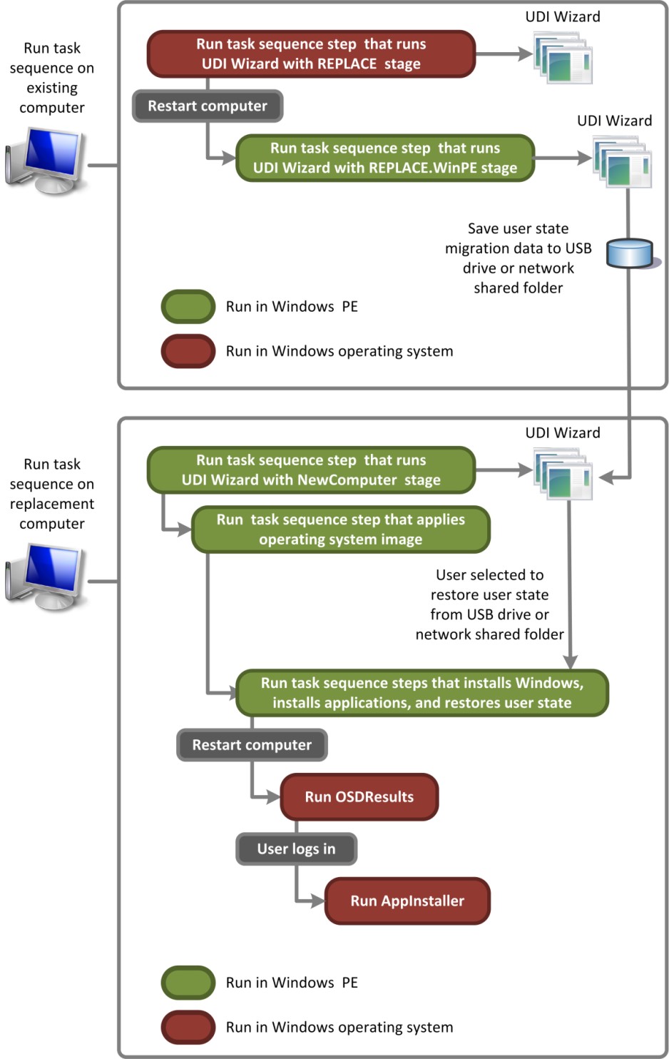
Figure 5. Process flow for UDI performing the Replace Computer deployment scenario
Overview of Built-in UDI Components
UDI comes with built-in Configuration Manager task sequences, stage groups, stages, tasks, validators, and wizard pages that can perform most common deployment scenarios without the assistance of a developer. These built-in components can be configured using the UDI Wizard Designer:
For more information about the built-in UDI components, see the following sections in the Microsoft Deployment Toolkit Reference:
"UDI Stage Reference"
"UDI Wizard Page Reference"
"UDI Task Reference"
"UDI Validator Reference"
In addition to these built-in components, you can create custom wizard pages, wizard page editors, tasks, and validators using the UDI software development kit (SDK). The UDI SDK is installed with MDT and contains example solutions for Microsoft Visual Studio 2010. For more information about extending UDI using the UDI SDK, see the MDT document User-Driven Installation Developers Guide.
Preparing the UDI Deployment Environment
After you have prepared the prerequisite infrastructure for MDT, you are ready to prepare the MDT deployment environment for UDI.
To prepare the MDT deployment environment for UDI deployments
Preparing the prerequisite infrastructure as described in Prepare the Prerequisite Infrastructure for UDI Deployments.
Install a new instance of MDT on the deployment server, or upgrade an existing instance of MDT to MDT as described in Install or Upgrade to MDT for UDI Deployments.
Obtain the software that UDI requires as described in Obtain the Software That the UDI Deployment Process Requires.
Enable Configuration Manager console integration with MDT as described in Enable Configuration Manager Console Integration for UDI.
Prepare the Prerequisite Infrastructure for UDI Deployments
UDI deployments require that a properly configured Configuration Manager infrastructure exist prior to installing MDT and performing deployments. Ensure that your new or existing Configuration Manager infrastructure is specifically optimized for the Operating System Deployment feature.
Note
Windows PowerShell version 2.0 or later must be installed on any computer on which MDT is installed for management of UDI deployments.
For more information about:
Hardware and software requirements for Configuration Manager, see Supported Configurations for Configuration Manager.
Configuring a Configuration Manager infrastructure to support UDI deployments, see the section, "Step 1: Prepare the Prerequisite Infrastructure", in the MDT document Quick Start Guide for User-Driven Installation.
Install or Upgrade to MDT for UDI Deployments
The first step in performing UDI deployments is to have at least one instance of MDT running in your environment. Install MDT on each computer that has the Configuration Manager console installed and that you will use to create or edit task sequences that MDT generates. If your existing environment has:
No computers currently running MDT or a previous version of MDT, install one or more new instances of MDT as described in Installing a New Instance of MDT.
One or more computers running a previous version of MDT, upgrade those instances to MDT as described in Upgrading to MDT. After the upgrade process is complete:
Run the Configure ConfigMgr Integration Wizard. This wizard must be run after the upgrade to register the new components and install the UDI new task sequence templates.
Ensure you create a new Microsoft Deployment Toolkit Files package for any new UDI task sequences you create. The existing Microsoft Deployment Toolkit Files package can be used for any UDI task sequences created prior to the upgrade, but a new Microsoft Deployment Toolkit Files package must be created for new UDI task sequences.
Ensure any UDI task sequences created prior to the upgrade use the Microsoft Deployment Toolkit Files package that existed prior to the upgrade. You can modify these UDI task sequences, but you cannot use any of the new MDT task sequence actions or steps. To use the new MDT task sequence actions or steps, create a new UDI task sequence.
Obtain the Software That the UDI Deployment Process Requires
Collect the software needed during the UDI deployment process. This software will be imported or added to deployment shares unless it already exists in the deployment share.
Note
UDI requires Configuration Manager.
Required software includes:
Operating system source files for each operating system to be deployed to the reference and target computers
Operating system packages for the operating systems, such as security updates, feature packs, and language packs
Device drivers for the reference and target computers that are not included as part of the operating system
Applications that are to be installed as a part of the operating system image or during the deployment of the reference image
USMT source files used to create a software package that is deployed to the target computers to capture user state migration data
Enable Configuration Manager Console Integration for UDI
Before you can use the Configuration Manager integration features of MDT, run the Configure ConfigMgr Integration Wizard. This wizard copies the appropriate Configuration Manager integration files to the Configuration Manager _root (where Configuration Manager _root is the folder in which the Configuration Manager console is installed).
The wizard also adds WMI classes for the new MDT custom actions. You add these classes by compiling a .mof file that contains the new class definitions.
To run the Configure ConfigMgr Integration Wizard
Note
The Configuration Manager console should be closed when performing this procedure.
Select Start, and then point to All Programs. Point to Microsoft Deployment Toolkit, and then select Configure ConfigMgr Integration.
The Configure ConfigMgr Integration Wizard starts.
Complete the Configure ConfigMgr Integration Wizard using the information in Table 137. Accept the default values unless otherwise specified.
Table 137. Information for Completing the Configure ConfigMgr Integration Wizard
On this wizard page Do this Options 1. Verify that the Install the MDT console extensions for System Center 2012 R2 Configuration Manager check box is selected.
2. Verify that the Add the MDT task sequence actions to a System Center 2012 R2 Configuration Manager server check box is selected.
3. In Site server name, type ConfigMgr_server_name (where ConfigMgr_server_name is the name of the Configuration Manager server on which to install MDT integration).
4. In Site code, type ConfigMgr_site_code (where ConfigMgr_site_code is the Configuration Manager site code that installs MDT integration).
5. Select Next.
The Site Server Name and Site Code fields will be automatically populated with the most recent connection details if the Configuration Manager console has been opened once.Confirmation Select Finish. The Configure ConfigMgr Integration Wizard finishes, and MDT is integrated with Configuration Manager.
Preparing for UDI Deployment to the Reference Computer
Regardless of the MDT deployment scenario you are performing using UDI, always start by creating a reference computer, and then capturing an image of that computer. Later in the MDT deployment process, you will deploy the captured image of your reference computer to the appropriate target computers. In addition, you can use existing operating system images in WIM format.
Create a reference computer for each image that you want to create for deployment to the target computers. For more information about determining the number of images required in your organization (and subsequently the number of reference computers required), see Estimate Storage Requirements for Configuration Manager Distribution Points. For more information about the use of reference computers in MDT deployments, see Using Reference Computers in MDT Deployments.
To prepare for deployment to the reference computer
Create a new task sequence that will deploy the target operating system to the reference computer using the Create MDT Task Sequence Wizard in the Configuration Manager console as described in Creating a UDI Task Sequence Using MDT Task Sequence Templates.
Tip
Create the task sequence for deploying to the reference computer based on the User-Driven Installation task sequence template included in MDT.
Configure Configuration Manager to contain the appropriate software for deployment to the reference computer, including the following:
Configuring applications and operating system packages as described in Managing Software Packages in Configuration Manager which is the same process for UDI and ZTI deployments.
Configuring device drivers as described in Managing Device Drivers in Configuration Manager, which is the same process for UDI and ZTI deployments.
Ensure that all packages, including operating system deployment packages, that the new UDI task sequence uses are properly distributed to the assigned distribution points as described in Managing Distribution Points in Configuration Manager, which is the same process for UDI and ZTI deployments.
Note
Most production networks have multiple distribution points. When performing this step in a production environment, select the appropriate distribution points for the network.
Customize the MDT configuration files to the needs of your organization as described in Configuring MDT Deployments.
Important
If you are capturing an image of the reference computer, you must at least add the DoCapture property to the CustomSettings.ini file for the task sequence by specifying
DoCapture=YESorDoCapture=SYSPREP.Optionally, enable monitoring of the MDT deployment process as described in Monitoring MDT Deployments.
Customize the task sequence to the needs of your organization as described in Configuring ZTI Task Sequence Steps in Configuration Manager, which is the same process for UDI and ZTI deployments.
Note
The UDI deployment process is unable to perform Sysprep operations on a target computer that is encrypted by using BitLocker Drive Encryption. Do not enable BitLocker on the reference computer, and enable BitLocker on the target computers only after the target operating system is completely deployed.
Deploying To and Capturing an Image of the Reference Computer Using UDI
After the distribution points are updated, advertise the task sequence to the reference computer and start the reference computer with the bootable Windows PE image created earlier in the process. The task sequence created earlier will deploy the target operating system, device drivers, operating system packages, and applications to the reference computer, and then capture an image of the reference computer.
To deploy to and capture an image of the reference computer
Add the reference computer to the Configuration Manager site database as described in Manually Adding Computers to the Site Database in Configuration Manager , which is the same process for UDI and ZTI deployments.
Create a collection that contains the reference computer as described in Managing Computer Collections in Configuration Manager, which is the same process for UDI and ZTI deployments.
Deploy the task sequence to the reference computer as described in Managing Task Sequence Deployment in Configuration Manager, which is the same process for UDI and ZTI deployments.
Optionally, enable monitoring of the MDT deployment process as described in Monitoring MDT Deployments.
Create a task sequence bootable media disk by using the Task Sequence Media Wizard as described in Creating Task Sequence Bootable Media in Configuration Manager, which is the same process for UDI and ZTI deployments.
Start the reference computer with the task sequence bootable media disk as described in Deploying an Operating System Using Task Sequence Bootable Media in Configuration Manager which is the same process for UDI and ZTI deployments.
Preparing for UDI Deployment to Target Computers
After the images of the reference computers are captured, deploy them to the target computers. In preparation for deploying the captured images to the target computers, create one or more task sequences for deploying the captured images, ensure that the necessary deployment resources exist, and customize the MDT deployment process.
To prepare for UDI deployment to target computers
Prepare network shares for storing migration data and MDT deployment logs as described in Preparing the MDT Migration Resources.
Optionally, prepare Windows Deployment Services to start the appropriate Windows PE images that will in turn start the UDI deployment process to the target computers as described in Preparing Windows Deployment Services for UDI Deployments.
Create additional distribution points to help in larger deployments as described in Managing Distribution Points in Configuration Manager, which is the same process for UDI and ZTI deployments.
Prepare the UDI task sequences, the MDT configuration files, the UDI Wizard configuration files, and the MDT DB for each deployment scenario as described in the following sections:
Prepare for the New Computer Deployment Scenario to Target Computers Using UDI
Prepare for the Refresh Computer Deployment Scenario to Target Computers Using UDI
Prepare for the Replace Computer Deployment Scenario to Target Computers Using UDI
Depending on the target computers in your organization, any combination of these deployments scenarios might be necessary. For more information about MDT deployment scenarios, see Identifying Deployment Scenarios.
Prepare for the New Computer Deployment Scenario to Target Computers Using UDI
In the New Computer deployment scenario, you deploy a new installation of a Windows operating system to a new computer. There is no user migration information to save and restore and no existing file systems to preserve. Use the User-Driven Installation task sequence template to deploy the captured image of the reference computer to the target computer.
To prepare for the New Computer deployment scenario to target computers using UDI
Create a new task sequence that will deploy the target operating system to the reference computer using Create MDT Task Sequence Wizard in the Configuration Manager Console as described in Creating a ZTI Task Sequence Using MDT Task Sequence Templates in Configuration Manager, but ensure that you specifically follow the configuration settings on the wizard pages listed in Table 138 and select the appropriate values on the other wizard pages based on your organization's requirements.
Tip
Create the task sequence for deploying to the reference computer based on the Client Task Sequence task sequence template included in MDT.
Table 138. Information for Completing the Create MDT Task Sequence Wizard for Performing New Computer Deployment Scenario Using UDI
On this wizard page Do this OS Image Select Create a new OS image, and specify the fully qualified UNC path to the WIM image captured from the reference computer. Deployment Method Select Perform a "User-Drive Installation". Configure the application and operating system packages for deployment to the reference computer, including:
Configuring applications and operating system packages as described in Managing Software Packages in Configuration Manager, which is the same process for UDI and ZTI deployments.
Configuring device drivers as described in Managing Device Drivers in Configuration Manager, which is the same process for UDI and ZTI deployments.
Ensure that all packages, including operating system deployment packages, that the new UDI task sequence uses are properly distributed to the assigned distribution points as described in Managing Distribution Points in Configuration Manager, which is the same process for UDI and ZTI deployments.
Note
Most production networks have multiple distribution points. When performing this step in a production environment, select the appropriate distribution points for the network.
Customize the MDT configuration files to the needs of your organization as described in Configuring MDT Deployments.
Optionally, customize the MDT DB to the needs of your organization as described in Performing Deployments Using the MDT DB (if you are using the MDT DB to provide MDT configuration information).
Customize the task sequence to the needs of your organization as described in Configuring ZTI Task Sequence Steps in Configuration Manager, which is the same process for UDI and ZTI deployments.
Customize the UDI Wizard configuration files to the needs of your organization as described in Configuring UDI Wizard Behavior.
Optionally, enable monitoring of the MDT deployment process as described in Monitoring MDT Deployments.
Ensure that all packages, including operating system deployment packages, that the new UDI task sequence uses are properly distributed to the assigned distribution points as described in Managing Distribution Points in Configuration Manager, which is the same process for UDI and ZTI deployments.
Note
Most production networks have multiple distribution points. When performing this step in a production environment, select the appropriate distribution points for the network.
Update the distribution points so that any changes to the packages are distributed properly as described in Managing Distribution Points in Configuration Manager, which is the same process for UDI and ZTI deployments.
Note
Most production networks have multiple distribution points. When performing this step in a production environment, select the appropriate distribution points for the network.
Prepare for the Refresh Computer Deployment Scenario to Target Computers Using UDI
In the Refresh Computer deployment scenario, a computer is refreshed, including computers that must be re-imaged for image standardization or to address a problem. There is user migration information to save and restore but no existing file systems to preserve. Use the User Driven Installation Task Sequence template to deploy the captured image of the reference computer to the target computer.
To prepare for the Refresh Computer deployment scenario to target computers using UDI
Create a new task sequence that will deploy the target operating system to the reference computer using the Create MDT Task Sequence Wizard in the Configuration Manager console as described in Creating a UDI Task Sequence Using MDT Task Sequence Templates, but ensure that you follow the configuration settings on the wizard pages listed in Table 139 and select the appropriate values on the other wizard pages for your organization's requirements.
Tip
Create the task sequence for deploying to the reference computer based on the Client Task Sequence task sequence template included in MDT.
Table 139. Information for Completing the Create MDT Task Sequence Wizard for Performing Refresh Computer Deployment Scenario Using UDI
On this wizard page Do this OS Image Select Create a new OS image, and specify the fully qualified path to the WIM image captured from the reference computer. Deployment Method Select Perform a "User-Drive Installation". Configure the appropriate software for deployment to the target computer in the Configuration Manager console, including:
Configuring applications and operating system packages as described in Managing Software Packages in Configuration Manager
Configuring device drivers as described in Managing Device Drivers in Configuration Manager
Optionally, customize the MDT configuration files or the MDT DB to the needs of your organization as described in:
Customize the task sequence to the needs of your organization as described in Configuring ZTI Task Sequence Steps in Configuration Manager, which is the same process for UDI and ZTI deployments.
Configure the behavior of the UDI Wizard to the needs of your organization as described in Configuring UDI Wizard Behavior.
Optionally, enable monitoring of the MDT deployment process as described in Monitoring MDT Deployments.
Ensure that all packages, including operating system deployment packages, that the new UDI task sequence uses are properly distributed to the assigned distribution points as described in Managing Distribution Points in Configuration Manager, which is the same process for UDI and ZTI deployments.
Note
Most production networks have multiple distribution points. When performing this step in a production environment, select the appropriate distribution points for the network.
Update the distribution points so that any changes to the packages are distributed properly as described in Managing Distribution Points in Configuration Manager, which is the same process for UDI and ZTI deployments.
Note
Most production networks have multiple distribution points. When performing this step in a production environment, select the appropriate distribution points for the network.
Prepare for the Replace Computer Deployment Scenario to Target Computers Using UDI
In the Replace Computer deployment scenario, one computer replaces another computer. Create a computer association record that associates the existing target computer and the new target computer. The existing user state migration data is saved from the existing target computer. Then, a new installation of Windows is deployed to a new computer. Finally, the user state data is restored to the new computer. There are no existing file systems to preserve.
Important
You must establish a computer association record for each existing target computer and each new target computer prior to performing the deployment to the target computer.
Use the:
User Driven Installation Replace Task Sequence template to save the user state migration of the existing target computer
Important
Run this task sequence before running the task sequence based on the User Driven Installation Task Sequence template on the new target computer.
Client Task Sequence template to deploy the captured image of the reference computer to the new target computer and restore the user state migration data
Important
Run this task sequence after running the task sequence based on the User Driven Installation Replace Task Sequence template on the existing target computer.
To prepare for the Replace Computer deployment scenario to target computers using UDI
Create a computer association between the existing target computer and the new target computer as described in "How to Perform a Side-by-Side Operating System Deployment," in the section, "How to Deploy Operating Systems in Configuration Manager," in Configuration Manager Documentation Library, which is installed with Configuration Manager.
Create a new task sequence that will save the user state migration data of the existing target computer as described in Creating a UDI Task Sequence Using MDT Task Sequence Templates.
Tip
Create the task sequence for capturing the user state migration data from the target computer based on the User Driven Installation Task Replace Sequence template included in MDT.
Create a new task sequence that will deploy the captured image of the reference computer to the target computer, and restore the user state migration data saved by the User Driven Installation Replace Task Sequence as described in Creating a UDI Task Sequence Using MDT Task Sequence Templates, but ensure that you specifically follow the configuration settings on the wizard pages listed in Table 140 and select the appropriate values on the other wizard pages for your organization's requirements.
Tip
Create the task sequence for deploying to the target computer based on the ClientTask Sequence template included in MDT.
Table 140. Information for Completing the Create MDT Task Sequence Wizard for Performing the Replace Computer Deployment Scenario using UDI
On this wizard page Do this OS Image Select Create a new OS image, and specify the fully qualified UNC path to the WIM image captured from the reference computer. Deployment Method Select Perform a "User-Drive Installation". Configure the appropriate software for deployment to the target computer in the Configuration Manager console, including:
Configuring applications and operating system packages as described in Managing Software Packages in Configuration Manager, which is the same process for UDI and ZTI deployments.
Configuring device drivers as described in Managing Device Drivers in Configuration Manager, which is the same process for UDI and ZTI deployments.
Customize the MDT configuration files or the MDT DB to the needs of your organization as described in:
Customize the task sequences to the needs of your organization as described in Configuring ZTI Task Sequence Steps in Configuration Manager, which is the same process for UDI and ZTI deployments.
Optionally, enable monitoring of the MDT deployment process as described in Monitoring MDT Deployments.
Ensure that the distribution points for the packages and operating system images that the new ZTI task sequence uses are distributed properly as described in Managing Distribution Points in Configuration Manager, which is the same process for UDI and ZTI deployments.
Note
Most production networks have multiple distribution points. When performing this step in a production environment, select the appropriate distribution points for the network.
Update the distribution points so that any changes to the packages are distributed properly as described in Managing Distribution Points in Configuration Manager, which is the same process for UDI and ZTI deployments.
Note
Most production networks have multiple distribution points. When performing this step in a production environment, select the appropriate distribution points for the network.
Deploying Captured Images to Target Computers Using UDI
The deployment of the captured images to the target computers is slightly different for each MDT deployment scenario using UDI. Deploy the captured image of the reference computer to target computers for each respective deployment scenario in your organization.
To deploy the capture image of the reference computer to the target computers using UDI
Add the target computer to the Configuration Manager site database:
Manually, as described in Manually Adding Computers to the Site Database in Configuration Manager, which is the same process for UDI and ZTI deployments.
Automatically in Configuration Manager as described in the section, "How to Manage Unknown Computer Deployments in Configuration Manager," in the Configuration Manager Documentation Library, which is installed with Configuration Manager.
Note
If the target computers already exist in the Configuration Manager Site database, then this step is not necessary.
Create a collection that contains the target computers as described in Managing Computer Collections in Configuration Manager, which is the same process for UDI and ZTI deployments.
Note
Create a collection for each MDT deployment scenario to be performed, and ensure that the collection includes the target computers requiring the corresponding deployment scenario.
Create an advertisement for the target computer task sequences as described in Managing Task Sequence Deployment in Configuration Manager, which is the same process for UDI and ZTI deployments.
Provide a method for starting the target computers by doing any combination of the following:
Create a task sequence bootable media disk using the Task Sequence Media Wizard as described in Creating Task Sequence Bootable Media in Configuration Manager, which is the same process for UDI and ZTI deployments.
Prepare Windows Deployment Services to start the appropriate Windows PE images that will in turn start the UDI deployment process to the target computers as described in Preparing Windows Deployment Services for ZTI Deployments Using Configuration Manager, which is the same process for UDI and ZTI deployments.
Deploy the captured reference computer image to the target computers for each deployment scenario as described in:
Deploy Captured Images to Target Computers in the New Computer Deployment Scenario Using UDI
Deploy Captured Images to Target Computers in the Refresh Computer Deployment Scenario Using UDI
Deploy Captured Images to Target Computers in the Replace Computer Deployment Scenario Using UDI
Depending on the target computers in your organization, any combination of deployments scenarios might be necessary. For more information about the MDT deployment scenarios, see Identifying Deployment Scenarios.
Deploy Captured Images to Target Computers in the New Computer Deployment Scenario Using UDI
Start the target computer with the task sequence bootable media created earlier in the process or from Windows Deployment Services. Either method starts Windows PE on the target computer and initiates the UDI deployment process. At the end of the process, the captured image of the reference computer is deployed on the target computer.
To deploy the capture images to the target computers in the New Computer Deployment Scenario using UDI
Start the target computer with the task sequence bootable media created earlier in the process or from Windows Deployment Services.
The Task Sequence Wizard starts.
Complete the Task Sequence Wizard, ensuring that you specifically follow the configuration settings on the wizard pages listed in Table 141 and select the appropriate values on the other wizard pages for your organization's requirements.
Note
This wizard will not appear if you configure UDI to perform a PXE boot and have configured a mandatory advertisement or if only one task sequence is advertised to the target computer.
Table 141. Information for Completing the Task Sequence Wizard in the New Computer Deployment Scenario using UDI
On this wizard page Do this Select a Task Sequence Select the task sequence you created for the target computer deployment for the New Computer deployment scenario. The wizard starts, and the operating system deployment starts. Eventually the task sequence starts the UDI Wizard.
Optionally, view the MDT deployment process using the Monitoring node in the Deployment Workbench or using the Get-MDTMonitorData cmdlet.
For more information about monitoring MDT deployments, see View MDT Deployment Progress.
Complete the UDI Wizard by selecting the appropriate values on the wizard pages for your organization's requirements as described in Running the UDI Wizard.
Deploy Captured Images to Target Computers in the Refresh Computer Deployment Scenario Using UDI
Start this scenario by running the Configuration Manager task sequence deployment (advertisement) for capturing the user state migration data that you created earlier in the process. This task sequence runs in the current operating system on the existing target computer.
To deploy the capture images to the target computers in the Refresh Computer Deployment Scenario Using UDI
On the target computer, run the Configuration Manager deployment (advertisement) for capturing the Refresh Computer deployment scenario that you created earlier in the deployment process.
The task sequence starts. Eventually, the task sequence starts the UDI Wizard.
Complete the UDI Wizard by selecting the appropriate values on the wizard pages for your organization's requirements, as described in Running the UDI Wizard.
Optionally, view the MDT deployment process using the Monitoring node in the Deployment Workbench or using the Get-MDTMonitorData cmdlet.
For more information about monitoring MDT deployments, see View MDT Deployment Progress.
The task sequence runs in Windows PE to capture user state migration data. The task sequence restarts the computer, starts Windows PE, and then initiates installation of the new operating system. The task sequence restarts the computer, starts the new operating system, restores the user state migration data, installs any packages, installs any applications, and performs any other actions configured in the task sequence. Finally, the OSD Results program, OSDResults.exe, runs and displays the results of the deployment. The target computer is now deployed.
Deploy Captured Images to Target Computers in the Replace Computer Deployment Scenario Using UDI
The Replace Computer deployment scenario requires two separate steps to complete the migration. First, run the deployment (advertisement) for the task sequence you created to capture the user state migration data from the existing target computer (old computer). Second, run the UDI Wizard to deploy the captured image of the reference computer to the new target computer (new computer) and restore the user state saved earlier in the process.
To deploy captured images of the reference computer to target computers in the Replace Computer deployment scenario using UDI
Save the user state migration data from the existing target computer as described in Save the User State Migration Data in the Replace Computer Deployment Scenario Using UDI.
Deploy the captured image of the reference computer to the new target computer as described in Deploy the Captured Image and User State Migration Data in the Replace Computer Deployment Scenario Using UDI.
Save the User State Migration Data in the Replace Computer Deployment Scenario Using UDI
Start this scenario by running the task sequence deployment (advertisement) for capturing the user state migration data that you created earlier in the process. This task sequence runs in the current operating system on the existing target computer.
To save the user state migration data from the existing target computers in the Replace Computer Deployment Scenario using UDI
Run the task sequence deployment (advertisement) for capturing user state migration data that you created earlier in the process Refresh Computer deployment scenario.
Optionally, view the MDT deployment process using the Monitoring node in the Deployment Workbench or using the Get-MDTMonitorData cmdlet.
For more information about monitoring MDT deployments, see View MDT Deployment Progress.
The task sequence runs in the current operating system to capture user state migration data. At the end of the task sequence, the user state migration data of the existing target computer is saved to the Configuration Manager state migration point.
Deploy the Captured Image and User State Migration Data in the Replace Computer Deployment Scenario Using UDI
Start the target computer with the ZTI bootable media created earlier in the process or from Windows Deployment Services. The ZTI bootable media starts Windows PE on the target computer and initiates the UDI deployment process. At the end of the deployment process, the captured image of the reference computer is deployed on the target computer, and the user state migration data is restored from the Configuration Manager state migration point.
To complete the Windows Deployment Wizard in the Replace Computer deployment scenario for deploying the captured image using UDI
Start the reference computer with the ZTI bootable media created earlier in the process or from Windows Deployment Services.
Windows PE starts, and then the Windows Deployment Wizard starts.
Complete the Task Sequence Wizard, ensuring that you follow the configuration settings for the wizard pages listed in Table 142 and select values on the other wizard pages for your organization's requirements.
Note
This wizard will not appear if you configure ZTI to perform a PXE boot and have configured a mandatory advertisement or if only one task sequence is advertised to the target computer.
Table 142. Information for Completing the Task Sequence Wizard for the Replace Computer Deployment Scenario Using UDI
On this wizard page Do this Select a Task Sequence Select the task sequence you created for the target computer deployment in the Replace Computer deployment scenario to deploy the captured image of the reference computer to the new target computer. The task sequence starts. Eventually, the task sequence starts the UDI Wizard.
Complete the UDI Wizard by selecting the appropriate values on the wizard pages for your organization's requirements, as described in Running the UDI Wizard.
Optionally, view the MDT deployment process using the Monitoring node in the Deployment Workbench or using the Get-MDTMonitorData cmdlet.
For more information about monitoring MDT deployments, see View MDT Deployment Progress.
The task sequence starts Windows PE and then initiates installation of the new operating system. The task sequence restarts the computer, starts the new operating system, restores the user state migration data, installs any packages, installs any applications, and performs any other actions configured in the task sequence. Finally, the OSD Results program, OSDResults.exe, runs and displays the results of the deployment. The target computer is now deployed.
Managing UDI Deployments
You manage UDI deployments through the Configuration Manager console and the UDI Wizard Designer. You use the Deployment Workbench in UDI deployments only to configure the MDT DB. The wizard used to create UDI task sequences are integrated into the Configuration Manager console. You can use the UDI Wizard Designer to configure the behavior of the UDI Wizard.
Manage UDI deployments by:
Reviewing UDI administration process as described in Overview of UDI Administration
Creating a new task sequence for UDI deployments using the Create MDT Task Sequence Wizard as described in Creating a UDI Task Sequence Using MDT Task Sequence Templates
Managing operating systems for UDI deployments in the Configuration Manager Console as described in Managing Operating Systems in Configuration Manager which is the same process for UDI and ZTI deployments
Managing device drivers for UDI deployments in the Configuration Manager Console as describe in Managing Device Drivers in Configuration Manager, which is the same process for UDI and ZTI deployments
Deploying an operating system using task sequence bootable media as described in Deploying an Operating System Using Task Sequence Bootable Media in Configuration Manager, which is the same process for UDI and ZTI deployments
Creating task sequence bootable media for UDI as described in Creating Task Sequence Bootable Media in Configuration Manager, which is the same process for UDI and ZTI deployments
Creating boot images for use with UDI using the Create Image Using Microsoft Deployment Wizard as described in Creating ZTI Boot Images in Configuration Manager, which is the same process for UDI and ZTI deployments
Managing software packages for UDI in the Configuration Manager console as described in Managing Software Packages in Configuration Manager, which is the same process for UDI and ZTI deployments
Managing advertisements for UDI as described in Managing Task Sequence Deployment in Configuration Manager, which is the same process for UDI and ZTI deployments
Manually adding computers to the site database for UDI as described in Manually Adding Computers to the Site Database in Configuration Manager, which is the same process for UDI and ZTI deployments
Managing computer collections for UDI as described in Managing Computer Collections in Configuration Manager, which is the same process for UDI and ZTI deployments
Managing distribution points for UDI as described in Managing Distribution Points in Configuration Manager, which is the same process for UDI and ZTI deployments
Configuring individual UDI task sequence steps as described in Configuring ZTI Task Sequence Steps in Configuration Manager, which is the same process for UDI and ZTI deployments
Configuring the UDI Wizard behavior by customizing the UDI Wizard configuration file as described in Configuring UDI Wizard Behavior
Creating a custom wizard page to collect additional deployment information as described in Creating Custom Wizard Pages Using the Build Your Own Page Feature
Overview of UDI Administration
The goal of UDI administration is to configure the user experience in the UDI Wizard and ultimately control the deployment of Windows operating systems and applications to target computers. You configure the UDI user experience by using the UDI Wizard Designer and by customizing the Configuration Manager task sequences used with UDI in the Configuration Manager Console.
The primary tool for administering UDI is the UDI Wizard designer. The UDI Wizard Designer is installed as a part of MDT, which is installed on the same computer at the Configuration Manager Console. Because UDI is built-on the OSD feature in Configuration Manager, you will also use the Configuration Manager Console to administer specific aspects of UDI deployments.
Figure 6 illustrates the high-level overview of the UDI administrative process.
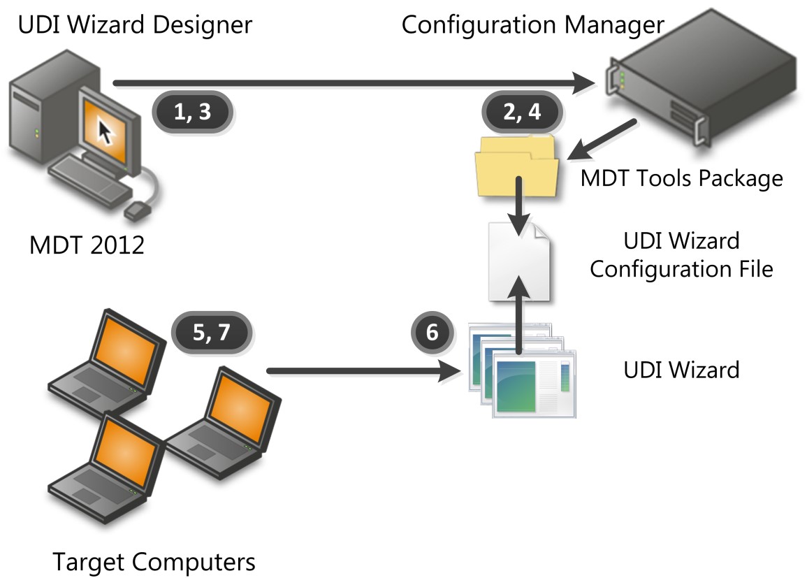
Figure 6. Overview of UDI administration process
The UDI administration process, as illustrated in Figure 6, is performed as follows:
Create a UDI task sequence based on the task sequence templates built-in to MDT.
As a part of creating the task sequence, the Create MDT Task Sequence wizard creates an MDT toolkit package that contains the contents of the installation_folder\Templates\Distribution folder (where installation_folder is the folder where you installed MDT). The toolkit package is referenced by the Use Toolkit Package task sequence step.
For more information about the built-in UDI tasks sequence templates in MDT, see Identify the UDI Task Sequence Templates in MDT.
Distribute the MDT toolkit package to Configuration Manager distribution points.
The UDI Wizard and UDI Wizard configuration file are contained in the package. The UDI Wizard (UDIWizard.exe) is in the Tools folder in the package. The UDI Wizard configuration file (UDIWizard_Config.xml) is in the Scripts folder in the package.
Customize the UDI Wizard configuration file and application information file using the UDI Wizard Designer.
The UDI Wizard configuration file (UDIWizard_Config.xml) and application information file (UDIWizard_Config.xml.app) are stored in the Scripts folder in the MDT toolkit package.
Update the distribution points with the modified version of the UDI Wizard configuration file and corresponding application information file in the MDT toolkit package.
The target computers initiate the UDI task sequence which runs the UDI Wizard at the appropriate point in the task sequence.
The UDI Wizard is initiated using the UDI Wizard task sequence step.
The UDI Wizard runs and the deployment configuration information is collected from the user.
The UDI Wizard reads the UDI Wizard configuration file to determine the wizard pages to display and the sequence of the pages. The user completes the UDI Wizard by providing the necessary deployment information. The UDI Wizard updates task sequence variables based on the information provided. The updated task sequence variables are used by the UDI task sequence to perform the balance of the deployment.
The remainder of the task sequence steps in the UDI task sequence complete and the OSD Results dialog is displayed at the end of the deployment. Any applications installed during the task sequences are identified the first time a user logs in using AppInstaller.
AppInstaller enables Configuration Manager to identify any applications installed using the Application model during the task sequence. This allows Configuration Manager to use features such as the monitoring feature.
Creating a UDI Task Sequence Using MDT Task Sequence Templates
Use the Create MDT Task Sequence Wizard in the Configuration Manager console to create task sequences in Configuration Manager that are integrated with MDT. MDT includes task sequence templates that you can use to deploy the reference and target computers.
Create UDI task sequences using the MDT task sequence templates by:
Identifying the UDI task sequence templates that are a part of MDT as described in Identify the UDI Task Sequence Templates in MDT
Identifying the packages and images that the UDI task sequence templates require as described in Identify the Packages and Images That the UDI Task Sequence Templates Require
Creating UDI task sequences as described in Create UDI Task Sequences Using the Create MDT Task Sequence Wizard
Configure UDI task sequences to deploy different operating systems as described in Configure UDI Task Sequences to Deploy Different Operating Systems
Identify the UDI Task Sequence Templates in MDT
MDT includes task sequence templates that are used to create MDT task sequences in Configuration Manager. The task sequence templates included in MDT are described in Identify the Task Sequence Templates in MDT in Configuration Manager.
Of the templates described in Identify the Task Sequence Templates in MDT in Configuration Manager, the following are used in MDT deployment scenarios using UDI:
Client Task Sequence. This task sequence template is used for the MDT New Computer, Refresh Computer, and Replace Computer deployment scenarios. This task sequence template is also used to build and capture images of the reference computers.
User Driven Installation Replace Task Sequence. This task sequence template is the first step in a two-step process in the MDT Replace Computer deployment scenario and is used to capture user state migration data. The second step in the two step process is the User Driven Installation Task Sequence task sequence template, which is used to:
Deploy the target applications and operating system
Restore the user state migration data saved during the User Driven Installation Replace task Sequence task sequence template in the first step of the process
For more information on the MDT deployment scenarios, see Identifying Deployment Scenarios.
Note
Always use the Create MDT Task Sequence Wizard to create task sequences. Although you can manually create the task sequences, doing so is not recommended.
Identify the Packages and Images That the UDI Task Sequence Templates Require
The UDI task sequence templates require the same packages and images as required by ZTI deployments, as described in Identify the Packages and Images That the MDT Task Sequence Templates in Configuration Manager Require.
Create UDI Task Sequences Using the Create MDT Task Sequence Wizard
The Create MDT Task Sequence Wizard substitutes the packages and images selected for the placeholders in the task sequence templates. After completing the wizard, the new task sequence references the appropriate packages and images.
Note
Always use the Create MDT Task Sequence Wizard to create task sequences based on the MDT task sequence templates. Although you can manually import the task sequence templates, doing so is not recommend.
Create UDI task sequences using the same process for creating ZTI task sequences using the Create MDT Task Sequence Wizard as described in Create ZTI Task Sequences Using the Create MDT Task Sequence Wizard in Configuration Manager
Select the appropriate UDI task sequence template based on the deployment scenario being performed. For more information about the UDI task sequence templates in MDT, see Identify the UDI Task Sequence Templates in MDT.
Configure UDI Task Sequences to Deploy Different Operating Systems
The VolumePage page in built-in UDI stage groups allows you to select from any operating system images that you have configured in the UDI Wizard Designer. However, the task sequence created by the Create MDT Task Sequence wizard references only one specific operating system image in the Apply Operating System Image task sequence step.
When you select the operating system image on the VolumePage page, the UDI Wizard sets the OSDImageName task sequence variable to the value of the image name that was selected. The value of the OSDImageName task sequence variable corresponds to the name of the operating system image in the Operating System Images or Operating System Installers nodes in the Configuration Manager console.
You can configure a UDI task sequence to support the operating systems you have added to the VolumePage page by performing the following steps:
Rename the existing Apply Operating System Image task sequence step to reflect the name of the operating system image being deployed.
Configure a condition for the existing Apply Operating System Image task sequence step that will only run the step when the OSDImageName task sequence variable is equal to the name of the operating system image being deployed.
For each operating system that has been added to the VolumePage page, perform the following steps:
Add a new Apply Operating System Image task sequence step that reflects the name of the operating system image to be deployed.
Configure a condition for the new Apply Operating System Image task sequence step that will only run the step when the OSDImageName task sequence variable is equal to the name of the operating system image to be deployed.
After performing these steps, when the user selected an operating system image on the VolumePage page, the corresponding Apply Operating System Image task sequence step will be run and deploy the appropriate operating system image.
Configuring UDI Wizard Behavior
The User-Driven Installation Task Sequence and User-Driven Installation Replace Task Sequence templates include task sequence steps that run the UDI Wizard. When a task sequence step runs the UDI Wizard, the step also references the UDIWizard_Config.xml file, which controls the behavior of the UDI Wizard and is stored in the Scripts folder of the MDT files package. You can customize the UDIWizard_Config.xml file using the UDI Wizard Designer.
Configure the UDI Wizard behavior by performing the following steps in the UDI Wizard Designer:
Review the UDI Wizard Designer concepts as described in Review UDI Wizard Designer Concepts.
Identify the UDI components used in performing UDI deployments and the relationship between those components as described in Identify UDI Deployment Process Components.
Review the relationship between the UDI wizard pages, UDI wizard page editors, and the UDI Wizard configuration file as described in Review the Relationship Among UDI Wizard Pages, Wizard Page Editors, and the UDI Wizard Configuration File.
Review the UI of the UDI Wizard Designer as described in Review the UDI Wizard Designer User Interface.
Create a new UDI Wizard configuration file as described in Create a New UDI Wizard Configuration File.
Open an existing UDI Wizard configuration file as described in Open an Existing UDI Wizard Configuration File.
Save changes in the UDI Wizard Designer to a UDI Wizard configuration file as described in Save UDI Wizard Configuration Updates.
Override the location and name of the UDI configuration file used by a task sequence as described in Override the Configuration File That the UDI Wizard Uses.
Configure the title and banner image to be displayed in the UDI Wizard as described in Configure the UDI Wizard Title and Banner Image.
Add a wizard page to a stage as described in Add a Wizard Page to a Stage.
Remove a wizard page from a stage as described in Remove a Wizard Page from a Stage.
Change the sequence of a wizard page within a stage as described in Change the Wizard Page Sequence Flow Within a Stage.
Allow or prevent users from entering information in a control on a wizard page as described in Allow or Prevent Users from Entering Information in a Control on a Wizard Page.
Configure the user experience for a wizard page as described in Configure the User Experience for a Wizard Page.
Preview how the wizard pages and wizard page sequence flow the UDI Wizard as described in Preview Wizard Pages and the Wizard Page Sequence Flow.
Add a wizard page to the page library as described in Add a Wizard Page to the Page Library.
Remove a wizard page from the page library as described in Remove a Wizard Page from the Page Library.
Change the sequence of a stage group or a stage within a stage group as described in Change the Sequence of a Stage Group or a Stage.
Prepare for language pack deployment using the UDI Wizard as described in Prepare for Language Pack Deployment in UDI.
Skip (remove) a wizard page from a stage as described in Skip a Wizard Page.
Review UDI Wizard Designer Concepts
The UDI Wizard Designer is a console in MDT that allows you to easily configure the UDI Wizard configuration file. The UDI Wizard Designer can update an existing UDI Wizard configuration file or create a new UDI Wizard configuration file.
Note
If you are unfamiliar with UDI, review the UDI terms and terminology in "UDI Concepts". Familiarizing yourself with these terms and terminology will help you be more successful in applying this guide to your organization.
At a high-level, the UDI Wizard Designer allows you to configure the:
Types of wizard pages that are displayed in the UDI Wizard
Sequence of the wizard pages as they will appear in the UDI Wizard
Configuration settings for each wizard page
For more detailed information about the tasks that can be performed in the UDI Wizard Designer, see Configuring UDI Wizard Behavior.
Identify UDI Deployment Process Components
The UDI deployment process is based on ZTI deployments in MDT and requires Configuration Manager. The UDI process runs as any other MDT task sequence, except that the UDI-specific task sequences run the UDI Wizard at the appropriate steps in the task sequence.
Table 143 lists the UDI deployment process components and a brief description of how they work together in a UDI deployment.
Table 143. UDI Deployment Process Components
| Component | Description |
|---|---|
| UDI Wizard | The UDI Wizard is the UI that allows customization of the deployment process based on configuration settings made in the wizard. The configuration settings are used to modify the task sequence variables and unattended installation files used in the operating system and application deployment process. The UDI Wizard is initiated by the appropriate task sequence steps in task sequences created using UDI task sequence templates. The wizard pages that are displayed in the UDI Wizard and the controls that are active for each wizard page is controlled by the UDI Wizard configuration file. |
| UDI Wizard Designer | The UDI Wizard Designer is used to customize the UDI Wizard configuration file. You can use the UDI Wizard Designer to: - Determine the wizard pages that are displayed in the UDI Wizard - Determine the sequence of the wizard pages that are displayed in the UDI Wizard - Configure default values for controls on the wizard pages - Enable or disable individual controls on the wizard pages |
| UDI Wizard configuration file | The UDI Wizard configuration file is read by the UDI Wizard to determine the wizard pages that are displayed, the sequence of the wizard pages, any default values for controls, and whether controls are enabled or disabled for user interaction. The UDI Wizard configuration file is customized using the UDI Wizard Designer. The default UDI Wizard configuration file is name UDIWizard_Config.xml and is stored in the Scripts folder in the MDT files package. |
| UDI task sequences | The UDI task sequences are created using UDI-related MDT task sequence templates. The UDI task sequence templates include the task sequence step to run the UDI Wizard at the appropriate time in the UDI deployment process. For more information about UDI task sequence templates, see Identify the UDI Task Sequence Templates in MDT. |
Review the Relationship Among UDI Wizard Pages, Wizard Page Editors, and the UDI Wizard Configuration File
For each wizard page displayed in the UDI Wizard, there is a corresponding wizard page editor that can be used to configure that wizard page using the UDI Wizard Designer. The UDI Wizard configuration file (UDIWizard_Config.xml) is used to store the configuration settings for each wizard page. Figure 7 illustrates the relationship between UDI wizard pages, UDI wizard page editors, and the UDI Wizard configuration file.
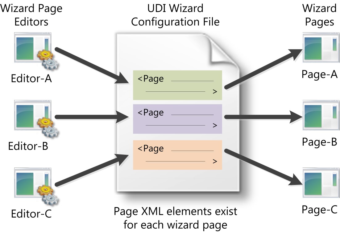
Figure 7. Relationship between UDI wizard pages, UDI wizard page editors, and the UDI Wizard configuration file
In the UDI Wizard configuration file, there is a separate Page XML element for each wizard page that is displayed in the UDI Wizard. When you add a wizard page using the UDI Wizard Designer a corresponding Page XML element is created in the UDI Wizard configuration file. Similarly, when you remove a wizard page, the corresponding Page XML element is removed.
Each Page XML element has child XML elements for each configuration setting for the wizard page. These child XML elements are also configured using the wizard page editors in the UDI Wizard Designer.
For a complete list of the Page XML elements, see the "UDI Wizard Configuration File Schema Reference".
Note
Do not directly modify the UDI Wizard configuration file. Instead, use the appropriate wizard page editors in the UDI Wizard Designer.
Review the UDI Wizard Designer User Interface
The UDI Wizard Designer is used to customize the user experience in the UDI Wizard, including the:
Wizard pages that are displayed in the UDI Wizard (wizard pages can be added or removed)
Sequence of the wizard pages as they are displayed in the UDI Wizard
Controls on each wizard page, such as:
Enabling a control for user interaction
Disabling a control for user interaction
Specifying a default value
Review the UDI Wizard Designer UI by completing the following steps:
Review the UDI Wizard Designer high-level UI elements as described in Review the UDI Wizard Designer High-Level User Interface Elements.
Review the Page Library pane UI elements in the UDI Wizard Designer as described in Review the Page Library Pane in the UDI Wizard Designer.
Review the Flow tab in the details pane the UDI Wizard Designer as described in Review the Flow Tab in the UDI Wizard Designer.
Review the Configure tab in the details pane the UDI Wizard Designer as described in Review the Configure Tab in the UDI Wizard Designer.
Review the UDI Wizard Designer High-Level User Interface Elements
Figure 8 illustrates the UDI Wizard Designer high-level UI elements.
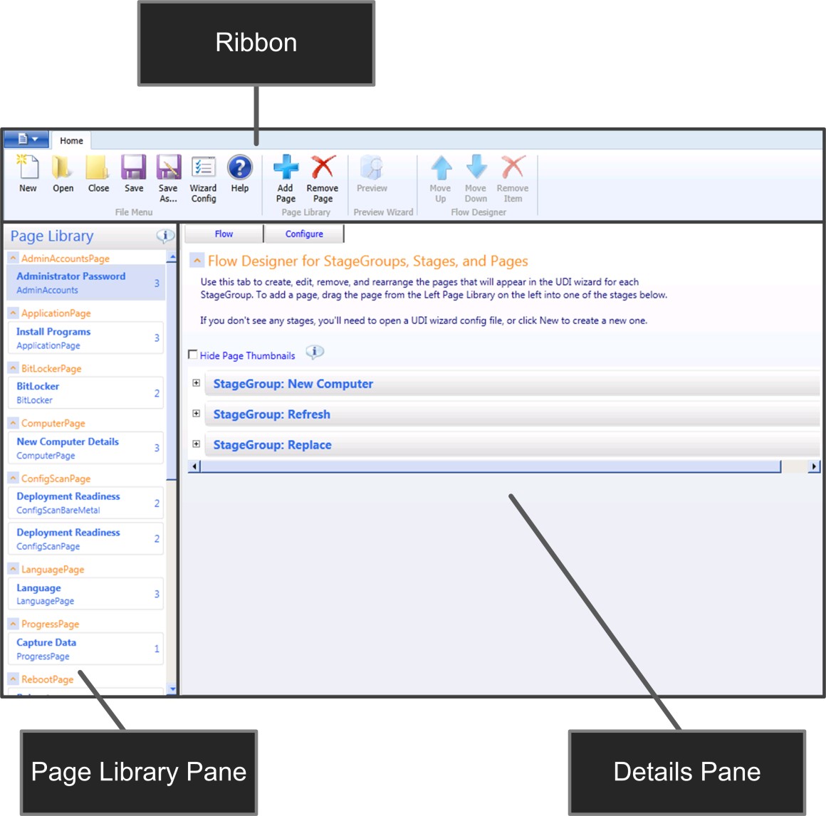
Figure 8. UDI Wizard Designer high-level UI elements
Table 144 lists the high-level UI elements illustrated in Figure 8 and provides a brief description of each element.
Table 144. UDI Wizard Designer High-Level UI Elements
| UI element | Description |
|---|---|
| Ribbon | Provides access to task-based actions that can be performed within the UDI Wizard Designer. The actions are combined into groups, such as the File Menu group or the Flow Designer group. |
| Page Library pane | Contains the wizard pages that are available for use within the UDI Wizard Designer. The number of times that each page is used within the UDI Wizard configuration file is displayed on the far right portion of the wizard page entry. For example, the Language page is used three times while the Scan Configuration page is used twice. |
| Details pane | Provides access to the configuration details of the UDI Wizard configuration file being customized. |
Review the Page Library Pane in the UDI Wizard Designer
Figure 9 illustrates the UI elements in the Page Library pane in the UDI Wizard Designer.

Figure 9. UI elements in the Page Library pane
Table 145 lists the UI elements illustrated in Figure 9 and provides a brief description of each element.
Table 145. UI Elements in the Page Library Pane
| UI element | Description |
|---|---|
| Page instance | Each wizard page in the Page Library is an instance of a specific wizard page type. As shown in REF _Ref307996589 \h Figure 9, there are two instances of the ConfigScanPage wizard page type with the page name of ConfigScanBareMetal and ConfigScanPage. Configuration settings are made to a wizard page instance in the Page Library and affect all stages to which the wizard page is added. |
| Page type | A page type defines a template that can be used to create instances of the wizard page type. The Add New Page dialog box has a list of the wizard page types available in the UDI Wizard Designer. |
| Display name | This is the user-friendly name for the instance of the wizard page type. This value does not have to be unique within the Page Library. |
| Page name | This is the name of the instance of the wizard page type. This value must be unique within a page library. |
| Number of times page is used | This element maintains a count of the number of times that a wizard page instance is used in the stages. For example, as shown in REF _Ref307996589 \h Figure 9, the ComputerPage wizard page instance is used in two different places within the UDI Wizard configuration file. |
Review the Flow Tab in the UDI Wizard Designer
Figure 10 illustrates the UI elements in the Flow tab in the details pane. The Flow tab is used to configure the:
Wizard pages that will be displayed in the UDI Wizard for a specific stage within a specific stage group
Sequence of the wizard pages as they are displayed in the UDI Wizard
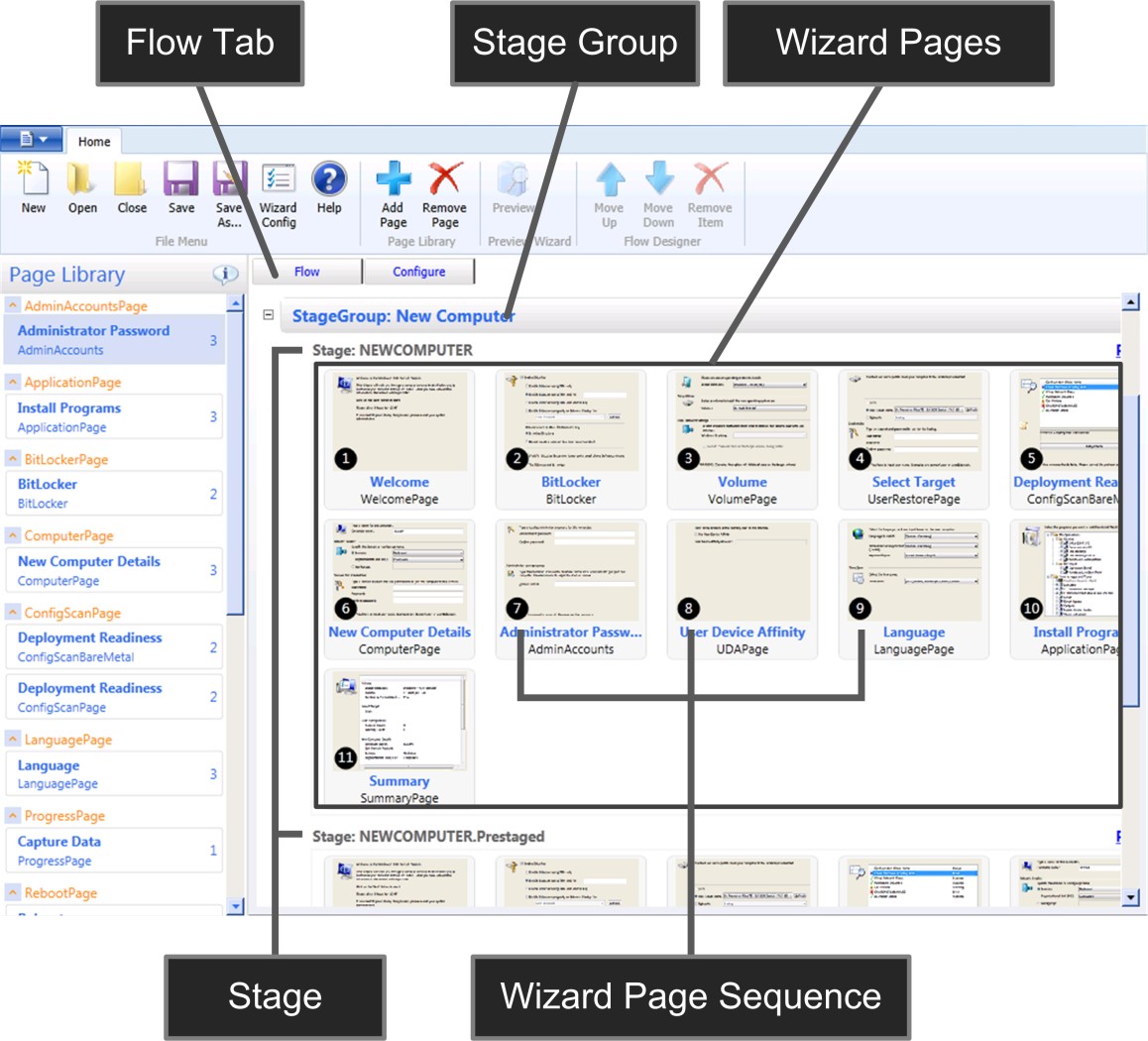
Figure 10. Flow tab in the UDI Wizard Designer
Table 146 lists the UI elements on the Flow tab, which is illustrated in Figure 10, and provides a brief description of each element.
Table 146. UDI Wizard Designer Flow Tab UI Elements
| UI element | Description |
|---|---|
| Stage group | Collection of one or more sets of wizard page groupings (stages) that are used by the deployment scenarios that UDI supports, including the New Computer, Refresh Computer, and Replace Computer MDT deployment scenarios. The stage groups are predefined in UDI. Adding or removing stage groups is not supported. |
| Stage | Collection of one or more wizard pages used at a specific time within a stage group. For the New Computer stage group, MDT includes the following stages: - NEWCOMPUTER. This stage is used for new computer deployments. - NEWCOMPUTER.Prestaged. This stage is used for prestaged media deployments in Configuration Manager. For the Replace Computer stage group, MDT includes the following stages: 1. REPLACE. This stage is used for the portion of the Replace Computer stage group performed in the original operating system running on the target computer. 2. REPLACE.WinPE. This stage is used for the portion of the Replace Computer stage group performed in Windows PE. The stages are predefined in UDI. Adding or removing stages is not supported. |
| Wizard page | The wizard page that is to be displayed in the UDI Wizard for a specific stage within a specific stage group. A wizard page is based on an instance of the wizard page in the Page Library. An instance of a wizard page may appear in multiple stages and stage groups. Configuration settings for a wizard page affect the wizard page instance, not the individual pages that appear in the stages and stage groups. Create a unique instance of a wizard page in the Page Library for each set of unique configuration settings that you want to manage for a specific type of wizard page. |
| Wizard page sequence | The sequence in which the wizard page is displayed in the UDI Wizard for a specific stage within a specific stage group. |
Review the Configure Tab in the UDI Wizard Designer
Figure 11 illustrates the UI elements in the Configure tab in the details pane. You use the Configure tab to configure the individual controls on the wizard page.
Note
Any changes made to the settings on the Configure tab affect the instance of that wizard page in the Page Library. The result is any stage groups or stages that contain the same instance of that wizard page will also reflect the changes in the configuration settings.
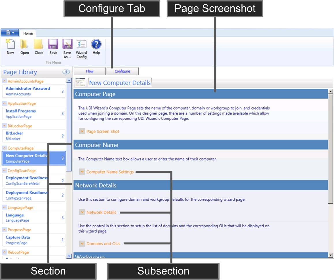
Figure 11. Configure tab in the UDI Wizard Designer
Table 147 lists the UI elements on the Flow tab, which is illustrated in Figure 11, and provides a brief description of each element.
Table 147. UDI Wizard Designer Configure Tab UI Elements
| UI element | Description |
|---|---|
| Page screenshot | Expand to show a sample of the wizard page as displayed in the UDI Wizard. |
| Section | Logical grouping of one or more user controls. |
| Subsection | Logical grouping of one or more user controls within a section. Expand to show the user controls contained within the configuration details. |
If you expand a subsection, you can see the controls within that subsection. Figure 12 illustrates the UI elements for a control beneath a subsection. A subsection may contain multiple controls.
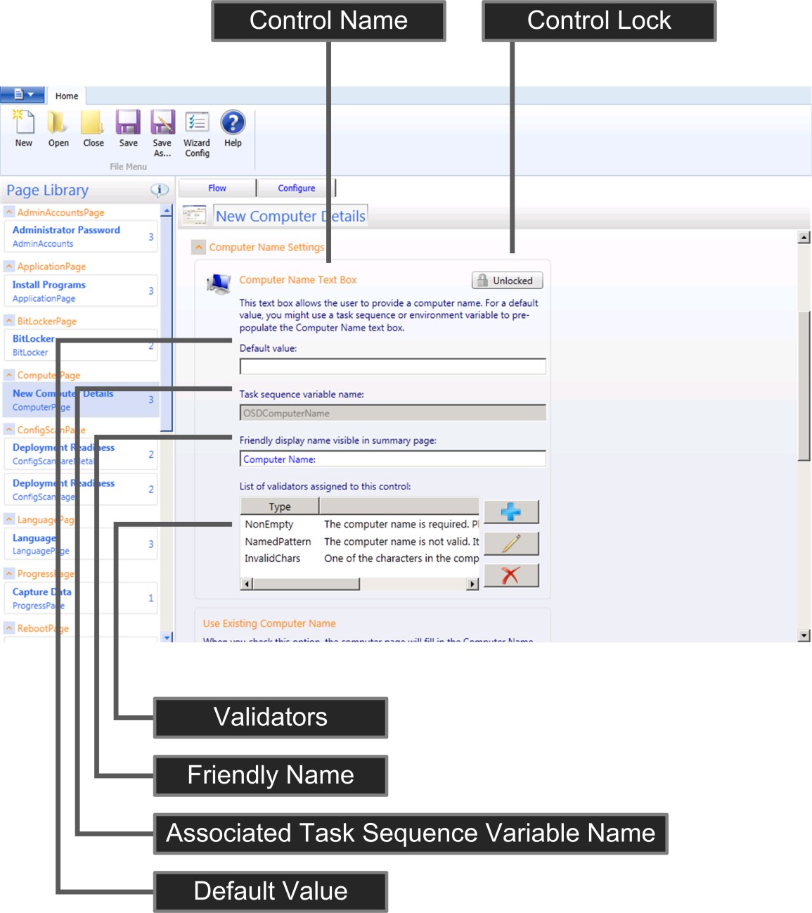
Figure 12. UI elements for a control on the Configure tab in the UDI Wizard Designer
Table 148 lists the UI elements for a control on the Configure tab, which is illustrated in Figure 12, and provides a brief description of each element.
Note
Each control on a wizard page is unique and has different UI elements. The control illustrated in Figure 12 is provided as an example for generalized discussion.
Table 148. UI Elements for a Control on the Configure Tab
| UI element | Description |
|---|---|
| Control lock | Allows you to enable (unlocked) or disable (lock) the control to allow or prevent users from entering information in the control. The status in the button can be one of the following values: - Unlocked. Users are able to interact with the control in the UDI Wizard. - Locked. Users are unable to interact with the control in the UDI Wizard. If you disable a control, you must provide the information collected by the control either as a default value in the control or in the CustomSettings.ini file or in MDT DB. |
| Default value | The value that is displayed in the control by default. If the control is enabled, then the user can override the default value. |
| Associated task sequence variable name | The task sequence variable name associated with the control. The UDI Wizard sets the specified task sequence variable with the value provided in the UDI Wizard. |
| Friendly name | The name which appears on the Summary wizard page (if included) and shows the configuration setting collected by this control. |
| Validators | A list of validation checks performed on the information entered in the control. You can add or remove validation checks to this list. |
For more information about configuring specific controls on specific wizard pages, see the corresponding section for that wizard page in the MDT document Toolkit Reference.
Create a New UDI Wizard Configuration File
The UDI Wizard displays wizard pages based on the configuration options specified in the UDIWizard_Config.xml file in the Scripts folder of the MDT files package specified in the task sequence. Create a new UDI Wizard configuration file using the UDI Wizard Designer.
Tip
Create a new MDT files package and corresponding package source for each unique configuration of the UDIWizard_Config.xml file.
To create a new UDI Wizard configuration file using the UDI Wizard Designer
Select Start, and then point to All Programs. Point to Microsoft Deployment Toolkit, and then select UDI Wizard Designer.
The UDI Wizard Designer starts.
In the UDI Wizard Designer console, on the Ribbon, in the File Menu group, select New.
Make the appropriate changes in the UDI Wizard Designer console.
In the UDI Wizard Designer console, on the Ribbon, in the File Menugroup, select Save As.
The Save As dialog box opens.
In the Save As dialog box, go to folder_path (where folder_path is the fully qualified path to the Scripts folder in the MDT files package source), in File name, type file_name (where file_name is the file name for the configuration file), and then select Save.
After creating the new UDI Wizard configuration file, create a new task sequence or modify an existing task sequence steps to use the appropriate MDT files package. You also need to update the distribution points with the modified MDT files package as described in Managing Distribution Points in Configuration Manager, which is the same process for UDI and ZTI deployments.
Open an Existing UDI Wizard Configuration File
The UDI Wizard displays pages based on the configuration options specified in the UDIWizard_Config.xml file in the Scripts folder of the MDT files package specified in the task sequence. Open an existing UDI Wizard configuration file using the UDI Wizard Designer.
To open an existing UDI Wizard configuration file using the UDI Wizard Designer
Select Start, and then point to All Programs. Point to Microsoft Deployment Toolkit, and then select UDI Wizard Designer.
The UDI Wizard Designer starts.
In the UDI Wizard Designer console, on the Ribbon, in the File Menu group, select Open.
In the Open dialog box, go to folder_path (where folder_path is the fully qualified path to the Scripts folder in the MDT files package source), select file_name (where file_name is the file name for the configuration file), and then select Open.
Save UDI Wizard Configuration Updates
After you have updated the UDI Wizard configuration, you need to save the changes to the UDI wizard configuration file. Save the UDI Wizard configuration file in the Scripts folder of the MDT files package specified in the task sequence.
To save the UDI Wizard configuration updates using the UDI Wizard Designer
Select Start, and then point to All Programs. Point to Microsoft Deployment Toolkit, and then select UDI Wizard Designer.
The UDI Wizard Designer starts.
In the UDI Wizard Designer console, on the Ribbon, in the File Menu group, select Open.
In the Open dialog box, go to folder_path (where folder_path is the fully qualified path to the Scripts folder in the MDT files package source), select file_name (where file_name is the file name for the configuration file), and then select Open.
Make the appropriate changes in the UDI Wizard Designer console.
In the UDI Wizard Designer console, on the Ribbon, in the File Menu group, select Save.
The File Save dialog box opens, notifying you that the file Save operation is complete.
In the File Save dialog box, select OK.
Override the Configuration File That the UDI Wizard Uses
The UDI Wizard defaults to using the UDIWizard_Config.xml file in the Scripts folder in the MDT Files package for configuration. You can override the default configuration file that the wizard uses by modifying the UDI Wizardtask sequence step to use the /definition parameter.
To override the configuration file that the UDI Wizard uses
In the Configuration Manager console, in the navigation pane, select Software Library.
In the Software Library, go to Overview/Operating Systems/Task Sequences.
In the preview pane, select task_sequence (where task_sequence is the name of the task sequence you want to edit).
On the Ribbon, on the Home tab, in the Task Sequence group, select Edit.
The task_sequence task_sequence_name TaskTask Sequence Editor* dialog box opens (where task_sequence is the name of the task sequence you want to edit).
In the task_sequence Task Sequence Editor dialog box (where task_sequence is the name of the task sequence you want to edit), in the task sequence hierarchy, go to the State Capture phase.
Beneath the State Capture phase, select the UDI Wizard task sequence step.
On the Properties tab for the UDI Wizard task sequence step in Command line, modify the text as follows (where path is the path to the configuration file, which is relative to the Scripts folder and file_name is the name of the configuration file):
cscript.exe "%DeployRoot%\Scripts\UDIWizard.wsf" /definition:<path\file_name>.xml.Note
The above text appears on one line. The line wrap seen here is the result of document formatting constraints.
Repeat steps 3 and 4, substituting State Capture with Preinstall/New Computer Only.
Repeat steps 3 and 4 for any custom task sequence steps that run UDIWizard.wsf.
Select OK.
Configure the UDI Wizard Title and Banner Image
The UDI Wizard displays a title and a banner at the top of the wizard pages. You can configure the UDI Wizard title and banner image for your organization in the UDI Wizard Designer.
To configure the UDI Wizard title and banner image using the UDI Wizard Designer
Select Start, and then point to All Programs. Point to Microsoft Deployment Toolkit, and then select UDI Wizard Designer.
The UDI Wizard Designer starts.
In the UDI Wizard Designer console, on the Ribbon, in the File Menu group, select Open.
In the Open dialog box, go to folder_path (where folder_path is the fully qualified path to the Scripts folder in the MDT files package source), select file_name (where file_name is the file name for the configuration file), and then select Open.
On the Ribbon, on the Home tab, in the File Menu group, select Wizard Config.
The Edit Wizard Settings dialog box appears.
Complete the Edit Wizard Settings dialog box by performing the following steps:
In Wizard Title, type wizard_title (where wizard_title is the title that you want displayed at the top of the UDI Wizard).
In Banner Image, type image_name (where image_name is the name of the file that contains the image that you want displayed at the top of the UDI Wizard).
Note
Your custom image file needs to be placed in the Tools\x64, Tools\x86, and Tools\OSDResults folders in the MDT files package source.
Select OK.
Make other appropriate changes in the UDI Wizard Designer console.
In the UDI Wizard Designer console, on the Ribbon, in the File Menu group, select Save.
The File Save dialog box opens, notifying you that the file Save operation is complete.
In the File Save dialog box, select OK.
Close all open windows and dialog boxes.
Add a Wizard Page to a Stage
The UDI Wizard displays a sequence of wizard pages that are used to collect the necessary information to complete the operating system and application deployment. You can configure the wizard pages and the sequence of wizard pages displayed in the UDI Wizard using the UDI Wizard Designer.
The list of available wizard pages is displayed in the Page Library pane. You can add pages from the Page Library pane by dragging the wizard page from the Page Library pane to the stage in the details pane.
To add a wizard page to a UDI stage using the UDI Wizard Designer
In the UDI Wizard Designer console, in the details pane, expand stage (where stage is the stage you want to customize).
In the Page Library pane, select wizard_page, and then drag wizard_page to the details pane (where wizard_page is the wizard page you want to add).
The wizard page appears in the details pane in location where you dragged it in the stage.
Tip
Remember to save the UDI Wizard configuration file after making any changes.
Remove a Wizard Page from a Stage
The UDI Wizard displays a sequence of wizard pages that are used to collect the necessary information to complete the operating system and application deployment. You can configure the wizard pages and the sequence of wizard pages displayed in the UDI Wizard using the UDI Wizard Designer. As a part of this process, you can remove wizard pages within a stage. Removing a wizard page from a stage does not remove a wizard page from the Page Library pane.
Note
If you remove a wizard page, you must provide the values for the task sequence variables that the wizard page configured. For more information, see the corresponding wizard page in the MDT document Toolkit Reference.
To remove a wizard page from a stage using the UDI Wizard Designer
In the UDI Wizard Designer console, in the details pane, expand stage (where stage is the stage you want to customize).
In the details pane, select wizard_page (where wizard_page is the wizard page you want to remove).
On the Ribbon, on the Home tab, in the Flow Designer group, select Remove Item.
The Delete Item Confirmation dialog box appears.
In the Delete Item Confirmation dialog box, select Yes.
In the details pane, the wizard page is removed from the stage.
Tip
Remember to save the UDI Wizard configuration file after making any changes.
Change the Wizard Page Sequence Flow Within a Stage
The UDI Wizard displays a sequence of wizard pages used to collect the necessary information to complete the operating system and application deployment. You can configure the wizard pages and the sequence of wizard pages displayed in the UDI Wizard using the UDI Wizard Designer. As a part of this process, you can the sequence of wizard pages within a stage.
To change the wizard page sequence flow within a stage using the UDI Wizard Designer
In the UDI Wizard Designer console, in the details pane, expand stage (where stage is the stage you want to customize).
In the details pane, select wizard_page, and then drag wizard_page to the location in the stage flow where you want the page to appear (where wizard_page is the wizard page you want to move within the stage).
The wizard page appears in the details pane in the location to which you dragged it.
Tip
Remember to save the UDI Wizard configuration file after making any changes.
Allow or Prevent Users from Entering Information in a Control on a Wizard Page
Each wizard page displayed by UDI Wizard either displays information about the UDI deployment process or collects information to be used in the UDI deployment process. Then wizard pages that collect information have one or more controls used to collect the information.
By default, all controls are enabled on all wizard pages. Using the UDI Wizard Designer, you can disable individual controls on each wizard page to prevent users from entering information using those controls. The UDI Wizard designer has button that displays the following status:
Unlocked. This status indicates that the control is enabled and users can enter information using it.
Locked. This status indicates that the control is disabled and users are unable to enter information using it.
Note
If you disable (lock) a control, you must provide the information the control collected by configuring MDT properties in CustomSettings.ini or in the MDT DB. Otherwise, the UDI Wizard will not collect the necessary information, and the UDI deployment will fail.
To allow or prevent users from entering formation in a control on a wizard page using the UDI Wizard Designer
In the UDI Wizard Designer console, in the details pane, expand stage (where stage is the stage you want to customize).
In the details pane, select wizard_page (where wizard_page is the wizard page you want to remove).
In the details pane, on the Configure tab, expand section, go to control(where section is the section where the control is located and control is the control you want to allow or prevent users from entering information), and then select the corresponding button with one of the following status indicators:
Unlocked. Selecting the button changes the status to Locked and prevents users from entering information in the control.
Locked. Selecting the button changes the status to Unlocked and allows users to enter information in the control.
Tip
Remember to save the UDI Wizard configuration file after making any changes.
Configure the User Experience for a Wizard Page
Each wizard page collects unique information that helps configure the UDI deployment process. You can configure the user experience for each wizard page.
To configure the user experience for a specific wizard page using the UDI Wizard Designer
In the UDI Wizard Designer console, in the details pane, expand stage (where stage is the stage that contains the wizard page you want to customize).
In the details pane, on the Flow tab, select wizard_page (where wizard_page is the name of the wizard page you want to customize).
In the details pane, select the Configure tab.
In the details pane, configure the user experience based on the type of wizard page being configured.
For more information about configuring the user experience for each type of wizard page included in MDT, see the corresponding section for the wizard page in the User-Driven Installation Developers Guide.
Tip
Remember to save the UDI Wizard configuration file after making any changes.
Preview Wizard Pages and the Wizard Page Sequence Flow
After you have the appropriate wizard pages in the correct sequence for a stage, you can preview how the pages will appear in the UDI Wizard using the Preview feature in the UDI Wizard Designer. The Preview feature allows you to visualize the user experience and to make any changes to the user experience prior to performing actual deployments.
To preview the wizard pages and wizard page sequence flow for a stage using the UDI Wizard Designer
In the UDI Wizard Designer console, in the details pane, expand stage (where stage is the stage you want to customize).
On the Ribbon, on the Home tab, in the Preview Wizard group, select Preview.
The UDI Wizard opens and allows you to navigate through (preview) the wizard pages. For each wizard page, you can see the controls displayed and whether the controls are enabled.
After reviewing the wizard pages, close the UDI Wizard.
You can also preview the wizard pages and the wizard page sequence flow for a stage by selecting the Preview hyperlink on the stage within a stage.
Add a Wizard Page to the Page Library
The Page Library in the UDI Wizard Designer contains a list of the wizard pages that you can add to stages. Each wizard page in the Page Library maintains a count of the number of instances in which the wizard page is used in the current version of the UDI Wizard configuration file.
You can add a wizard page to the Page Library so that it can be added to stages.
To add a wizard page to the Page Library using the UDI Wizard Designer
In the UDI Wizard Designer console, on the Ribbon, on the Home tab, in the Page Library group, select Add Page.
The Add New Page dialog box appears.
Complete the Add New Page dialog box by performing the following steps:
In Select the page that you want to add, select page_type (where page_type is the page type that you want to add to the stage).
In Page Name, type unique_name (where unique_name is a unique name for the wizard page).
Tip
An error message appears directly above Display Name if the Page Name is not unique.
Select OK.
The wizard page appears in the list of wizard pages in the Page Library.
Tip
Remember to save the UDI Wizard configuration file after making any changes.
You can also add a wizard page by right-clicking anywhere in the stage in the details pane, and then selecting Add Page.
Remove a Wizard Page from the Page Library
The Page Library in the UDI Wizard Designer contains a list of the wizard pages that you can add to stages. Each wizard page in the Page Library maintains a count of the number of instances in which the wizard page is used in the current version of the UDI Wizard configuration file.
You can remove a wizard page from the Page Library so that it can no longer be added to stages.
Note
You cannot remove wizard pages from the Page Library that are currently in use in any stage. Verify that the wizard page is not used in any stages by viewing the in use count in the Page Library.
To remove a wizard page from the Page Library using the UDI Wizard Designer
In the UDI Wizard Designer console, in Page Library, select wizard_page (where wizard_page is the name of the wizard page you want to remove from the page library).
On the Ribbon, on the Home tab, in the Page Library group, select Remove Page.
If the wizard page is:
In use in any stage, the Page In Use dialog box is displayed, notifying you that the wizard page is currently in use and cannot be removed. In the Page In Use dialog box, select OK.
Not in use by any stage, the Delete Item Confirmation dialog box is displayed, confirming that you want to remove the wizard page. In the Delete Item Confirmation dialog box, select Yes.
The wizard page is deleted from the Page Library.
Tip
Remember to save the UDI Wizard configuration file after making any changes.
Change the Sequence of a Stage Group or a Stage
The details pane contains a list of the stage groups and stages that the UDI Wizard configuration file (UDIWizard_Config.xml) supports. Each stage group listed in the details pane is used in one or more of the following MDT deployment scenarios:
New Computer
Refresh Computer
Replace Computer
You can change the sequence of a stage group or the stages within in the details pane.
To change the sequence of a stage group using the UDI Wizard Designer
In the UDI Wizard Designer console, in the details pane, select stage_group (where stage_group is the name of the stage group for which you want to change the sequence).
On the Ribbon, on the Home tab, in the Flow Designer group, select one of the following:
Move Up to make the stage group appear earlier in the list of scenarios
Move Down to make the stage group appear later in the list of scenarios
The stage group moves up or down in the list of stage group based on the option you select.
You can also change the sequence of a stage group by right-clicking the stage group, and then selecting Move Up or Move Down based on the desired result.
Tip
Remember to save the UDI Wizard configuration file after making any changes.
To change the sequence of a stage within a stage group using the UDI Wizard Designer
In the UDI Wizard Designer console, in the details pane, expand stage_group, and then select stage (where stage_group is the name of the stage group that contains the stage and stage is the name of the stage for which you want to change the sequence).
On the Ribbon, on the Home tab, in the Flow Designer group, select one of the following:
Move Up to make the stage appear earlier in the list of stages within the stage group
Move Down to make the stage appear later in the list of stages within the stage group
The stage moves up or down in the list of stages within the stage group based on the option you select.
You can also change the sequence of a stage by right-clicking the stage, and then selecting Move Up or Move Down based on the desired result.
Tip
Remember to save the UDI Wizard configuration file after making any changes.
Prepare for Language Pack Deployment in UDI
One the UDI Wizard page types available in the Page Library in the UDI Wizard Designer is the LanguagePage wizard page type. The LanguagePage wizard page type allows you to select the:
Default language
Time and currency format (locale)
Keyboard layout
Time zone
Specifically, the LanguagePage wizard page allows you select the default language of the target operating system. However, additional steps must be performed to support the selection and subsequent deployment of the language pack for the target operating system.
To support the deployment of multiple languages as the default language for target computers
Add a language pack that you want to support in UDI using the Install Language Packs Offline task sequence as described in Add Language Packs in Configuration Manager
For the Install Language Packs Offline task sequence step created in step 1, configure the task sequence step to run on the condition that the UILanguage task sequence variable is equal to the language pack added in step 1
Tip
You configure conditions on the Options tab of the task sequence step. Add a Task Sequence Variable condition.
For example, if you add a Japanese language pack, then the condition for the corresponding Install Language Packs Offline task sequence step will be for the UILanguage task sequence variable to be equal to JA-JP.
For more information on the LanguagePage wizard page type in the UDI Wizard Designer, see the corresponding section in the User-Driven Installation Developers Guide.
Skip a Wizard Page
In some instances, you may want to further control and simplify the UDI Wizard experience by skipping (removing) wizard pages. Skipping a wizard page allows you to provide configuration values usually provided by the user for the wizard page. Also, skipping a wizard page is simpler and less confusing than disabling (locking) all the controls on a wizard page.
To skip a wizard page
Identify the variables that are written by the wizard page in a specific stage.
To identify the variables written by a specific wizard page, see the corresponding section for the wizard page in "UDI Wizard Page Reference".
Configure the variables identified in the previous step in the CustomSettings.ini or the MDT DB.
Remove the wizard page from the stage within a stage by using the Remove Item action on the Ribbon in the Flow Designer group.
Creating Custom Wizard Pages Using the Build Your Own Page Feature
There may be instances in which you want to collect additional deployment information to be used in UDI. You must collect this additional information in the UDI Wizard using a custom wizard page. You can create custom wizard pages using the:
Build Your Own Page feature. This feature allows you to create a custom wizard page for collecting deployment information without requiring you to write code or have developer skills. Use this feature if you need to collect basic information without advanced user interaction. For example, you cannot add any code or customize UI fonts using this feature.
UDI SDK and Visual Studio. Use this SDK if you want to create an advanced, fully customized wizard page in Visual Studio for collecting deployment information. Although the UDI SDK allows you to create customized wizard pages, such as adding custom code or changing fonts, this method requires developer skills.
For more information on using the UDI SDK to create custom wizard pages, see "Creating Custom UDI Wizard Pages" in the User-Driven Installation Developers Guide.
Create custom wizard pages using the Build Your Own Page Feature in UDI by performing the following tasks:
Create a new custom wizard page in a stage group as described in Create a New Custom Wizard Page.
Add a control to a custom wizard page as described in Add a Control to a Custom Wizard Page.
Position a control on a custom wizard page as described in Position a Control on a Custom Wizard Page.
Change the size of a control on a custom wizard page as described in Change the Size of a Control on a Custom Wizard Page.
Remove a control from a custom wizard page as described in Remove a Control from a Custom Wizard Page.
Edit the properties of a control on a custom wizard page as described in Edit Custom Wizard Page Control Properties.
Show or hide the gridlines on a custom wizard page as described in Show or Hide Custom Wizard Page Gridlines.
Verify and test the custom wizard page after you create it as described in Verify and Test a Custom Wizard Page.
Create a New Custom Wizard Page
UDI custom wizard pages created using the Build Your Own Page feature allow you to collect deployment information in addition to the information collected on other UDI Wizard pages. You create custom wizard pages based on the Build Your Own Page wizard page type. After you create the custom wizard page, you can add controls to the wizard page and configure the task sequence variables that the controls set.
To create a new custom wizard page
Select Start, point to All Programs, point to Microsoft Deployment Toolkit, and then select UDI Wizard Designer.
The UDI Wizard Designer starts.
Open the .xml file
On the Ribbon, on the Home tab, in the Page Library group, select Add Page.
The Add New Page dialog box appears.
In the Add New Page dialog box, in the Page Type column, select Build Your Own Page.
In Display Name, type display_name (where display_name is the user-friendly name of the wizard page and appears in the wizard navigation progress pane).
In Page Name, type page_name (where page_name is name of the wizard page and must be unique in the Page Library), and then select OK.
The new custom wizard page appears in the Page Library.
In the details pane, select the Flow tab.
On the Flow tab, expand stage_group (where stage_group is the name of the stage group to which you want to add the new custom wizard page).
The list of wizard pages in the stage group is displayed.
In the Page Library, select display_name. Drag the page to the appropriate place in stage_group on the Flow tab (where display_name is the user-friendly name of the wizard page and stage_group is the name of the stage group to which you want to add the new custom wizard page).
Add a Control to a Custom Wizard Page
After a new UDI custom wizard page is added to a stage group, you must add the appropriate controls to the new custom wizard page. You add these controls from the Build Your Own Page toolbox, which is displayed when you view the custom wizard page on the Configure tab in the UDI Wizard Designer.
Table 149 lists the types of controls to your custom wizard page, which is illustrated in Figure 13.
Table 149. Types of Controls in the UDI Build Your Own Page Toolbox
| Control type | Description |
|---|---|
| Checkbox | This control allows you select or clear a configuration option and behaves as a traditional UI check box. This control has a corresponding label that you can use to describe the purpose of the check box. The state of this control is True when the check box is selected and False when the check box is cleared. The state of the check box is stored in the task sequence variable configured for this control. For more information on this control, see "Checkbox Control" in the MDT document, Toolkit Reference. |
| Combobox | This control allows you to select an item from a list of items and behaves as a traditional UI drop-down list. This control allows you to add or remove items from the list and provide a corresponding value that will be set in the task sequence variable configured for this control. For more information on this control, see "Combobox Control" in the MDT document, Toolkit Reference. |
| Line | This control allows you to add a horizontal line to divide one portion of the custom wizard page from another. This control does not collect any configuration values but rather is used to visually enhance the UI. For more information on this control, see "Line Control" in the MDT document, Toolkit Reference. |
| Label | This control allows you to add descriptive, read-only text to the wizard page. This control does not collect any configuration values but rather is used to visually enhance the UI. For more information on this control, see "Label Control" in the MDT document, Toolkit Reference. |
| Radio | This control allows you to select one configuration option from a group of two or more options. As with traditional radio buttons, two or more of these controls can be grouped together, and then the user can select one of the options in the radio button group. A unique value is assigned to each option. The value assigned to the selected option control is saved in the task sequence variable configured for this control. For more information on this control, see "Radio Control" in the MDT document, Toolkit Reference. |
| Bitmap | This control allows you to add a bitmap graphic (.bmp file) to the custom wizard page. This control does not collect any configuration values but rather is used to visually enhance the UI. The path to the .bmp file is relative to the location of the UDI Wizard (OSDSetupWizard.exe). For more information on this control, see "Bitmap Control" in the MDT document, Toolkit Reference. |
| Textbox | This control allows you to enter text on the custom wizard page. The text typed into this control is saved in the task sequence variable configured for this control. For more information on this control, see "Textbox Control" in the MDT document, Toolkit Reference. |
You can add any combination of these controls to your custom wizard page based on the information you want to collect. In addition, you can use the Show Gridlines check box to show or hide gridlines that can be used to assist in visually designing the custom wizard page.
Figure 13 provides an example of a custom wizard page and the Build Your Own Page toolbox.
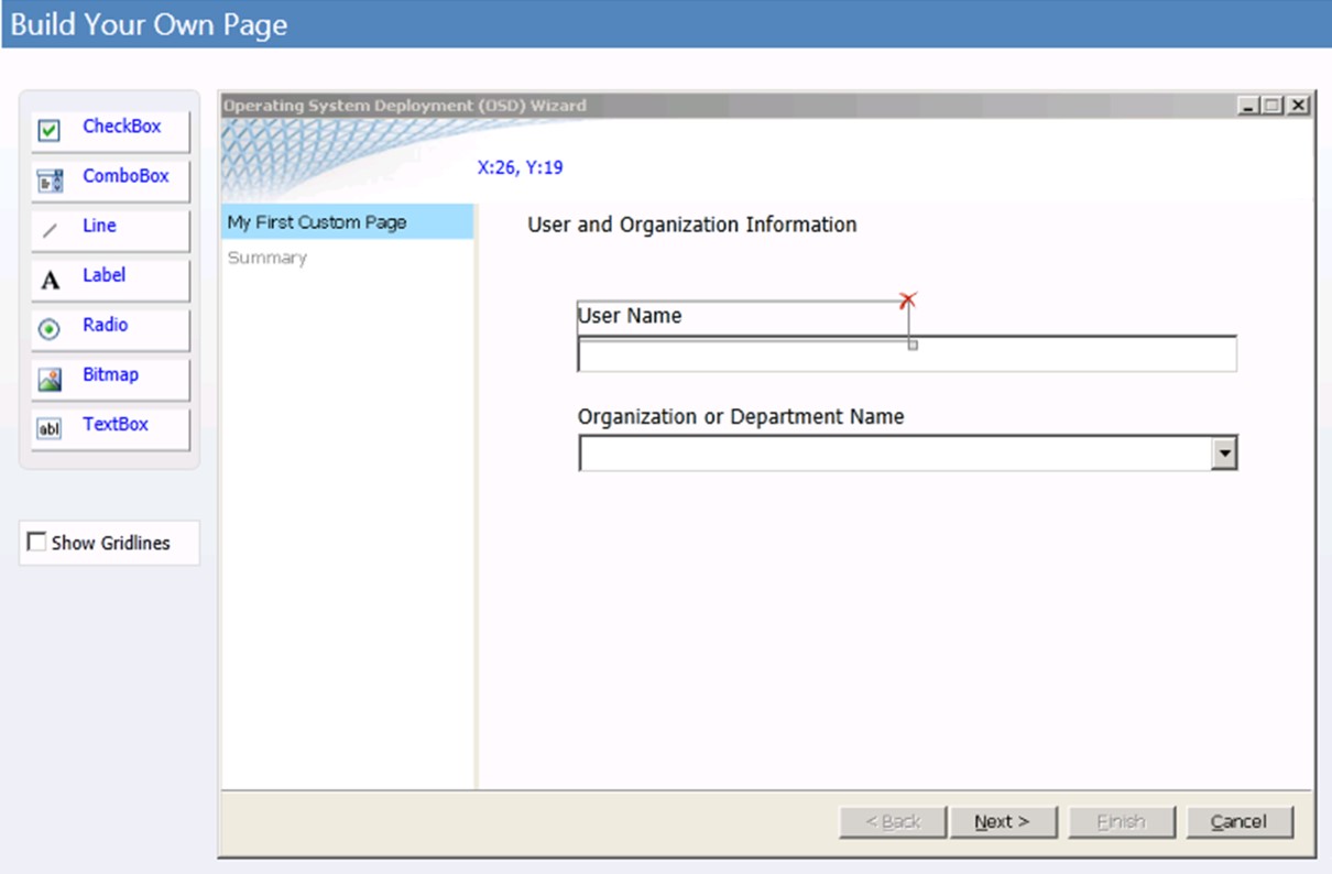
Figure 13. Example custom wizard page
To add a control to a custom wizard page
In the UDI Wizard Designer, in the Page Library, select custom_wizard_page (where custom_wizard_page is the name of the custom wizard page to which you want to add the control).
If you have not already added a custom wizard page based on the Build Your Own Page wizard page type to the Page Library, add a custom wizard page. For more information on how to add a custom wizard page based on the Build Your Own Page wizard page type to the Page Library, see Create a New Custom Wizard Page.
In the details pane, select the Configure tab.
The custom wizard page is displayed in the details pane.
In the Build Your Own Page toolbox, select toolbox_control (where toolbox_control is the type of control you want to add to the custom wizard page), and drag it to the custom wizard page.
The control is added to the custom wizard page.
Position a Control on a Custom Wizard Page
After a control has been added to a custom wizard page, you can position the control by performing one of the following tasks:
Position a control on a custom wizard page using drag and drop as described in Position a Control on a Custom Wizard Page Using Drag and Drop.
Position a control on a custom wizard page using control properties as described in Position a Control on a Custom Wizard Page Using Control Properties.
Position a Control on a Custom Wizard Page Using Drag and Drop
You can position a control on a custom wizard page using drag and drop for one of the following situations:
Initially placing the control from the Build Your Own Page to the custom wizard page
Moving the control to an approximate location on the custom wizard page
To position a control more precisely, position the control using the X and Y properties on the Layout properties of the control. For more information on positioning a control on a custom wizard page using control properties, see Position a Control on a Custom Wizard Page Using Control Properties.
To position a control on a custom wizard page using drag and drop
In the UDI Wizard Designer, in the Page Library, select custom_wizard_page (where custom_wizard_page is the name of the custom wizard page to which you want to position the control).
If you have not already added a custom wizard page based on the Build Your Own Page wizard page type to the Page Library, add a custom wizard page. For more information about how to add a custom wizard page based on the Build Your Own Page wizard page type to the Page Library, see Create a New Custom Wizard Page.
In the details pane, select the Configure tab.
The custom wizard page is displayed in the details pane.
In the details pane, select toolbox_control (where toolbox_control is the control you want to position on the custom wizard page), and then drag it to the desired location on the custom wizard page.
Tip
You can use the x and y coordinate locations displayed at the top of the custom wizard page to help you position the control.
Position a Control on a Custom Wizard Page Using Control Properties
Position a control on a custom wizard page when you want to control the placement of the control so that all your controls are aligned precisely. You position the control using the X and Y properties on the Layout properties of the control.
To position a control approximately, such as when you are doing your initial layout, do so using drag and drop. For more information on positioning a control on a custom wizard page using drag and drop, see Position a Control on a Custom Wizard Page Using Drag and Drop.
To position a control on a custom wizard page using control properties
In the UDI Wizard Designer, in the Page Library, select custom_wizard_page (where custom_wizard_page is the name of the custom wizard page to which you want to position the control).
If you have not already added a custom wizard page based on the Build Your Own Page wizard page type to the Page Library, then add a custom wizard page. For more information about how to add a custom wizard page based on the Build Your Own Page wizard page type to the Page Library, see Create a New Custom Wizard Page.
In the details pane, select the Configure tab.
The custom wizard page is displayed in the details pane.
In the details pane, select toolbox_control (where toolbox_control is the control you wish to position on the custom wizard page), and then select the Layout tab.
On the Layout tab, configure the values for the properties listed in Table 150 based on the coordinates at which you want the control to be located.
Table 150. Control Position Layout Properties
Property Description X This property controls the horizontal position of the control. Y This property controls the vertical position of the control. After the properties are configured, the control is positioned at the coordinates specified by these properties.
Change the Size of a Control on a Custom Wizard Page
Change the size of a control on a custom wizard page so that the contents of the control are properly displayed. You change the size of the control using the Width and Height properties on the Layout properties of the control.
To change the size of a control on a custom wizard page
In the UDI Wizard Designer, in the Page Library, select custom_wizard_page (where custom_wizard_page is the name of the custom wizard page to which you want to position the control).
In the details pane, select the Configure tab.
The custom wizard page is displayed in the details pane.
In the details pane, select toolbox_control (where toolbox_control is the control you wish to change in size on the custom wizard page), and then select the Layout tab.
On the Layout tab, configure the values for the properties listed in Table 151 based on the size you want the control to be.
Table 151. Control Size Layout Properties
Property Description Width This property controls the width of the control.
If the text or graphic displayed in the control is wider than the width of the control, the text or graphic is clipped and not displayed.Height This property controls the height of the control.
If the text or graphic displayed in the control is higher than the height of the control, the text or graphic is clipped and not displayed.After the properties are configured, the size of the control reflects the values in these properties.
Remove a Control from a Custom Wizard Page
Remove a control from a custom wizard page when the control is no longer needed on the custom wizard page. Once you remove a control from a custom wizard page, all Layout and Settings properties associated with the control are also removed. Once the control has been removed and the UDI Wizard configuration file has been saved, the removal cannot be undone.
Tip
If you want to undo removal of a control, close the UDI Wizard without saving changes.
To remove a control from a custom wizard page
In the UDI Wizard Designer, in the Page Library, select custom_wizard_page (where custom_wizard_page is the name of the custom wizard page from which you want to remove the control).
In the details pane, select the Configure tab.
The custom wizard page is displayed in the details pane.
In the details pane, select toolbox_control (where toolbox_control is the control you want to remove from the custom wizard page), and then select the red X in the upper right corner of the control.
The control is removed from the custom wizard page.
Edit Custom Wizard Page Control Properties
Each control that you place on your custom wizard page has properties. These properties are used to configure the appearance of the control and how the UDI Wizard processes the information the control collects.
The following types of properties are available for Build Your Own Page toolbox controls:
Layout properties. Use these properties to configure the UI characteristics of the control. Every control has Layout properties, such as the Y, X, Width, and Height properties.
For more information about the Layout properties for a specific control, see the corresponding section for each control in "UDI Build Your Own Page Toolbox Control Reference" in the MDT document, Toolkit Reference.
Settings properties. Use these properties to configure the data that is initially shown in a control (default value) and where the information collected from the user is saved. Only controls that collect information have Settings properties, such as the Task sequence variable name and Friendly display name visible in summary page properties.
For more information about the Settings properties for a specific control, see the corresponding section for each control in "UDI Build Your Own Page Toolbox Control Reference" in the MDT document, Toolkit Reference.
To edit custom wizard page control properties
In the UDI Wizard Designer, in the Page Library, select custom_wizard_page (where custom_wizard_page is the name of the custom wizard page on which you want to position the control).
In the details pane, select the Configure tab.
The custom wizard page is displayed in the details pane.
In the details pane, select toolbox_control (where toolbox_control is the control you want to position on the custom wizard page).
Select the Layout tab to configure the Layout properties.
For more information about the Layout properties for a specific control, see the corresponding sections for each control in "UDI Build Your Own Page Toolbox Control Reference" in the MDT document, Toolkit Reference.
Select the Settings tab to configure the Settings properties.
For more information about the Settings properties for a specific control, see the corresponding sections for each control in "UDI Build Your Own Page Toolbox Control Reference" in the MDT document, Toolkit Reference.
Show or Hide Custom Wizard Page Gridlines
You can show or hide gridlines on your custom wizard pages. The gridlines help you place controls so that they are aligned properly to each other.
To show or hide custom wizard page gridlines
In the UDI Wizard Designer, in the Page Library, select custom_wizard_page (where custom_wizard_page is the name of the custom wizard page on which you want to position the control).
In the details pane, select the Configure tab.
The custom wizard page is displayed in the details pane.
In the details pane, select or clear the Show Gridlines check box.
The Show Gridlines check box determines whether the gridlines are displayed on the custom wizard page. If theShow Gridlines check box is:
Selected, then the gridlines are displayed
Cleared, then the gridlines are not displayed
Verify and Test a Custom Wizard Page
After you create your custom wizard page and configure the appropriate controls, verify that your custom wizard page behaves as expected. You can verify and test your custom wizard page using the preview feature in the UDI Wizard Designer.
The preview feature allows you to visualize the user experience and make any changes to the user experience prior to performing actual deployments. You can interact with your custom wizard page as though you were the user running the UDI Wizard.
For more information on how to preview wizard pages and the wizard page sequence flow, see Preview Wizard Pages and the Wizard Page Sequence Flow.
Running the UDI Wizard
The UDI Wizard is automatically initiated when you run a UDI-based task sequence. Initiate the UDI-based task sequence automatically by using Windows Deployment Services or manually by using a deployed (advertised) task sequence in the Configuration Manager Client. Each MDT deployment scenario (New Computer, Refresh Computer, or Replace Computer) uses a different process. Initiate the deployment from Windows Deployment Services or using task sequence bootable media. The deployment process prompts for any configuration settings not already specified.
The UDI Wizard displays wizard pages based on the MDT deployment scenario you selected and the configuration options you saved in UDI Wizard configuration file (UDIWizard_Config.xml) in the Scripts folder of the MDT files package. The controls that are enabled and their default values are also controlled by the configuration options you saved in the UDI Wizard configuration file.
To run the UDI Wizard
Initiate the task sequence created using a UDI-based task sequence template and one of the following methods:
Task sequence bootable media disk using the Task Sequence Media Wizard as described in Creating Task Sequence Bootable Media in Configuration Manager.
Windows Deployment Services to start the appropriate Windows PE images that will in turn start the UDI deployment process to the target computers as described in Preparing Windows Deployment Services for UDI Deployments.
Windows PE starts, and then the Task Sequence Wizard starts.
Complete the Task Sequence Wizard by selecting the appropriate UDI-based task sequence.
At the appropriate task sequence step, the UDI Wizard starts.
Complete the UDI Wizard based on the wizard pages selected and the sequence of the wizard pages.
Tip
Ensure that you preview the user experience of the wizard pages in the UDI Wizard using the Preview feature in the UDI Wizard Designer prior to performing deployments in your production environment.
After you complete the UDI Wizard, the deployment of the new operating system begins. When the deployment process is complete, the OSD Results page is displayed just prior to the first user logging on to the target computer. For more information about how to configure the OSD Results page, see the section, "OSDResults.exe.config File Element Values", in the MDT document Toolkit Reference.
Configuring MDT Deployments
Configure MDT deployments by:
Customizing the CustomSettings.ini and Bootstrap.ini files as described in Customizing MDT Configuration Files
Customizing the MDT properties as described in Configuring the Appropriate MDT Properties
Applying the MDT properties to groups of computers as described in Applying MDT Properties to Groups of Computers
Applying the MDT properties to individual computers as described in Applying MDT Properties to Individual Computers
Configuring the MDT processing rules as described in Configuring MDT Processing Rules
Preparing disks on the target computers as described in Preparing Disks on Target Computers
Saving and restoring the user state migration data using USMT as described in Saving and Restoring User State Information
Joining target computers to AD DS domains as described in Joining Target Computers to AD DS Domains
Deploying software updates to the target computers as described in Deploying Software Updates to Target Computers
Managing device drivers in MDT deployments as described in Managing Device Drivers
Running Microsoft System Center 2012 Orchestrator runbooks from MDT as described in Running Orchestrator Runbooks
Running Windows PowerShell scripts in a task sequence as described in Running Windows PowerShell Scripts During Deployment
Applying security and compliance configuration settings using Group Policy Object Packs as described in Applying Group Policy Object Packs
Enabling participation in Windows Customer Experience Improvement Program(CEIP) and Windows Error Reporting (WER) as described in Enabling Participation in CEIP and WER
Configuring the task sequence steps that configure Windows roles and features on the target computer as described in Configuring Roles and Features Task Sequence Steps
Configuring server roles for Windows Server operating systems in MDT deployments as described in Configuring Server Role Task Sequence Steps
Copying content to the target computers for MDT deployments as described in Copying Content to the Target Computer
Creating custom scripts that integrate with the MDT deployment processes as described in Creating Custom Scripts for MDT
Customizing MDT Configuration Files
MDT is flexible and highly customizable with the MDT configuration files. The following sections contain configuration samples that demonstrate how to customize the deployment process.
Customize the MDT configuration files by:
Identifying the syntax of the CustomSettings.ini file as described in Identify the CustomSettings.ini File Syntax
Identifying the sections of the CustomSettings.ini file as described in Sections in the CustomSettings.ini File
Configuring the properties in the CustomSettings.ini file as described in Properties in the CustomSettings.ini File
Configuring subsections in the CustomSettings.ini file as described in Subsections in the CustomSettings.ini File
Configuring the CustomSettings.ini file to run user exit scripts using the UserExit directive as described in User Exit Scripts in the CustomSettings.ini File
Configuring the basic configuration settings for the CustomSettings.ini file for LTI deployments as described in Basic CustomSettings.ini File for LTI Deployments
Configuring the basic configuration settings for the CustomSettings.ini file for ZTI deployments in Configuration Manager as described in Basic CustomSettings.ini File for ZTI Deployments Using Configuration Manger
Identifying the syntax of the BootStrap.ini file as described in Identify the BootStrap.ini File Syntax
Identify the CustomSettings.ini File Syntax
The syntax of the CustomSettings.ini file is similar to many .ini files. A CustomSettings.ini file includes:
Sections
Properties
Settings
Listing 1 shows a CustomSettings.ini file customized for ZTI for Configuration Manager. For more information about the CustomSettings.ini file in Listing 1, see Basic CustomSettings.ini File for ZTI Deployments Using Configuration Manger, later in this guide.
Listing 1. CustomSettings.ini File Customized for ZTI Deployment for Configuration Manager
[Settings]
Priority=Default, MACAddress
Properties=CustomProperty

[Default]
OSInstall=Y
ScanStateArgs=/v:5 /o /c
LoadStateArgs=/v:5 /c /lac
UserDataLocation=NONE

[00:0F:20:35:DE:AC]
CustomProperty=TRUE

[00:03:FF:FE:FF:FF]
CustomProperty=FALSE
Sections in the CustomSettings.ini File
Sections are identified by brackets ([]) that surround the section name (for example, [Settings]). In Listing 1, the sections include [Settings], [Default], [00:0F:20:35:DE:AC], and [00:03:FF:FE:FF:FF].
The sections in the CustomSettings.ini file include the:
Required sections as described in Required Sections
Optional sections as described in Optional Sections
Required Sections
Only the [Settings] section is required. All other sections are optional. The MDT scripts require the [Settings] section in CustomSettings.ini to locate the reserved properties (Priority and Properties).
Optional Sections
You use the optional sections in the CustomSettings.ini file to assign a group of configuration settings to:
A group of computers. In Listing 1, the configuration settings in the
[Default]section are applied to more than one computer. For more information, see Applying MDT Properties to Groups of Computers, later in this guide.An individual computer. In Listing 1, the configuration settings in the
[00:0F:20:35:DE:AC]and[00:03:FF:FE:FF:FF]sections are applied to the corresponding computer (in this case, identified by the media access control [MAC] address of the target computer). For more information, see Applying MDT Properties to Individual Computers, later in this guide.
Properties in the CustomSettings.ini File
Properties are variables to which values must be assigned. Properties are followed by an equal sign (=). The scripts scan the CustomSettings.ini file to locate the properties.
The types of properties that you can use in deploying target computers include properties that are:
Automatically declared in ZTIGather.wsf. These predefined properties are declared in the ZTIGather.wsf code and are documented in the MDT document Toolkit Reference. In addition, the ZTIGather.wsf file automatically sets the values for these properties. These properties are not configured in CustomSettings.ini and should be treated as read only.
Declared in the ZTIGather.xml file. These predefined properties are listed in the ZTIGather.xml file and are documented in the MDT document Toolkit Reference. The ZTIGather.wsf file retrieves these properties by scanning the ZTIGather.xml file. Divide the properties in this file into properties that:
ZTIGather.wsf automatically assigns values to. ZTIGather.wsf automatically sets the values for these properties, which must be treated as read only.
Must be assigned values in CustomSettings.ini. Ensure that the value for any property to be used is set in CustomSettings.ini and is considered modifiable.
Declared in the Properties property. These are custom properties that can be declared, and they are in addition to the properties automatically declared in ZTIGather.wsf and in ZTIGather.xml.
The way you use properties for ZTI and LTI are identical. However, some properties are unique to ZTI or LTI deployment. Like ZTI deployments, LTI deployments also have unique properties. Most of the LTI-specific properties relate to the Deployment Wizard (such as SkipAdministratorPassword, SkipCapture, or SkipUserData). Although these properties use the same syntax as other properties, the reserved properties perform specific functions in the deployment processing rules.
Note
Property values must be specified in upper case so that the deployment scripts can properly identify them—for example, YES, TRUE, or FALSE. This is true for property values specified in the CustomSettings.ini file, BootStrap.ini file, and MDT DB.
Configure the CustomSettings.ini file by:
Configuring the Priority reserved property as described in Priority Reserved Property
Configuring the Properties reserved property as described in Properties Reserved Property
Configuring the values for properties as described in Values in the CustomSettings.ini File
Priority Reserved Property
The Priority reserved property determines the sequence and section in which you can find configuration values. Each section is searched in the order specified. When a property value is found, the remaining sections are not used for that property. In Listing 1, the [Default] section is parsed first, and then the section that corresponds to the MAC address of the target computer (in this case, [00:0F:20:35:DE:AC] or [00:03:FF:FE:FF:FF]).
Table 152 lists the types of sections that you can reference in the Priority property.
Table 152. Section Types for the Priority Property
| Type | You can base sections on |
|---|---|
| MDT properties | Any property known MDT. For example, specifying the HostName property causes MDT to scan for a section with the target computer host name. Other properties, like MACAddress, can result in multiple section names being checked (because a computer can have multiple MAC addresses). |
| Literal section name | A literal name that you specify in the Priority property. For example, if MySection is included in the Priority property, MDT would search for properties not previously found in the [MySection]section. |
| Indirect reference | A literal name that references a section, which in turn references other sections. For example, if the DefaultGateway property is included in the Priority property, MDT would search for the [DefaultGateway] section. If the [DefaultGateway] section references other sections (based on the IP address of the default gateway), this is an example of an indirect reference. For an example of indirect reference using the DefaultGateway property, see "Example: Computer Groupings Selected by Woodgrove Bank" in Select the Method for Grouping Computers. |
Properties Reserved Property
The Properties reserved property (shown in Listing 1) defines any custom, user-defined properties to be used in the deployment. These user-defined properties are located by ZTIGather.wsf script in the CustomSettings.ini file (or configuration database). These properties are in addition to the predefined properties in MDT.
In Listing 1, CustomProperty is a user-defined property, and ScanStateArgs is a predefined property. For a list of the predefined properties in MDT, see the section, "Properties", in the MDT document Toolkit Reference.
You can also define custom properties to which you can assign multiple values by adding numerical suffixes, such as ListProperty001, ListProperty002, and so on. You create these types of custom properties by adding "(*)" to the end of the property name. For example, ListProperty(*) defines the custom property as a list of property values instead of a single-valued property. Consider the following excerpt from a CustomSettings.ini file in which ListProperty(*) is defined:
[Settings]
Priority=Default
Property=CustomProperty, ListProperty(*)

[Default]
CustomProperty=TRUE
ListProperty001=New York City
ListProperty002=Chicago
Values in the CustomSettings.ini File
Values are the configuration settings assigned to the properties. Values are preceded by an equal sign (=). The scripts scan the CustomSettings.ini file to locate the values. In Listing 1, the value assigned to the LoadStateArgs property is:
/v:5 /c /lac
Note
the CustomSettings.ini file is different from traditional INI files in that you do not place quotation marks around values, even if the value contains spaces.
Subsections in the CustomSettings.ini File
You can create subsections in the Customsettings.ini file based on the value of a property using the Subsection directive. The value of the Subsection directive can be used to dynamically reference subsections that can be used to group configuration settings.
Listing 2 illustrates an excerpt of a CustomSettings.ini file that uses the Subsection directive to dynamically reference subsections based on the computer model, which is specified in the Model property.
Listing 2. Using the Subsection Directive to Dynamically Reference Subsections in the CustomSettings.ini File
[Settings]
Priority=Make, Default

[Default]

[Contoso Computer Corporation]
Subsection=Contoso-%Model%

[Contoso-MDT 6600]
Packages001=XXX00009:Program9
Packages002=XXX0000A:Program10

[Contoso-MDT 2431]
Packages001=XXX00003:Program2
Packages002=XXX00003:Program4
In Listing 2, the Priority line contains the Make property, which is used to references subsections based on the value of the Make property. The "Contoso Computer Corporation" subsection is referenced when the value of the Make property is equal to "Contoso Computer Corporation".
The "Contoso Computer Corporation" subsection contains a Subsection line that references other subsections based on the value of the Model property. In this example, the "Contoso-MDT 6600" and "Contoso-MDT 2431" sections will be processed by MDT depending on the value of the Model property.
User Exit Scripts in the CustomSettings.ini File
A user exit script is effectively a function library that can be called during the processing of the CustomSettings.ini file using the UserExit directive. A user exit script contains one or more functions that can be called during the process of the CustomSettings.ini file.
A user exit script is called by specifying the UserExit directive and assigning the property name of the script to be called—for example, UserExit=TrimAssetTag.vbs. A function within the user exit script is called by specifying the name of a function enclosed in the # characters. For example, if the user exit script contains a function called TrimAssetTag(), it would be called by specifying #TrimAssetTag()#.
Parameters can be passed to the function in the user exit script in the usual way by specifying the parameter while calling the function. For example, to pass the variable %ASSETTAG% to the function TrimAssetTag(), the function would be called by specifying #TrimAssetTag("%ASSETTAG%")#.
The value returned by the function can be assigned to a variable by assigning the function to that variable. For example, to take the asset tag of a computer and trim it using the function TrimAssetTag(), and to then reassign the trimmed asset tag to the variable AssetTag, the CustomSettings.ini file would read AssetTag=#TrimAssetTag("%ASSETTAG%")#.
An example of how this could be used is to determine the task sequence to be run based on a rule that sets the TaskSequenceID property. Listing 3 is an example user exit script that determines the task sequence to be run based on the amount of available RAM. This script also uses the ZTIUtility logging class.
Listing 3. Example User Exit Script
Function UserExit(sType, sWhen, sDetail, bSkip)
  UserExit = Success
End Function

Function SetTaskSequence(vMemory)

  oLogging.CreateEntry "UserExit - Determining Task " & _
    "Sequence to run based on available RAM", LogTypeInfo

  If vMemory <= 2048 Then
    SetTaskSequence = "Win7_X86"
    oLogging.CreateEntry "UserExit - Available RAM: " & _
      vMemory & ". Selecting Win7_X86 TS.", LogTypeInfo
  Else
    SetTaskSequence = "Win8_X86"
    oLogging.CreateEntry "UserExit - Available RAM: " & _
      vMemory & ". Selecting Win8_X86 TS.", LogTypeInfo
  End If
End Function
The user exit script should be placed in the Scripts folder on the deployment share (for example, D:\Production Deployment Share\Scripts).
To create the user exit script
Create and test the custom script to be used.
Locate the MDT Scripts folder (for example, D:\Production Deployment Share\Scripts).
Copy the custom script to the Scripts folder.
With the user exit script added to the deployment share (in this case, Z-RAMTest.wsf), it must then be referenced in the CustomSettings.ini file for the deployment share so it is called during deployment.
To call the user exit script from CustomSettings.ini
Select Start, and then point to All Programs. Point to Microsoft Deployment Toolkit, and then select Deployment Workbench.
In the Deployment Workbench console tree, go to Deployment Workbench/Deployment Shares/deployment_share (where deployment_share is the name of the deployment share to configure).
In the Actions pane, select Properties.
Select the Rules tab to display the CustomSettings.ini file.
Add sections to UserExit.vbs to call the required functionality using the principles described in the previous section. An example CustomSetting.ini file is shown in Listing 4.
Select OK to submit the changes.
In the details pane, select deployment_share (where deployment_share is the name of the deployment share to configure).
In the Actions pane, select Update Deployment Share.
The Update Deployment Share Wizard starts.
On the Options page, select Optimize the boot image updating process, and then select Next.
On the Summary page, verify the details are correct, and then select Next.
On the Confirmation page, select Finish.
Another common use for the user exit script is to dynamically set the computer name from known MDT properties such as SerialNumber, Model, or Product.
Listing 4. Example CustomSettings.ini for Calling the User Exit Script
[Settings]
Priority=Default

[Default]
OSInstall=Y
TaskSequenceID=#SetTaskSequence("%MEMORY%")#
UserExit=Z-RAMTest.vbs

UserDataLocation=NONE
SkipCapture=YES
SkipAdminPassword=NO
SkipProductKey=YES
Basic CustomSettings.ini File for LTI Deployments
For LTI deployments, the Deployment Workbench uses a template version of the CustomSettings.ini file (stored in installation_folder\Templates, where installation_folder is the folder in which MDT is installed) as a basis for a customized version of CustomSettings.ini. The template version of the CustomSettings.ini file is illustrated in Listing 5. The template version in Listing 5 does not contain sufficient settings to successfully deploy Windows to a target computer. However, the file will be further customized using the Deployment Workbench.
Listing 5. Unmodified CustomSettings.ini File in the Templates Folder
[Settings]
Priority=Default
Properties=MyCustomProperty

[Default]
OSInstall=Y
ScanStateArgs=/v:5 /o /c
LoadStateArgs=/v:5 /c /lac
The New Deployment Share Wizard in the Deployment Workbench modifies this template of the CustomSettings.ini file based on the responses provided. Listing 6 shows the customized version of the CustomSettings.ini file after completing the New Deployment Share Wizard.
Listing 6. Customized CustomSettings.ini File Modified by the Deployment Workbench
[Settings]
Priority=Default
Properties=MyCustomProperty

[Default]
OSInstall=Y
ScanStateArgs=/v:5 /o /c
LoadStateArgs=/v:5 /c /lac
UserDataLocation=NONE
SkipCapture=NO
SkipAdminPassword=YES
SkipProductKey=YES
The CustomSettings.ini file in Listing 6 contains the property values for all the target computers to be migrated using this version of the file. This version of the file contains no values unique to a specific target computer. For LTI, the target computer-specific configuration values are manually provided during the installation process.
Table 153 explains the properties and corresponding values used in Listing 6.
Table 153. Explanation of CustomSettings.ini Properties in Listing 6
| Line in CustomSettings.ini | Purpose |
|---|---|
[Settings] |
Indicates the start of the [Settings] section. |
Priority=Default |
Establishes the sequence in which the process parses subsections to locate values for the variables. In this example, the [Default] section is the only subsection that is parsed for variables. |
Properties=MyCustomProperty |
Indicates any additional properties to locate. The properties listed here are in addition to the properties listed in ZTIGather.xml. ZTIGather.wsf parses ZTIGather.xml to obtain a list of the properties. |
[Default] |
Indicates the start of the [Default] section. |
OSInstall=Y |
Indicates that the computer is supposed to perform an operating system deployment. |
ScanStateArgs=/v:5 /o /c |
Parameters passed to the Scanstate.exe tool in the USMT. These parameters are passed to Scanstate.exe during state capture. |
LoadStateArgs=/v:5 /c /lac |
Parameters passed to the Loadstate.exe tool in the USMT. These parameters are passed to Loadstate.exe during state restore. |
UserDataLocation=NONE |
Indicates where the user state migration data should be saved. The value NONE indicates that the user state migration data should not be saved. Indicates where the user state migration data should be saved. The value NONE indicates that the user state migration data should not be saved. |
SkipCapture=YES |
Indicates whether the Specify whether to prompt for image capture page in the Deployment Wizard is displayed. If the property is set to YES, the wizard page is skipped and not displayed. Indicates whether the Specify whether to prompt for image capture page in the Deployment Wizard is displayed. If the property is set to YES, the wizard page is skipped and not displayed. |
SkipAdminPassword=YES |
Indicates whether the Allow user to set Administrator Password page in the Deployment Wizard is displayed. If the property is set to YES, the wizard page is skipped and not displayed. |
SkipProductKey=YES |
Indicates whether the Allow user to specify a product key page in the Deployment Wizard is displayed. If the property is set to YES, the wizard page is skipped and not displayed. |
For more information on the individual properties, see the corresponding reference section in the MDT document Toolkit Reference.
Basic CustomSettings.ini File for ZTI Deployments Using Configuration Manger
For ZTI deployments using Configuration Manager, the Deployment Workbench uses a template version of the CustomSettings.ini file (stored in installation_folder\Templates, where installation_folder is the folder in which MDT is installed) as a basis for a customized version of CustomSettings.ini. The template version of the CustomSettings.ini file is illustrated in Listing 7. The template version in Listing 7 does not contain sufficient settings to successfully deploy Windows to a target computer. However, the file will be further customized using the Deployment Workbench.
Listing 7. Unmodified CustomSettings.ini File in the Templates Folder
[Settings]
Priority=Default
Properties=MyCustomProperty

[Default]
OSInstall=Y
ScanStateArgs=/v:5 /o /c
LoadStateArgs=/v:5 /c /lac
The New Deployment Share Wizard in the Deployment Workbench modifies this template version of the CustomSettings.ini file based on the responses provided. Listing 8 shows the customized version of the CustomSettings.ini file after completing the New Deployment Share Wizard.
Listing 8. Customized CustomSettings.ini File Modified by the Deployment Workbench
[Settings]
Priority=Default
Properties=MyCustomProperty

[Default]
OSInstall=Y
ScanStateArgs=/v:5 /o /c
LoadStateArgs=/v:5 /c /lac
UserDataLocation=NONE
The CustomSettings.ini file shown in Listing 8 contains the property values for all of the target computers to be deployed using this version of the file. This version of the file contains no values that are unique to a specific target computer.
For ZTI using Configuration Manager, the Create MDT Task Sequence Wizard copies an unmodified version of the CustomSettings.ini template with no modifications to the file. Modify the version of the template in the package source folder that you specified in Package source to be created on the MDT Package wizard page in the Create MDT Task Sequence Wizard as described in Create ZTI Task Sequences Using the Create MDT Task Sequence Wizard in Configuration Manager.
Modify this version of the CustomSettings.ini file to include the target computer-specific configuration values. After modifying the file, update the distribution points for the Microsoft Deployment Files package so that the changes are available to the task sequences. Listing 9 shows a modified version of the CustomSettings.ini file, which includes target computer-specific settings.
Listing 9. Customized CustomSettings.ini File with Target Computer Settings
[Settings]
Priority=Default, MACAddress
Properties=MyCustomProperty

[Default]
OSInstall=Y
ScanStateArgs=/v:5 /o /c
LoadStateArgs=/v:5 /c /lac
UserDataLocation=NONE

[00:0F:20:35:DE:AC]
MyCustomProperty=TRUE

[00:03:FF:FE:FF:FF]
MyCustomProperty=FALSE
Table 154 explains the properties and corresponding values used in Listing 9.
Table 154. Explanation of CustomSettings.ini Properties in Listing 9
| Line in CustomSettings.ini | Purpose |
|---|---|
[Settings] [Settings] |
Indicates the start of the [Settings] section. |
Priority=Default, MACAddress |
Establishes the sequence in which the process parses subsections to locate values for the variables. In this example, the [Default] section is parsed first, and then the section that corresponds to the MAC address of the target computer (MACAddress) is parsed. The sections for the target computers ([00:0F:20:35:DE:AC]and [00:03:FF:FE:FF:FF]) contain computer-specific settings. Establishes the sequence in which the process parses subsections to locate values for the variables. In this example, the [Default] section is parsed first, and then the section that corresponds to the MAC address of the target computer (MACAddress) is parsed. The sections for the target computers ([00:0F:20:35:DE:AC]and [00:03:FF:FE:FF:FF]) contain computer-specific settings. |
Properties=MyCustomProperty |
Indicates any additional properties to locate. The properties listed here are in addition to the properties listed in ZTIGather.xml. ZTIGather.wsf parses ZTIGather.xml to obtain a list of the properties. |
[Default] |
Indicates the start of the [Default] section. |
OSInstall=Y |
Indicates whether the target computer is authorized to have the operating system installed. |
ScanStateArgs=/v:5 /o /c |
Parameters passed to the Scanstate.exe tool in the USMT. These parameters are passed to Scanstate.exe during the State Capture Phase. |
LoadStateArgs=/v:5 /c /lac |
Parameters passed to the Loadstate.exe tool in the USMT. These parameters are passed to Loadstate.exe during state restore. |
UserDataLocation=NONE |
Indicates where the user state migration data should be saved. The value NONE indicates that the user state migration data should not be saved. |
[00:0F:20:35:DE:AC] |
Section that contains all the properties and settings specific to the target computer with the matching MAC address. In this sample, the target computer has a MAC address of [00:0F:20:35:DE:AC]. |
[00:03:FF:FE:FF:FF] |
Section that contains all the properties and settings specific to the target computer with the matching MAC address. In this sample, the target computer has a MAC address of [00:03:FF:FE:FF:FF]. |
For more information on the individual properties, see the corresponding reference section in the MDT document Toolkit Reference.
Identify the BootStrap.ini File Syntax
In LTI deployments, use the BootStrap.ini file to specify property settings before accessing the CustomSettings.ini file. Use the BootStrap.ini file to provide distribution point information, logon credentials, and Windows PE keyboard locale settings. The properties configured in BootStrap.ini help the MDT scripts locate the appropriate MDT distribution share.
The syntax of the BootStrap.ini file is identical to the CustomSettings.ini file. The BootStrap.ini file contains a subset of the properties used in CustomSettings.ini as follows:
DeployRootNote
Ensure that the DeployRoot property is specified in the BootStrap.ini file, as the LTI deployment process will not be able to locate the CustomSettings.ini file in the deployment share. If not configured correctly, errors and warnings are displayed when running the Deployment Wizard.
SkipBDDWelcomeUserDomainUserIDUserPasswordKeyboardLocaleFor more information about each of these properties, see the corresponding section in the MDT document Toolkit Reference.
The Deployment Workbench creates the BootStrap.ini file when you create a deployment share. After the initial creation, make all further customizations manually.
Listing 10 shows the BootStrap.ini file that the Deployment Workbench creates automatically for a deployment share. You may need to customize the BootStrap.ini file in Listing 10.
Listing 10. BootStrap.ini File As Created by the Deployment Workbench for Deployment Shares
[Settings]
Priority=Default

[Default]
DeployRoot=\\NYC-MDT-01\Distribution$
Configuring the Appropriate MDT Properties
MDT uses wizards to create and manage configuration files. For more information about the standard MDT configuration files, CustomSettings.ini and BootStrap.ini, see Customizing MDT Configuration Files. However, you can customize configuration files to meet the needs of your organization.
Before configuring the deployment process, select the properties to reference from the predefined or user-defined properties. The properties selected must include all the configuration settings to be supplied during the deployment process.
For ZTI deployments using Configuration Manager, provide all configuration settings required to deploy the target operating system. For LTI deployments, provide a subset of the configuration settings that are provided automatically; the remainder of the settings can be provided manually during the deployment process.
The MDT process occurs in the phases defined in the TS.xml file. The Task Sequencer parses the TS.xml file to identify the appropriate sequence for performing the deployment process. The phases defined in the TS.xml file include:
Validate Phase. Performs validation checks to make sure that the operating system installation can proceed; specifically blocks installation on server operating systems.
State Capture Phase. Gathers information from the configuration file, databases, and the local machine to determine how the image installation process should proceed, including whether there is enough space to do a local USMT state backup. The scripts also invoke the USMT Scanstate.exe command as appropriate.
Preinstall Phase. Confirms that the necessary information has been gathered in the State Capture Phase for the Refresh Computer scenario. In the New Computer and Replace Computer scenarios, the script gathers the necessary information in this phase, because these scenarios do not perform the State Capture Phase. Also, a backup of the computer can be optionally performed for the Refresh Computer scenario.
Install Phase. Installs the target operating system on the target computers.
Post Install Phase. Updates the Unattend.xml with information gathered in the previous custom actions based on the operating system being deployed.
State Restore Phase. Invokes the USMT Loadstate.exe command to restore the user state that was previously backed up.
The TS.xml file identifies the appropriate steps in each phase based on each type of deployment scenario (Refresh Computer, Replace Computer, and New Computer). Select the properties required during each phase of the deployment process.
For more information on each of the properties used in each phase, see the section, "Properties", in the MDT document Toolkit Reference.
Applying MDT Properties to Groups of Computers
Whenever possible, use group-based rules to apply most computer configuration settings. Group-based rules allow the same configuration settings to be applied to a group of client computers. After applying group-based rules, you can supply computer-specific configuration settings using computer-based rules.
Apply properties to groups of computers by performing the following steps:
Select the method of grouping multiple computers as described in Select the Method for Grouping Computers.
Apply the properties to the groupings of computers as described in Apply the Properties to the Groups.
Select the Method for Grouping Computers
Different methods can be used to group client computers. After determining how to group the computers, select the appropriate properties to help group them.
Using the processing rules in MDT, group computers based on any property that might be applied to a group of computers (such as Make, Model, or DefaultGateway). Table 155 lists methods of grouping computers, a description of the method, and the properties that can be used to group the computers.
Table 155. Methods for Grouping Computers
| Grouping method | Description | Properties |
|---|---|---|
| Geographically | Group configuration settings based on resources located within a geographic region (such as a shared folder on a computer within a geographic region). | DefaultGateway |
| Target computer hardware attributes | Group configuration settings based on hardware attributes (such as the make of the computer or processor architecture of the target computer). | ArchitectureCapableArchitectureMake |
| Target computer software attributes | Group configuration settings based on hardware attributes (such as the operating system version of the target computer). | OSVersion |
| Default attributes | Apply configuration settings to all target computers when the properties are not in other sections. | Default |
In most instances, computer groupings can be nested. For example, you can use the DefaultGateway property to designate the IP subnets on which a computer resides within a geographic location. Define locations using the user-defined properties in the [DefaultGateway] section, as shown in Listing 11.
Note
A variety of methods can be used to group computers by hardware configuration, and the script will search for the substituted value regardless. For instance, if you specify Priority=Make, the script substitutes the value for Make that it determines through a Windows Management Instrumentation (WMI) call and will look for the corresponding section—for example, [Dell Computer Corporation].
Example: Computer Groupings Selected by Woodgrove Bank
Listing 11 shows an example of how the fictional company, Woodgrove Bank, used [DefaultGateway] to designate the configuration settings for a specific location. Three subnets (172.16.0.3, 172.16.1.3, and 172.16.2.3) reside within the NYC location. A separate section, [NYC], includes the configuration settings specific to the NYC location. Similar sections exist for the DALLAS and WASHINGTON locations. This is a special case that allows multiple default gateways to point to the same section. In many environments, a one-to-one mapping might be expected between the [DefaultGateway] section and a corresponding section.
Listing 11. Using [DefaultGateway] to Designate Location-Specific Configuration Settings
[Settings]
Priority=DefaultGateway

[DefaultGateway]
172.16.0.3=NYC
172.16.1.3=NYC
172.16.2.3=NYC
172.16.111.3=DALLAS
172.16.112.3=DALLAS
172.16.116.3=WASHINGTON
172.16.117.3=WASHINGTON

[NYC]
UDShare=\\NYC-AM-FIL-01\MigData
SLShare=\\NYC-AM-FIL-01\Logs
Packages1=NYC00010-Install
Packages2=NYC00011-Install
Administrator1=WOODGROVEBANK\NYC Help Desk Staff

[DALLAS]
UDShare=\\DAL-AM-FIL-01\MigData
SLShare=\\DAL-AM-FIL-01\Logs
Administrator1=WOODGROVEBANK\DAL Help Desk Staff
Apply the Properties to the Groups
After identifying how to group configuration settings, determine which properties and corresponding configuration settings to apply to each group. Properties that can be grouped are those you can apply to multiple computers.
Some examples of properties that are typically applied to groups of computers include:
BackupDir
BackupShare
CaptureGroups
ComputerBackupLocation
Packages
SLShare
UDDir
UDShare
UDProfiles
Properties that are not applied to groups of computers are those specific to a particular computer. Examples of properties that are not appropriate to apply to groups of computers include:
OSDAdapter0IPAddress
OSDNewMachineName
Example: Group-based Configuration Settings Selected by Woodgrove Bank
Listing 11 showed an example in which Woodgrove Bank selects group-based configuration settings:
In the NYC and DALLAS locations,
UDShare,SLShare, andAdministrator1are specified for each location.The servers that
UDShareandSLSShare(NYC-AM-FIL-01andDAL-AM-FIL-01) reference are within each respective location.The Administrator accounts that
Administrator1(WOODGROVEBANK\NYC Help Desk StaffandWOODGROVEBANK\DAL Help Desk Staff) reference are unique to each respective location.In NYC, location-specific packages are designated by
Packages1andPackages2.
Applying MDT Properties to Individual Computers
After determining the groupings of target computers and configuration settings to be applied to each group, determine the method for identifying individual computers and the configuration settings to assign to each computer. The rules for target computers allow the override or augmentation of group-based processing rules based on the priority of the computer-based rules.
For more information about determining the priority of processing rules, see Priority Reserved Property, earlier in this guide.
Whenever possible, use group-based rules for most client computer configuration settings. Group-based rules allow the same configuration settings to be applied to a group of computers. After applying group-based rules, you can apply computer-specific configuration settings using computer-based rules.
As when grouping computers, more than one method is available for identifying individual computers. After selecting the method for identifying an individual target computer, select the appropriate properties.
The processing rules allow the identification of computers based on any property that you might apply to an individual of computer (such as AssetTag, MACAddress, UUID, and so on).
Table 156 lists the methods of identifying individual computers, a description of the method, and the properties that you can use to identify the individual computers.
Table 156. Methods for Identifying Individual Computers
| Identification method | Description | Properties |
|---|---|---|
| Target computer hardware attributes | Identify the target computer using the hardware configuration. | AssetTag, MACAddress, SerialNumber, UUID, Product, Make, and Model |
| Target computer software attributes | Identify the target computer using the software or firmware configuration. | OSVersion, IsServerOS, and OSSKU |
| Target computer user-defined attributes | Identify the target computer using attributes that are assigned to the computer but not part of the hardware or software configuration. | AssetTag SerialNumber |
Example: Computer Identification Method Selected by Woodgrove
Listing 12 shows an example of how Woodgrove Bank identified computer-based configuration settings. In this instance, Woodgrove used the MAC address of the computer to identify the corresponding configuration settings for the computer (for example, 00:03:FF:CB:4E:C2and00:0F:20:35:DE:AC). The configuration settings for each computer are listed immediately after the section that corresponds to the computer's MAC address.
Listing 12. How Woodgrove Identified Client Computers
[00:03:FF:CB:4E:C2]
ComputerName=WasW2K
OverRideProductKey=TTTTT-VVVVV-WWWWW-XXXXX-YYYYY

[00:0F:20:35:DE:AC]
ComputerName=HPD530-1
OverRideProductKey=AAAAA-BBBBB-CCCCC-DDDDD-EEEEE

[00:03:FF:FE:FF:FF]
ComputerName=BVMXP
OverRideProductKey=11111-22222-33333-44444-55555
Example: Computer-based Configuration Settings Selected by Woodgrove
Listing 12 also shows the computer-based configuration settings that Woodgrove Bank selected. Table 157 lists the computer-specific configuration settings applied to each computer.
Table 157. Woodgrove Client Computers and the Corresponding Configuration Settings
| Target computer | Settings and description |
|---|---|
[00:03:FF:CB:4E:C2] |
ComputerName is the name of the computer after deployment—in this case, WasW2K.OverRideProductKey is the product key to be assigned to the computer—in this case, TTTTT-VVVVV-WWWWW-XXXXX-YYYYY. |
[00:0F:20:35:DE:AC] |
ComputerName is the name of the computer after deployment—in this case, HPD530-1.OverRideProductKey is the product key to be assigned to the computer—in this case, AAAAA-BBBBB-CCCCC-DDDDD-EEEEE. |
[00:03:FF:FE:FF:FF] |
ComputerName is the name of the computer after deployment—in this case, BVMXP.OverRideProductKey is the product key to be assigned to the computer—in this case, 11111-22222-33333-44444-55555. |
Configuring MDT Processing Rules
MDT scripts configure computer settings based on rules and configuration settings stored in the CustomSettings.ini file or in the MDT DB. Configure the MDT processing rules by completing the following tasks:
Configure the processing rules as described in Configure the Rules in the CustomSettings.ini File.
Configure the processing rules as described in Configure the Rules in the MDT DB.
Configure the Rules in the CustomSettings.ini File
Configure rules in the CustomSettings.ini file. The template version of the CustomSettings.ini file, along with the organization's rules, becomes the customized CustomSettings.ini file.
For LTI deployments, configuring group-based settings might be sufficient, because computer-specific settings can be provided during the MDT installation process. For ZTI deployments using Configuration Manager, add configuration settings unique to a specific client computer, because ZTI assumes that all configuration settings necessary for deployment are configured in advance. These configuration settings can be in addition to or instead of the group-based rules.
Configure the Rules in the MDT DB
Use the Deployment Workbench to configure the rules for LTI and ZTI deployments in the MDT DB. The benefits of using the MDT DB include:
It has a more generic version of CustomSettings.ini. Storing the configuration settings in the MDT DB removes most of the detail from the CustomSettings.ini file. This change helps make the CustomSettings.ini file more generic so that you can use the same file in multiple deployment shares.
It is a centralized repository for all property configuration settings. Centralizing the configuration for all property settings ensures consistency across all deployment shares.
For information about the MDT DB and using it to perform deployments, see Performing Deployments Using the MDT DB.
Preparing Disks on Target Computers
Prior to deploying the target operating system on a target computer, the MDT deployment process prepares the disks on the target computer for deployment. The disk-preparation process includes the following steps:
Create partitions on one or more drives on the target computers.
Format one or more partitions on the target computers.
Prepare the disks on the target computers for BitLocker.
Disk preparation occurs during the State Capture and Preinstall phases in the MDT deployment process. The disk-preparation step completed in the State Capture Phase is the disabling of BitLocker on the target computer. The disk-preparation steps completed in the Preinstall Phase create and format the partitions on the target computer.
To prepare the disks on target computers in MDT
Review the default partition configuration created by MDT as described in Review the Default Partition Configuration Created by MDT.
Prepare for deployment to virtual hard disks (VHDs) with native boot as described in Prepare for Deployment to Virtual Hard Disks with Native Boot.
Configure task sequence steps based on the Create Virtual Hard Disk task sequence step type as described in Configure the Create VHD Disk Task Sequence Step Type.
Deploy to computers that support the Unified Extensible Firmware Interface specification as described in Deploy to Computers with UEFI.
Review the task sequence steps used for saving and restoring user state information as described in Configure Disk Preparation Task Sequence Steps.
Configure the MDT properties used in saving and restoring user state information as described in Configure Disk Preparation Properties.
Review the Default Partition Configuration Created by MDT
The MDT deployment processes automatically create the necessary disk partitions to take full advantage of the features provided by the target computer and operating system. By default, MDT creates the partition configuration for BIOS-based computers as described in Table 158.
Table 158. Default Partition Configuration Created by MDT for BIOS-based Computers
| Partition | File system | Size | Description |
|---|---|---|---|
| BDEDrive | NTFS | 512 MB | Unencrypted partition used for starting Windows, also known as the system partition. This partition is used to initially start Windows until BitLocker is loaded and the operating system drive can be read. This partition can also be shared with the recovery partition. |
| OSDisk | NTFS | Remaining space | Partition on which Windows is located, also known as the operating system drive. If BitLocker is used, this is the partition that is encrypted. |
By default, MDT creates the partition configuration for UEFI-based computers as described in Table 159.
Table 159. Default Partition Configuration Created by MDT for UEFI-based Computers
| Partition | File system | Size | Description |
|---|---|---|---|
| Description | FAT32 | 512 MB | Unencrypted partition used for starting Windows. For more information, see Deploy to Computers with UEFI. This partition can also be shared with the recovery partition. |
| MSR | Unformatted | 128 MB | The Microsoft Reserved Partition (MSR) is a partition on a data storage device that is labeled with a GUID equal to E3C9E316-0B5C-4DB8-817D-F92DF00215AE. The containing storage device has to use the new GUID Partition Table (GPT) format, not the traditional master boot record (MBR) partition table format.An MSR partition is required on every GPT disk and should be created as the disk is initially partitioned. It should be located after the EFI System Partition (ESP) and any OEM service partitions, but—most importantly—the first data partition must immediately follow it. |
| OSDisk | NTFS | Remaining space | Partition on which Windows is located, also known as the operating system drive. If BitLocker is used, this is the partition that is encrypted. |
In addition to the default MDT partition configurations, you can create custom partition configurations. For example, the default MDT partition configurations do not include other utility partitions or recovery images. For more information, see Understanding Disk Partitions.
Prepare for Deployment to Virtual Hard Disks with Native Boot
Native boot allows VHDs to run on a computer without a VM or hypervisor.
Note
Only LTI supports deployment to VHDs with native boot.
Native VHD boot has the following dependencies:
The local disk must have at least two partitions: a system partition that contains the Windows boot environment files and Boot Configuration Data (BCD) store and a partition to store the VHD file.
The local disk partition that contains the VHD file must have enough free disk space for expanding a dynamic VHD to its maximum size and for the page file created when booting the VHD. The page file is created outside of the VHD file, unlike in a VM, where the page file is contained inside the VHD.
You can create LTI task sequences based on the following LTI task sequence templates to deploy to VHDs with native boot:
Deploy to VHD Client Task Sequence. Select this LTI task sequence template to deploy Windows in a VHD with native boot.
Deploy to VHD Server Task Sequence. Select this LTI task sequence template to deploy Windows Server in a VHD with native boot.
These tasks sequences contain the following task sequence steps, which are used to perform deployment to VHDs:
Create VHD Disk. The step creates the VHD file after the physical partition has been created and formatted. For more information about this task sequence step, see Configure the Create VHD Disk Task Sequence Step Type.
Format and Partition VHD. This step formats the .vhd file and is built using the Format and Partition Disk task sequence step type. For more information about task sequence step type, see Configure Disk Preparation Task Sequence Steps.
Clear OSDDiskIndexVariable. This step clears the OSDDiskIndexVariable task sequence variable that was set during the Create VHD Disk task sequence step. Clearing the OSDDiskIndexVariable task sequence variable allows other disks to be partitioned and formatted as a part of the task sequence.
For more information about VHDs with native boot, see Understanding Virtual Hard Disks with Native Boot.
Configure the Create VHD Disk Task Sequence Step Type
The Create VHD Disk task sequence step type creates a .vhd file in preparation to performing a deployment to a VHD with native boot support. Table 160 describes how to configure the Create VHD Disk task sequence step type.
Table 160. Configure Create VHD Disk Task Sequence Step Type
| Setting | Description |
|---|---|
| VHD filename path | Specifies the path to the folder where the .vhd file will be created and can contain one of the following value: - Random. This value specifies that the task sequence step will automatically create a unique folder and .vhd file name. The task sequence step automatically places the .vhd file in the folder. - vhd_path. In this case, vhd_path is the path to the folder where you want the task sequence step to create the .vhd file, including the name of the .vhd file. The default value for this setting is Random. |
| Diff filename | Specifies the file name for a differencing VHD file: - Random. This value specifies that the task sequence step will automatically create a unique folder and file name for the differencing .vhd file. - vhd_path. In this case, vhd_path is the path to the folder where you want the task sequence step to create the differencing .vhd file, including the name of the .vhd file. - Blank. In this case, no differencing .vhd file is created. The default value for this setting is blank, which indicates that no differencing .vhd file is created. |
| VHD size | Specifies the capacity of the .vhd file, which can be specified in megabytes or as a percentage of the available disk space. |
| Dynamically expanding | This option creates a dynamically expanding .vhd file, which will physically increase in size as more data is stored in the .vhd file. The other option is Fixed size. This setting is the default selection. |
| Fixed size | This option creates a fixed sized .vhd file, which is created as the size specified in VHD size and does not automatically grow in size. The other option is Dynamically expanding, which is the default selection. |
| Retrieve the destination drive for the VHD file from a variable | This specifies the task sequence variable name used to designate the destination drive for the task sequence variable. You can specify any valid task sequence variable in this setting. The default value is the VHDTargetDisk task sequence variable. For more information on the VHDTargetDisk task sequence variable, see the VHDTargetDisk property in the in the MDT document Toolkit Reference. |
| Assign the disk index created from the VHD to a variable | This setting specifies the task sequence variable name used to designate the disk index to be used in deploying the operating system. You can specify any valid task sequence variable in this setting. The default value is the OSDDiskIndex task sequence variable. For more information on the OSDDiskIndex task sequence variable, see the OSDDiskIndex property in the in the MDT document Toolkit Reference. |
Deploy to Computers with UEFI
The UEFI is a specification that defines a software interface between an operating system and platform firmware. UEFI is a more secure replacement for the older BIOS firmware interface, present in some personal computers, which is vulnerable to malware that performs attacks during startup or power on self-test (POST) processes.
Windows operating systems support firmware revisions that are based on the UEFI version 2.0 or later specification on 64-bit platforms and Intel Itanium platforms. Windows also supports firmware revisions that are based on the EFI Version 1.10 specification on Intel Itanium platforms.
Windows supports a subset of the functionality that is defined in the UEFI 2.0 specification. Windows implementations do not explicitly check against higher revisions of the firmware. The operating system supports higher revisions of the firmware if they contain the necessary support for Windows.
Note
The UEFI partitions must be formatted using the FAT32 file system. The NTFS file system is not supported for UEFI boot.
By default, MDT creates the appropriate partitions to support UEFI. If you create custom partition configurations, ensure that you follow the recommendations described in the Review the Default Partition Configuration Created by MDT section.
For more information, see the following resources:
Configure Disk Preparation Task Sequence Steps
MDT includes task sequence templates for LTI and ZTI deployments. These task sequence templates include the task sequence steps listed in Table 161, which are used to perform disk-preparation steps.
Table 161. Disk Preparation Task Sequence Steps
| Task sequence step | Description |
|---|---|
| Convert Disk to Dynamic | Converts a physical disk from a basic disk type to a dynamic disk type; available in ZTI task sequences only |
| Enable BitLocker | Configures BitLocker on the target computer; available for LTI and ZTI task sequences |
| Format and Partition Disk | Creates partitions and formats disks on the target computer; available for LTI and ZTI task sequences |
| Disable BitLocker | Disables BitLocker on the current operating system drive or on a specific drive; available in ZTI task sequences only |
| Disable BDE Protectors | Disables the BitLocker protectors on the target computer; available in LTI task sequences only |
| Create Virtual Hard Disk (VHD) | Creates a .vhd file in preparation for deploying Windows to a VHD with native boot support. |
Configure Disk Preparation Properties
Table 162 lists the MDT properties that control the preparation of disks on the target computers. You can configure these properties in CustomSettings.ini or in the MDT DB. For more information about the properties in Table 162, see the corresponding section for each property in the MDT document Toolkit Reference.
Table 162. Disk Preparation Properties
| Property | Description |
|---|---|
| BDEDriveLetter | The drive letter for the partition that is not encrypted with BitLocker, also known as the SYSVOL |
| BDEDriveSize | The size of the BitLocker system partition in megabytes |
| BDEInstall | The type of BitLocker installation you are performing |
| BDEInstallSuppress | Indicates whether the deployment process should skip BitLocker installation |
| BDEKeyLocation | The location for storing the BitLocker recovery key and startup key |
| BDEPin | The PIN to be assigned to the target computer when configuring BitLocker and the BDEInstall or OSDBitLockerMode properties are set to a value of TPMPin. This property can contain numeric only or alphanumeric values based on the value of the BDEAllowAlphaNumericPin property. |
| BDERecoveryKey | A Boolean value that indicates whether the process creates a recovery key for BitLocker |
| BDEWaitForEncryption | Indicates whether the deployment process should not proceed until BitLocker has finished the encryption process for all specified drives |
| DestinationDisk | Disk number to which the image will be deployed |
| DestinationLogicalDrive | The logical drive to which the image will be deployed |
| DestinationPartition | Disk partition to which the image will be deployed |
| OSDPartitions | The number of defined partition configurations (The maximum number of partitions you can configure is two; the default is none.) |
| OSDPartitionsxBootable | The partition that should be set to bootable (The default first partition is set to bootable.) |
| OSDPartitionsxFileSystem | The type of file system for the partition (Valid values are NTFS or FAT32.) |
| OSDPartitionsxQuickFormat | Indicates whether the partition should be quick formatted (The default is TRUE.) |
| OSDPartitionsxSize | The size of the partition |
| OSDPartitionsxSizeUnits | The units of measure for specifying the size of the partition (Valid values are MB, GB, or %. The default value is MB.) |
| OSDPartitionsxType | The type of partition to be created |
| OSDPartitionsxVolumeLetterVariable | The drive letter to be assigned to the partition |
| OSDPartitionsxVolumeName | The volume name that will be assigned to the partition |
| WipeDisk | Indicates whether the disk should be wiped |
Saving and Restoring User State Information
User state information consists of the user profile information, Internet Explorer favorites, data files, and other user-specific data stored on the target computer. The MDT deployment process can automatically capture and restore user state information on the target computers.
The MDT deployment process uses USMT to save and restore user state information. During the State Capture Phase in the MDT deployment process, USMT saves the user state information to a desired location. Later, during the State Restore Phase, USMT restores this user state information.
To save and restore user state information on target computers in MDT
Review the task sequence steps used for saving and restoring user state information as described in Review User State Information Task Sequence Steps.
Configure the MDT properties used in saving and restoring user state information as described in Configure User State Information Properties.
Customize the USMT XML control files as described in Configure User State Migration XML Control Files.
Configure MDT to perform user state capture in Windows PE (offline) or in the existing operating system (online) as described in Configure USMT Offline User State Migration.
Review User State Information Task Sequence Steps
MDT includes task sequence templates for LTI and ZTI deployments for Configuration Manager. These task sequence templates include the task sequence steps listed in Table 163, which are used to save and restore user state information.
Table 163. User State Information Task Sequence Steps
| Task sequence step | Description |
|---|---|
| Generate Application Migration Files | Generates an XML file used to identify documents created by applications installed on the target computer |
| Capture User State | Captures user state information based on the application migration files that the Generate Application Migration Files task sequence step generates and the user state information properties in CustomSettings.ini or the MDT DB for LTI deployments |
| Capture Groups | Captures the group membership of the local groups on the target computer based on the user state information properties in CustomSettings.ini or the MDT DB |
| Restore User State | Restores the user state information that the Capture User State task sequence step saved to the target computer |
| Restore Groups | Restores the group membership information that the Capture Groups task sequence step saved to the target computer |
| Offline User State Capture | Captures user state information while running in Windows PE (offline) instead of the orignial operating system (online). This task sequence step runs the ZTIUserState.wsf script and is run when the following conditions are met: - The _SMSTSMediaType property is not equal to "OEMMedia". - The OSDDiskPart property is not equal to "TRUE". This task sequence step is a part of the Offline USMT group that is run when the USMTOfflineMigration equals "TRUE". |
Configure User State Information Properties
Table 164 lists the MDT properties for LTI deployments that control saving and restoring user state information. You can configure these properties in the CustomSettings.ini file or in the MDT DB. For more information about the properties in Table 164, see the corresponding section for each property in the MDT document Toolkit Reference.
Table 164. User State Information Properties for LTI Deployments
| Property | Description |
|---|---|
| LoadStateArgs | List of parameters passed to the Loadstate.exe tool |
| ScanStateArgs | List of parameters passed to the Scanstate.exe tool |
| UserDataLocation | Indicates where the user state migration data should be saved |
| UDDir | The folder in which the user state migration data is stored (This folder exists beneath the network shared folder specified in the UDShare property.) |
| UDProfiles | A comma-delimited list of user profiles that the Scanstate.exe tool must save during the State Capture Phase |
| UDShare | The network share in which user state migration data is stored |
| USMTOfflineMigration | Indicates whether an USMT offline migration should be performed. An offline migration is performed while the computer is started in Windows PE instead of the operating system currently installed on the target computer. |
Important
USMT will by default capture all local and domain user accounts unless explicitly excluded. Any captured local accounts will then, by default, be included in the restore process. In some circumstances the restore step will fail without the inclusion of the /lae parameter to set the password for these local accounts.
Configure User State Migration XML Control Files
USMT uses the default versions of the migration XML files unless the path to the custom XML control files is indicated. Customize the user state migration XML control files for USMT by performing the following tasks:
Configure the XML control files for USMT for LTI deployments as described in Configure User State Migration XML Control Files for LTI Deployments.
Configure the XML control files for USMT for ZTI deployments as described in Configure User State Migration XML Control Files for ZTI Deployments.
Configure User State Migration XML Control Files for LTI Deployments
For LTI deployments, insert one or more lines in the CustomSettings.ini file that contain the USMTMigFiles property for each of the USMT migration XML control files that you want to specify. The XML files need to be copied into either the USMT folder or the Scripts folder in the distribution share.
Use the following format for these lines:
USMTMigFiles1=MigApp.xml
USMTMigFiles2=MigUser.xml
USMTMigFiles3=MigSys.xml
USMTMigFiles4=MigCustom.xml
USMTConfigFile=Config.xml
Note
See the MDT document Toolkit Reference for details on configuration settings.
Configure User State Migration XML Control Files for ZTI Deployments
For ZTI deployments for Configuration Manager, insert a line in the CustomSettings.ini file that contains the OSDMigrateConfigFiles task sequence variable for the USMT migration XML control file that you want to specify. If you specify the OSDMigrateConfigFiles property, insert another line that sets the OSDMigrateMode task sequence variable to Advanced.
Use the following format for these lines:
OSDMigrateMode=Advanced
OSDMigrateConfigFiles=MigApp.xml,MigUser.xml
The path to the XML control files is relative to the current folder, which will be the location of the USMT package. If you keep the XML control files in the USMT package, update this package each time you modify any of the XML control files. Otherwise, you can store the XML control files in a separate package or network shared folder and specify a fully qualified UNC path to the package or network shared folder.
Configure USMT Offline User State Migration
USMT can perform offline migration of user state from a computer. In an offline migration, the capture is performed in Windows PE instead of the existing operating system. The advantages of performing an offline user state migration are:
You do not need to log on to the computer on which you are capturing user state.
Hardware resources and files are more readily accessible by ScanState and other USMT tools.
Performance may increase on older computers that have limited hardware resources and numerous software applications.
Doing so may help avoid conflicts where a file is in use by another application or service.
You may be able to use an offline migration to recover files and settings if a computer no longer starts properly.
The disadvantage of performing an offline user state migration is that some user settings are not captured but rather can only be captured while running USMT in the target operating system. For a list of the settings that are not captured when performing an offline user state capture, see What Does USMT Migrate?
You can perform USMT offline user state migration in the MDT:
In a Refresh Computer deployment scenario using LTI, ZTI, or UDI when the value of the USMTOfflineMigration property is set to "TRUE"
In a New Computer deployment scenario using LTI with the Move Data and Settings wizard page in the Deployment Wizard or if the value of the USMTOfflineMigration property is set to "TRUE"
Note
You cannot perform USMT offline user state migration in the MDT New Computer deployment scenario using ZTI.8
Joining Target Computers to AD DS Domains
One of the final steps in completing the deployment of a target operating system to the target computers is joining the computer to an AD DS domain. Although you can complete this process manually, MDT supports the following automated methods for joining target computers to AD DS domains:
Using the Deployment Wizard as described in Join Domains Using the Deployment Wizard
Modifying CustomSettings.ini as described in Join Domains by Modifying the CustomSettings.ini File
Modifying Unattended.xml as described in Join Domains by Modifying the Unattended.xml File
Using the Recover from Domain Join Failure task sequence step type as described in Join Domains Using the Recover from Domain Join Failure Task Sequence Step Type
Using the Windows offline domain join feature as described in Join Domains Using Offline Domain Join
Join Domains Using the Deployment Wizard
For LTI deployments, the Join the computer to a domain or workgroup wizard page in the Windows Deploy Wizard in MDT allows you to interactively provide the configuration settings necessary to join a domain. Table 165 lists the configuration settings on this wizard page used in joining a domain.
Table 165. Configuration Settings on the Join the computer to a domain or workgroup wizard page for Joining Domain
| Setting | Description |
|---|---|
| Join a domain | Select to configure the Deployment Wizard to join the target computer to a domain. |
| Domain | Specifies the domain to which the target computer is to be joined. This text box is enabled only when you select Join a domain. |
| User Name | Specifies the account to be used in joining the target computer to the domain specified in Domain. This text box is enabled only when you select Join a domain. |
| Password | Specifies the password for the account specified in User Name. This text box is enabled only when you select Join a domain. |
| Domain | Specifies the domain in which the account specified in User Name is located. This text box is enabled only when you select Join a domain. |
| Organizational Unit | Specifies the OU in which the computer account will be created in the domain specified in Domain. This text box is enabled only when you select Join a domain. |
For more information about completing the Join the computer to a domain or workgroup wizard page in the Windows Deploy Wizard, see Complete the Deployment Wizard.
Join Domains by Modifying the CustomSettings.ini File
You can automate the domain-join process for LTI or ZTI deployments by modifying the properties listed in Table 166 in the CustomSettings.ini file used in the MDT deployment process.
Table 166. Properties in CustomSettings.ini to Modify for Joining a Domain
| Property | Description |
|---|---|
| DomainAdmin | The user account credentials used to join the target computer to the domain specified in JoinDomain; specify as domain\user_name or user_name@domain.com |
| DomainAdminDomain | The domain in which the user's credentials specified in DomainAdmin reside |
| DomainAdminPassword | The password used for the domain Administrator account specified in the DomainAdmin property to join the computer to the domain |
| JoinDomain | The domain that the target computer joins after the target operating system is deployed (This is the domain in which the computer account for the target computer is created. The JoinDomain property can contain alphanumeric characters, hyphens [-], and underscores [_]. The JoinDomain property cannot be blank or contain spaces.) |
| MachineObjectOU | The AD DS OU in the target domain in which the computer account for the target computer is created |
Join Domains by Modifying the Unattended.xml File
You can automate the domain-join process for LTI or ZTI deployments by modifying the settings listed in Table 167 in the Unattended.xml file used in the MDT deployment process.
Table 167. Settings in Unattended.xml to Modify for Joining a Domain
| Setting | Description |
|---|---|
| Username | The user account credentials used to join the target computer to the domain specified in JoinDomain |
| Domain | The domain in which the user's credentials specified in Username reside |
| Password | The password used for the domain Administrator account specified in the Username setting to join the computer to the domain |
| JoinDomain | The domain that the target computer joins after the target operating system is deployed |
| MachineObjectOU | The AD DS OU in the target domain in which the computer account for the target computer is created |
For more information about these settings, see Microsoft-Windows-UnattendedJoin.
Join Domains Using the Recover from Domain Join Failure Task Sequence Step Type
Task sequence steps based on the Recover from Domain Join Failure task sequence step type retry the domain-join process using the configuration information specified in CustomSettings.ini. You can configure the Recover from Domain Join Failure task sequence step type to recover using one of the following methods:
Auto Recover (Rerun Join Domain). This method automatically retries the domain-join process without intervention. Select this method when you want the MDT process to automatically retry the domain-join process.
Manual Recover (Allow user to Join Domain). This method allows the user running the Deployment Wizard to retry the domain-join process. Select this method when you want the MDT process to allow the user to retry the domain-join process.
No Recover (Stop script execution). This method automatically terminates the task sequence if the computer has not successfully joined the domain. Select this method when you want MDT to stop running the task sequence if the computer has not successfully joined the domain.
To configure task sequence steps based on the Recover from Domain Join Failure task sequence step type
Select Start, and then point to All Programs. Point to Microsoft Deployment Toolkit, and then select Deployment Workbench.
In the Deployment Workbench console tree, go to Deployment Workbench/Deployment Shares/deployment_share/Task Sequences (where deployment_share is the name of the deployment share in which you will configure the task sequence).
In the details pane, select task_sequence_name (where task_sequence_name is the name of the task sequence you want to configure).
In the Actions pane, select Properties.
The task_sequence_name Properties dialog box opens (where task_sequence_name is the name of the task sequence you want to configure).
On the Task Sequence tab, in the task sequence hierarchy, go to task_sequence_step, and then select the Properties tab.
On the Properties tab, configure the settings listed in Table 168 based on the requirements of your organization, and then select OK.
Table 168. Configuration Settings on the Properties Tab of the Recover from Domain Join Failure Task Sequence Step Type
Setting Description Type Contains the task sequence type, which is always set to Recover from Domain Join Failure Name Contains name of the task sequence step displayed in the task sequence Comments Provides descriptive information about the task sequence step Auto Recover (Rerun Join Domain) Select to configure the task sequence step to automatically retry the domain-join process without intervention Manual Recover (Allow user to Join Domain) Select to configure the task sequence step to allow the user to retry the domain-join process No Recover (Stop script execution) Select to configure the task sequence step to stop the task sequence if the computer has not successfully joined the domain
Join Domains Using Offline Domain Join
Offline domain join is a process to join a domain without contacting a domain controller. This process makes it possible to join computers to a domain in locations where there is no connectivity to a corporate network.
Using offline domain join, target computers can be joined to the domain when they initially start after the installation of the target operating system. No additional restart is required to complete the domain-join process, which can significantly reduce the overall time required for wide-scale VM deployments.
The offline domain join is a variant on joining domains by modifying the Unattend.xml file. The Unattend.xml file includes the Microsoft-Windows-UnattendJoin/Identification/Provisioning section, which includes the configuration settings for performing a domain join.
For more information about:
The offline domain join process, see Offline Domain Join (Djoin.exe) Step-by-Step Guide
Configuring the Unattended.xml file to perform offline join, see the section, "Performing an offline domain join by using an unattended operating system installation," in Offline Domain Join (Djoin.exe) Step-by-Step Guide
Deploying Software Updates to Target Computers
In addition to the target operating system, applications, device drivers, and other software components, you may need to apply software updates to all these software components. These software updates are required to ensure a consistent configuration baseline for all the target computers.
Deploy software updates to target computers in MDT by:
Selecting the appropriate strategies for deploying software updates as described in Select the Software Update Deployment Strategy
Deploying software updates using Windows Update Agent-based technologies for LTI deployments as described in Deploy Software Updates with Windows Update Agent for LTI Deployments
Deploying software updates using the Deployment Workbench for LTI deployments as described in Deploy Software Updates with the Deployment Workbench for LTI Deployments
Deploying software updates using Configuration Manager for ZTI deployments as described in Deploy Software Updates with Configuration Manager for ZTI Deployments
Select the Software Update Deployment Strategy
The software update deployment strategies are based on when the software updates are to be installed. You can install software updates:
As a part of the image deployed to the target computers
After the target operating system is deployed to the target computers
Deploy Software Updates with Windows Update Agent for LTI Deployments
In LTI deployments, you can install software updates from Windows Update or from WSUS using a task sequence step that runs the ZTIWindowsUpdate.wsf script. Some of the LTI task sequence templates provided in MDT include the Windows Update (Pre-Application Installation) task sequence step and the Windows Update (Post-Application Installation) task sequence step.
You can also create a custom task sequence step based on the Run Command Line task sequence step type that runs the following command line:
Cscript.exe "%SCRIPTROOT%\ZTIWindowsUpdate.wsf"
Deploy Software Updates with the Deployment Workbench for LTI Deployments
In LTI deployments, you can install software updates for Windows in the Packages node in the Deployment Workbench using a task sequence step based on the Install Updates Offline task sequence step type. Some of the LTI task sequence templates provided in MDT include the Apply Patches task sequence step, which is based on the Install Updates Offline task sequence step type.
You can control the software updates deployed to the target computers by this method using selection profiles. The Install Updates Offline task sequence step allows you to specify a selection profile so that you can specify which software updates to deploy. If you want to deploy software updates based on multiple selection profiles, create a task sequence step for each selection profile, and then specify the corresponding selection profile in the task sequence step.
For more information on creating selection profiles, see Create a New Selection Profile in the Deployment Workbench.
Deploy Software Updates with Configuration Manager for ZTI Deployments
In ZTI deployments using Configuration Manager, you can initiate software updates using a task sequence step based on the Install Software Updates task sequence step type. The Install Software Updates task sequence type allows you to install only mandatory or all software updates in a single task sequence step using one of the configuration options listed in Table 169.
Table 169. Configuration Settings on the Properties Tab of the Install Software Updates Type Task Sequence Step
| Setting | Description |
|---|---|
| Name | Configures the name of the task sequence step displayed in the task sequence hierarchy |
| Description | Configures the description text for the task sequence step |
| Mandatory Software Updates | Selecting configures the task sequence step to install only mandatory software updates |
| All Software Updates | Selecting configures the task sequence step to install all software updates, including mandatory software updates |
For more information about the Install Software Updates task sequence type, see the section, "Install Software Updates," in the section, "Task Sequence Steps in Configuration Manager," in the Configuration Manager Documentation Library, which is installed with Configuration Manager.
Managing Device Drivers
Device driver management is a critical component in deploying operating systems to target computers. The proper device drivers must be available to Windows PE and to the target operating system for the deployment to be successful.
Manage device drivers using MDT by:
Selecting the appropriate strategies for managing device drivers as described in Select the Device Driver Management Strategy
Managing device drivers using the Deployment Workbench for LTI deployments as described in Control Device Driver Deployments for LTI
Managing device drivers using Configuration Manager for ZTI deployments as described in Control Device Driver Deployments Using Configuration Manager for ZTI
Resolving device driver signing issues as described in Resolve Device Driver Signing Issues
Select the Device Driver Management Strategy
The following are the high-level strategies for performing device driver management:
Include all device drivers. This is the default behavior for LTI and ZTI deployments. In this strategy, all the drivers are deployed to the target computer. Then, Windows PE and the target operating system use Plug-and-Play IDs to identify the device drivers needed for the devices on the target computers.
Include only the device drivers specifically required for the target computer. In this strategy, only the device drivers specific to the target computer are deployed to the target computer. This requires that you configure the ZTI and LTI process to control which device drivers are deployed to the target computer.
Table 170 lists the advantages and disadvantages of these device driver management strategies.
Table 170. Advantages and Disadvantages of Device Driver Management Strategies
| Strategy | Advantages | Disadvantages |
|---|---|---|
| Include all device drivers | - Requires less initial time and effort to identify the appropriate drivers. - Works well when there are fewer device drivers to manage. |
- Images are larger. - Images require more frequent version updates. - Ongoing management of device drivers in the image requires more effort, because there are more drivers in the image. - Does not work well if there are a large number of device drivers to manage. |
| Include only the device drivers specifically required for the target computer | - Ongoing management of device drivers in the image requires less effort, because there are fewer drivers in the image. - Images are smaller. - Images require less frequent version updates. - Works well when there is a large number of device drivers to manage. |
- Requires more initial time and effort to identify the appropriate drivers. - Can introduce unnecessary management overhead when there are fewer device drivers to manage. |
Either of these strategies can cause problems if taken to the extreme. The "Include all device drivers" strategy might cause problems when trying to manage tens of thousands of device drivers because of the larger download sizes and a higher probability of detecting the wrong device drivers. A complex management structure used in the "Include only the device drivers specifically required for the target computer" strategy might be too complex for managing small environments with only two or three different types of computers and cause you to spend a lot of unnecessary time up front.
In most instances, select a device driver management strategy that is a hybrid of these strategies and best fits your organization.
Control Device Driver Deployments for LTI
The goal of managing device drivers for LTI deployments is to help ensure that only the appropriate device drivers are deployed to the target computers without introducing unnecessary effort and management overhead. The high-level approach to device driver management using the Deployment Workbench for LTI deployments is as follows:
Create a folder structure in the Out-of-Box Drivers node of the Deployment Workbench to organize the device drivers as described in Create Folders to Organize Device Drivers for LTI Deployments.
Create selection profiles used to select the device drivers for deployment based on the folder structure you created in the previous step as described in Create Selection Profiles to Select the Device Drivers for LTI Deployments.
Configure tasks sequences to deploy the device drivers in the selection profiles as described in Configure Task Sequences to Deploy Device Drivers in Selection Profiles for LTI Deployments.
Create Folders to Organize Device Drivers for LTI Deployments
Create folder structures in the Out-of-Box Drivers node in the Deployment Workbench to provide the level of control you want for deploying device drivers to target computers. The folder structure groups or categorizes device drivers so that you can select specific groupings or categories of drivers using selection profiles.
Select any combination of the following methods for creating folder structures:
Target operating system. Select this method to deploy only the device drivers to the target computer based on the respective target operating system.
Processor architecture of the target computers. Select this method to deploy only the device drivers to the target computers based on the respective processor architecture (32-bit or 64-bit).
Manufacturer (make) and model of the target computers. Select this method to deploy device drivers to the target computer based on the respective make and model of the target computer.
Tip
If the name of the folder matches the value that the BIOS returned for make and model, you can select the appropriate folder structure based on task sequence variables later in the process.
The complexity of the folder structure that you create is based on the level of precision you want for deploying the device drivers. The more precision you want, the more complex the folder structure.
You can also select a method for creating folder structures based on specific problems you may be having or to mitigate an existing problem. For example, you may have or expect to have one of the following problems:
Device drivers are being selected for the wrong operating system. In this case, you could organize your device drivers by creating the following folder structure in the Out-of-Box Drivers node in the Deployment Workbench based on operating systems, and then place the device drivers in the corresponding folders:
Windows 7
Windows Server 2008 R2
Windows Server 2012
Windows 8
Device drivers are being selected for the wrong processor architecture. In this case, you could organize your device drivers by creating the following folder structure in the Out-of-Box Drivers node in the Deployment Workbench based on processor architecture, and then place the device drivers in the corresponding folders:
x86
x64
Device drivers are being selected for the wrong make and model of target computer. In this case, you could organize your device drivers by creating the following folder structure in the Out-of-Box Drivers node in the Deployment Workbench based on the make and model of the target computer, and then place the device drivers in the corresponding folders:
make_01\
...\model_01
...\model_02
...\model_03
make_02\
...\model_aa
...\model_ab
make_03\
...\model_xx
...\model_xy
Example: Woodgrove Bank Device Driver Folder Structure for LTI
Woodgrove Bank has decided that it wants to maintain precise control over the device drivers deployed to target computers. So, its IP pros create a folder structure in the Out-of-Box Drivers node in the Deployment Workbench that organizes the device drivers by make and model, operating system, and processor architecture:
make\model\operating_system\architecture
Figure 14 illustrates the folder structure Woodgrove Bank created.

Figure 14. Device driver folder structure created by Woodgrove Bank
Create Selection Profiles to Select the Device Drivers for LTI Deployments
Create selection profiles to identify the combination of device drivers that you want to deploy to specific target computers based on the folder structure you created in the Out-of-Box Drivers node in the Deployment Workbench. The LTI deployment process uses selection profiles to determine the device drivers to deploy in the Inject Drivers task sequence step type, in CustomSettings.ini, and in the MDT DB.
By default, selection profiles deploy the device drivers in the selected folder and subfolders. Create selection profiles based on the level of control you want to have over the device drivers being deployed. If you create selection profiles on folders:
Higher in the folder structure, more device drivers are included, and you have less granular control over the device drivers deployed
Lower in the folder structure, fewer device drivers are included, and you have more granular control over the device drivers deployed
Tip
Use selection profile names that allow you to easily identify the device drivers included in them, such as Windows 7 32-bit and 64-bit Device Drivers, Windows 8 64-bit Device Drivers, or Fabrikam - Model A532- 32-bit Device Drivers.
Example: Woodgrove Bank Device Driver Selection Profiles for LTI Deployments
Woodgrove Bank has decided that it wants to maintain precise control over the device drivers deployed to target computers. So, its IT pros create a selection profile for each leaf-level folder in following folder structure:
make\model\operating_system\architecture
Woodgrove Bank named the selection profiles based on the folder structure in the format as follows:
make-model-operating_system-architecture
The following is an example of the Woodgrove Bank selection profile naming convention for 64-bit device drivers for Windows 8 running on a computer with "Fabrikam" as the make and "FK5323" as the model:
"Fabrikam-FK5323-Win8-x64"
Configure Task Sequences to Deploy Device Drivers in Selection Profiles for LTI Deployments
Modify The configuration for your task sequences to reference the selection profiles and deploy the appropriate device drivers to the target computers. Selection profiles are exposed to the LTI deployment process as:
Selection profiles that can be configured in the Deployment Workbench, the CustomSettings.ini file, or the MDT DB
Device driver groups that can be configured in the CustomSettings.ini file or the MDT DB
Selection profiles and device driver groups are additive. The LTI deployment process creates the list of device drivers to deploy based on the union of both selection profiles and device driver groups, which can cause unpredictable results, because the default selection profile and default device driver group include all device drivers. For example, if you specify a selection profile that contains only 64-bit device drivers and leave the default device driver group, the result will include all device drivers.
To change this behavior, specify:
TheNothing device driver group in the CustomSettings.ini file or the MDT DB to allow the selection profile to control the device drivers deployed to the target computer
TheNothing selection profile in the Inject Driver task sequence step, the CustomSettings.ini file, or the MDT DB to allow the device driver group to control the device drivers deployed to the target computer
A specific set of device drivers for the selection profile and the device driver group so that a known set of device drivers is deployed
The following are strategies for configuring task sequences to control the deployment of device drivers for LTI deployments:
For a single selection profile, modify the Inject Driver task sequence step, which is in most of the LTI task sequence templates, to use the selection profile.
For a limited number of selection profiles, add an Inject Driver task sequence step for each selection profile, and then configure each task sequence step with the corresponding selection profile.
Configure a single Inject Driver task sequence step in your task sequence, and then override the selection profile specified in the Inject Driver task sequence step using the DriverSelectionProfile task sequence variable in the CustomSettings.ini file or the MDT DB.
Note
The selection profile you specify in the DriverSelectionProfile task sequence variable overrides all Inject Driver task sequence steps in a task sequence. If you have multiple all Inject Driver task sequence steps in your task sequence, they all will be overridden.
Configure a single Inject Driver task sequence step in the task sequence (which already exists in most of the LTI task sequence templates), but specify additional device drivers to be added using the DriverGroup task sequence variable. Because selection profiles and device driver groups are additive, the device drivers specified in the DriverGroup task sequence variable are deployed in addition to the device drivers in the selection profile.
If you want to use the DriverGroup task sequence variable for backward compatibility with previous versions of MDT, configure the Inject Driver task sequence step to use the Nothing selection profile.
Note
You can also use the DriverPaths property to specify the UNC path to the folders containing the device drivers to deploy. However, this method is provided for backward compatibility with previous versions of MDT. Instead, use selection profiles or the DriverGroup task sequence variable.
Example: Woodgrove Bank Device Driver Task Sequence Configuration for LTI Deployments
Woodgrove Bank has decided that it wants to maintain precise control over the device drivers deployed to target computers. Its IT pros have created a device driver folder structure and selection profile strategy that allows detailed control of device drivers.
The IT pros configured their task sequences using the Inject Driver task sequence step in their task sequences with the most common configuration in their organization, and then used the DriverSelectionProfile task sequence variable in the CustomSettings.ini file and the MDT DB to override the selection profile specified in the Inject Driver task sequence step as necessary.
The IT pros added the following line in their CustomSettings.ini file for the DriverSelectionProfile task sequence variable:
DriverSelectionProfile =%MAKE%-%MODEL%-Win8-%ARCHITECTURE%
Note
The operating system is a static value for the DriverSelectionProfile task sequence variable, because the task sequence will deploy only one operating system.
Control Device Driver Deployments Using Configuration Manager for ZTI
ZTI deployments in Configuration Manager use the driver catalog in Configuration Manager as the central repository for device drivers. After you import device drivers into the driver catalog, you can organize them by:
Device driver packages. Like software packages, device driver packages are distributed to distribution points so that they are accessible to the target computers. You can create multiple device driver packages to group device drivers to be deployed to the target computer, such as the make and model of target computer. You can control the device drivers deployed based on the device driver packages using the Apply Driver Package task sequence step.
Device driver categories. Device driver categories allow you to specify a category for each device driver you import into the driver catalog. Categories allow you to group device drivers based common characteristics, such as all network adapter drivers or by processor architecture. You can control the device drivers deployed to the target computer based on the device driver categories using the Auto Apply Drivers task sequence step.
Most of the ZTI task sequences created using the MDT task sequence templates include the Auto Apply Drivers task sequence step. By default, this step configures the task sequence to deploy all device drivers to the target computer, allowing the target operating system to select the device drivers required.
The list that follows provides strategies for configuring task sequences to control the deployment of device drivers for ZTI deployments in Configuration Manager:
Create multiple device driver categories that are configured in multiple Auto Apply Drivers task sequence steps. Control the deployment of device drivers by performing the following steps:
Create device driver categories based on the level of granularity you want in controlling the device drivers to be deployed.
Add multiple Auto Apply Drivers task sequence steps based on the number of combination categories you want to deploy.
Configure the Auto Apply Drivers task sequence step to use the proper combination of device driver categories using the Limit driver matching to only consider drivers in selected categories list box.
Configure the task sequence step conditions based on the contents of the device driver package.
For example, if the device driver packages are based on the make and model of the target computer, configure the task sequence step to run when the Make and Model task sequence variables equal the make and model for the device driver package.
Create multiple device driver packages that are configured in multiple Apply Driver Package task sequence steps. Control the deployment of device drivers by performing the following steps:
Create device driver packages based on the criteria for limiting the device drivers to be deployed.
For each device driver package, add an Apply Driver Package task sequence step for each category.
Configure the Apply Driver Package task sequence step to use the corresponding device driver package.
Configure the task sequence step conditions based on the contents of the device driver package.
For example, if the device driver packages are based on the make and model of the target computer, configure the task sequence step to run when the Make and Model task sequence variables equal the make and model for the device driver package.
Configure a single Auto Apply Drivers task sequence step in your task sequence, and then override the selection profile specified in the Auto Apply Drivers task sequence step using the OSDAutoApplyDriverCategoryList task sequence variable in the CustomSettings.ini file or the MDT DB. Control the deployment of device drivers by performing the following steps:
Create device driver categories based on the level of granularity you want in controlling the device drivers to be deployed.
Add a new or an existing Auto Apply Drivers task sequence step in your task sequence.
Configure the Auto Apply Drivers task sequence step to use any of the device driver categories using the Limit driver matching to only consider drivers in selected categories list box.
Note
The device driver category you select is not important, as the category will be overridden by the OSDAutoApplyDriverCategoryList task sequence variable.
Determine GUIDs for each device driver category you created by running the following script, substituting strSiteCode with your site code, strServer with you Configuration Manager site server, and strDriverCatName with the name of a device driver category you created:
strSiteCode = "NYC"
strServer = "CMSERVER"
strDriverCatName = "Fabrikam"
set objWMIService= GetObject("winmgmts:{impersonationlevel=impersonate}!\\" & strServer & "\root\sms\site_" & strSiteCode)

set DriverGUIDS = objWMIService.ExecQuery("select CategoryInstance_UniqueID from CMDB_categoryinstance where LocalizedCategoryInstanceName = '" & strDriverCatName & "'")
For each DriverGuid in DriverGuids
    wscript.echo DriverGuid.CategoryInstance_UniqueID
Next
Modify the CustomSettings.ini file as follows, substituting SECTION with the name of a section (such as
[Default]) and GUID with the GUID you retrieved in the previous step:[Settings] Properties=OSDAutoAPplyDriverCategoryList [SECTION] OSDAutoApplyDriverCategoryList=DriverCategories:GUID
When performing deployments using stand-alone media, use an Apply Driver Package task sequence step, because the Auto Apply Drivers task sequence requires connectivity to a management point, and the stand-alone media will not attempt a connection to a management point.
Resolve Device Driver Signing Issues
Digital signatures tell you whether a device driver is provided by a legitimate publisher. Windows features take advantage of code-signing technologies, and requirements for security in the operating system enforce the use of digital signatures for some kinds of code.
In many instances, device drivers from vendors are already signed. However, there may be instances where you modify the files include with the device drivers and need to sign the device drivers again. For example, you might need to modify an INF file for a device driver, and then sign the device driver.
Review the following resources to help you resolve device driver signing issues:
Running Orchestrator Runbooks
System Center 2012 Orchestrator can tie disparate tasks and procedures together by using the Runbook Designer graphical user interface to create reliable, flexible, and efficient end-to-end solutions in the IT environment.
You can carry out the following tasks using Orchestrator:
Automate processes in your data center, regardless of hardware or platform.
Automate your IT operations and standardize best practices to improve operational efficiency.
Connect different systems from different vendors without having to know how to use scripting and programming languages.
An Orchestrator runbook is the sequence of activities that orchestrate actions on computers and networks. You can initiate Orchestrator runbooks in MDT using the Execute Runbook task sequence step type.
Note
The Execute Runbook task sequence step is not included any MDT task sequence templates. You must add the Execute Runbook task sequence step to any task sequences you create.
To configure the Execute Runbook task sequence step type to run Orchestrator runbooks
Edit task_sequence_name (where task_sequence_name is the name of the task sequence to which you want to add the task sequence step) for:
LTI as described in Configure the Task Sequence Properties Task Sequence Tab
ZTI using Configuration Manager as described in Configuring ZTI Task Sequence Steps in Configuration Manager
Add a new task sequence step based on the Execute Runbook task sequence type for:
LTI on the Task Sequence tab (In the task sequence hierarchy, select Add, select General, and then select Execute Runbook.)
ZTI in the task sequence hierarchy (Select Add, point to MDT, and then select Execute Runbook.)
On the Properties tab, configure the settings listed in Table 171 based on the requirements of your organization, and then select OK.
Table 171. Configuration Settings on the Properties Tab of the Execute Runbook Task Sequence Step Type
Setting Description Name Type a name for the task. Description Type a description of the task—for example, runbook_name (where runbook_name is the name of the Orchestrator runbook that this task sequence step will run). Orchestrator Server Type the URL for the Orchestrator web service, which includes the server name. The Orchestrator web service can use either Hypertext Transfer Protocol (HTTP) or HTTP over Secure Sockets Layer (HTTPS). The Orchestrator web service defaults to port 81.
The Orchestrator web service supports multiple runbook servers. By default, a runbook can run on any runbook server. A runbook can be configured to specify which runbook servers should be used to run the runbook.
The Orchestrator web service supports the ability to run a runbook on a specific runbook server. This feature is not supported in MDT.
Specify the URL in any of the following formats:
- servername. When using this format, the URL defaults to:
https://<servername>:81/Orchestrator2012/Orchestrator.svc
- servername:port. When using this format, the URL defaults to:
https://<servername:port>/Orchestrator2012/Orchestrator.svc.
- https://servername:port. When using this format, the URL defaults to:
https://<servername:port>/Orchestrator2012/Orchestrator.svc.
- https://servername:port. When using this format, the URL defaults to:
https://<servername:port>/Orchestrator2012/Orchestrator.svc.
- https://servername:port/Orchestrator2012/Orchestrator.svc. When using this format, MDT assumes that you are providing the fully qualified URL, because the value ends with .svc.
- https://servername:port/Orchestrator2012/Orchestrator.svc. When using this format, MDT assumes that you are providing the fully qualified URL, because the value ends with .svc.Runbook Select Browse, and then select the name of the Orchestrator runbook that this task sequence should run.
To successfully browse for Orchestrator runbooks, install the ADO.NET Data Services Update for .NET Framework 3.5 SP1 for Windows 7 and Windows Server 2008 R2.Automatically provide runbook parameter values Select this option to automatically provide the Orchestrator runbook input parameter values( which assumes that the runbook parameter values are task sequence variables). For example, if a runbook has an input parameter named OSDComputerName, then the OSDComputerName task sequence variable value is passed to the runbook.
This option works only for input parameters that are valid task sequence variable names and do not contain spaces or other special characters. Although spaces and other special characters are supported as Orchestrator parameter names, they are not valid task sequence variable names. If you need to pass values to parameters with spaces or other special characters, use the Specify explicit runbook parameters option.
The other option is Specify explicit runbook parameters.
The values provided for the runbook input parameters to the Orchestrator web service are formatted as XML. Passing values that contain data that is or resembles XML-formatted data may cause errors.Specify explicit runbook parameters Select this option to explicitly provide the Orchestrator runbook input parameters.
You must configure the following settings for each input parameter that the Orchestrator runbook requires:
- Name. This is the name of the input runbook parameter.
If you change the parameters for an existing Orchestrator runbook, you need to browse (reselect) for the runbook again, because MDT only retrieves the parameter list when initially adding the Orchestrator runbook.
- Value. This can be a constant or a variable, such as a task sequence variable or an environment variable. For example, you can specify a value of %OSDComputerName%, which will pass the value of the OSDComputerName task sequence variable to the runbook input parameter.Wait for the runbook to finish before continuing This check box controls whether the task sequence step will wait for the runbook to finish before proceeding to the next task sequence step.If this check box is:
- Selected, then the task sequence step will wait for the runbook to finish before proceeding on to the next task sequence step.
When this check box is selected, the task sequence step will poll the Orchestrator web service for the runbook to finish. The amount of time between polls starts at 1 second, then increases to 2, 4, 8, 16, 32, and 64 seconds between each poll. Once the amount of time reaches 64 seconds, the task sequence step continues to poll every 64 seconds.
- Cleared, then the task sequence step will not wait for the runbook to finish before proceeding to the next task sequence step.
This check box must be selected if the runbook returns output parameters.If the Orchestrator runbook returns parameters, the values of the return parameters are set to corresponding task sequence variable names. If an Orchestrator runbook return parameter name contains spaces, the ZTIExecuteRunbook.wsf script will strip the spaces from the parameter name when creating the corresponding task sequence variable name.
Note
If a runbook return parameter name contains other special characters, the return parameter may be ignored or generate errors.
For example, if a runbook return parameter has a name of OSD Computer Name, then the corresponding task sequence variable name OSDComputerName and the value in the return parameter will be saved in the OSDComputerName task sequence variable.
Note
The Wait for the runbook to finish before continuing check box must be selected if the runbook returns output parameters.
Running Windows PowerShell Scripts During Deployment
MDT supports running Windows PowerShell scripts as a part of the deployment process. You can develop Windows PowerShell scripts to help automate the deployment process and then run those scripts within an MDT task sequence.
Run the Windows PowerShell scripts using a task sequence step created using the Run PowerShell Script task sequence step type. You can add a task sequence step based on the Run PowerShell Script task sequence step type for task sequences in LTI, ZTI, or UDI.
Note
For Configuration Manager task sequences, run the Use Toolkit Package task sequence step prior to running the Run PowerShell Script task sequence step.
To run a Windows PowerShell script in a task sequence
Create the Windows PowerShell script.
For more information about creating Windows PowerShell scripts for use in MDT task sequences, see Create Windows PowerShell Scripts for Use in MDT.
Place the Windows PowerShell script in the Scripts subfolder in the:
Deployment share for LTI
MDT files package for ZTI and UDI
Add a new task sequence step to your task sequence based on the Run PowerShell Script task sequence step type.
In the newly create task sequence step, in the PowerShell script text box, script_name (where script_name is the fully qualified path to the Windows PowerShell script).
If you specify:
Just the script name, then the assumption is that the script exists in the Scripts subfolder
A fully qualified path and script name, then ensure that the task sequence has access to the folder in which the script is stored (For example, if the script is stored on a network shared folder, ensure that there is an existing connection to that server prior to running the script.)
Applying Group Policy Object Packs
Deploying operating systems and applications so that they are compliant with security and regulatory standards is an essential part of any deployment effort. MDT allows you to apply security and compliance configuration templates to the operating system and applications after they are deployed using Group Policy object (GPO) packs.
GPO packs are created by exporting a GPO backup in the Microsoft Security Compliance Manager. These GPO packs are applied by the Apply Local GPO Package task sequence step for task sequences created using the MDT task sequence templates. The Apply Local GPO Package task sequence step runs the ZTIApplyGPOPack.wsf script, which is responsible for applying the GPO packs to the target computer.
Note
GPO packs are only used to configure security and compliance configuration settings for Windows operating systems, not the applications running on the operating system. For example, the Internet Explorer or Microsoft Office security and compliance configuration settings in Security Compliance Manager cannot be used as GPO packs.
The following MDT task sequence templates include theApply Local GPO Package task sequence step:
Standard Client Task Sequence in LTI in ZTI
Standard Server Task Sequence in LTI and ZTI
Deploy to VHD Client Task Sequence in LTI
Deploy to VHD Server Task Sequence in LTI
Note
Applying GPO packs affects system behavior and features because of the increased security requirements that GPO packs could configure. The result is that you may lose certain functionality after a GPO pack is applied.
If the security configuration settings that the Security Compliance Manager GPO packs provide are too stringent, perform one of the following tasks:
Modify the existing GPO templates to be less restrictive.
Provide a custom GPO template that you have created that is less restrictive.
Disable the Apply Local GPO Package task sequence step in your task sequence.
For example, the GPO pack for Windows 7 can enforce Server Message Block (SMB) configuration settings that could prevent Windows 7 from communicating with other devices running Common Internet File System (CIFS) or SAMBA.
Apply GPO packs templates by performing the following steps:
Identify or create the GPO packs required by your organization as described in Identify or Create the GPO Packs.
Place the GPO packs in the appropriate MDT folders as described in Place the GPO Packs in the Appropriate MDT Folders.
Configure MDT to deploy the GPO packs as described in Configure MDT to Deploy the GPO Packs.
Identify or Create the GPO Packs
You can use GPO packs that are:
Generated from the Security Compliance Manager. The Security Compliance Manager can export a GPO backup that you can use as a GPO pack. You can copy these GPO packs to the MDT files folder and apply them during the deployment process.
Customized by you. You can create your own customized GPO packs based on your organization's requirements. You can use the security and compliance configuration settings in Security Compliance Manager as a beginning, and then customize those settings for your organization. Then, you can export the security and compliance configurations settings as a GPO backup and subsequently a GPO pack.
Place the GPO Packs in the Appropriate MDT Folders
After you have identified or created the GPO packs that your organization requires, place the GPO packs in subfolder in the Templates\GPOPacksfolder in the:
Deployment share for LTI
MDT files package for ZTI and UDI
Configure MDT to Deploy the GPO Packs
The Apply Local GPO Package task sequence step can be configured using the properties listed in Table 172. These properties can be configured using the CustomSettings.ini file or the MDT DB.
Table 172. Properties Used to Configure the Apply Local GPO Package Task Sequence Step
| Property | Description |
|---|---|
| ApplyGPOPack | This property is used to determine whether the Apply Local GPO Package task sequence step is performed. If the value is set to: - YES, then the task sequence step is performed - NO, then the task sequence step is not performed The default value is YES. The ApplyGPOPack property can be set in the CustomSettings.ini file or in the MDT DB. For more information on configuring the ApplyGPOPack property, see the ApplyGPOPack property in the MDT document Toolkit Reference. |
| GPOPackPath | This property is used to override the default path to the root folder for all the GPO packs. The path specified in this property is relative to the Templates\GPOPacks folder.The default path to the root folder for all the GPO packs is the Templates\GPOPacks folder. For more information on configuring the GPOPackPath property, see the GPOPackPath property in the MDT document Toolkit Reference. |
Note
The appropriate GPO pack is selected based on the operating system being deployed. If no matching GPO pack can be found, then no GPO pack will be applied.
Enabling Participation in CEIP and WER
MDT includes a new task sequence step that automates the configuration of participation in Windows Customer Experience Improvement Program (CEIP) and Windows Error Reporting (WER). The Opt In to CEIP and WER task sequence step is used to automate this participation.
Note
Although you can use MDT task sequences to enable CEIP and WER for Windows operating systems (only when the corresponding task sequence step is enabled), this is separate from the CEIP information gathered when you opt in to the MDT CEIP program. For more information, see the Microsoft Privacy Statement.
The Opt In to CEIP and WER task sequence step is included in the following MDT task sequence templates but is disabled by default:
Standard Client Task Sequence in LTI and ZTI
Standard Server Task Sequence in LTI and ZTI
Deploy to VHD Client Task Sequence in LTI
Deploy to VHD Server Task Sequence in LTI
User Driven Installation Task Sequence in UDI
The Opt In to CEIP and WER task sequence step runs the ZTIOptIn.wsf script as shown in the following example:
cscript.exe %SCRIPTROOT%\ZTIOptIn.wsf /CEIP:YES /WER:YES
The ZTIOptIn.wsf script has the following named parameters:
CEIP. This parameter determines the participation in CEIP and can be one of the following:
YES. This value specifies to enable participation.
NO. This value specifies to not enable participation.
Note
Any value other than YES is treated as NO, including not providing the parameter.
WER. This parameter determines the participation in WER and can be one of the following:
YES. This value specifies to enable participation.
NO. This value specifies to not enable participation.
Note
Any value other than YES is treated as NO, including not providing the parameter.
Configuring Roles and Features Task Sequence Steps
MDT automates the installation and uninstallation of Windows roles and features using the Install Roles and Features and Uninstall Roles and Features task sequence step types. These task sequence types allow organizations to deploy the target computers with the Windows roles and features that comply with configuration standards defined by organizational or regulatory authorities.
Configure the roles and features task sequence steps for LTI and ZTI by:
Installing the appropriate Windows roles and features as described in Configure Install Roles and Features Task Sequence Steps
Uninstalling the appropriate Windows roles and features as described in Configure Uninstall Roles and Features Task Sequence Steps
Configure Install Roles and Features Task Sequence Steps
MDT automates the deployment of Windows roles and features using the Install Roles and Features task sequence step type. This task sequence step must be run in the target operating system, not in Windows PE.
Note
For ZTI task sequences that are not created using the MDT task sequence templates, ensure that you run the Use Toolkit Package and Gather task sequence step prior to running the Install Roles and Features task sequence step. The Install Roles and Features task sequence step depends on the Use Toolkit Package and Gather task sequence steps.
To configure the Install Roles and Features task sequence step type to install Windows roles and features
Edit task_sequence_name (where task_sequence_name is the name of the task sequence to which you want to add the task sequence step) for:
LTI as described in Configure the Task Sequence Properties Task Sequence Tab
ZTI using Configuration Manager as described in Configuring ZTI Task Sequence Steps in Configuration Manager
Add a new task sequence step based on the Install Roles and Features task sequence type for:
LTI on the Task Sequence tab (In the task sequence hierarchy, select Add, point to Roles, and then select Install Roles and Features.)
ZTI in the task sequence hierarchy (Select Add, point to MDT, and then select Install Roles and Features.)
On the Properties tab, configure the settings listed in Table 173 based on the requirements of your organization, and then select OK.
Table 173. Configuration Settings on the Properties Tab of the Install Roles and Features Task Sequence Step Type
Setting Description Name Type a name for the task. Description Type a description of the task. Select the operating system for which roles are to be installed Select the target operating system to be deployed from the following list:
- Windows 7
- Windows 8
- Windows 8.1
- Windows Server 2008 R2
- Windows Server 2008 R2 Core
- Windows Server 2012
- Windows Server 2012 Core
- Windows Server 2012 R2
- Windows Server 2012 R2 CoreSelect the roles and features that should be installed Select the check box next to the roles or features to be installed.
You can select Select All to select all the roles and features, or you can select Select None to clear all the roles and features.For information on how to uninstall Windows roles and features, see Configure Uninstall Roles and Features Task Sequence Steps.
Configure Uninstall Roles and Features Task Sequence Steps
MDT automates the removal (uninstallation) of operating system roles and features in Windows using the Uninstall Roles and Features task sequence step. This task sequence step must be run in the target operating system, not in Windows PE.
For ZTI task sequences that are not created using the MDT task sequence templates, ensure that you run the Use Toolkit Package and Gather task sequence steps prior to running the Install Roles and Features task sequence step. The Install Roles and Features task sequence step depends on the Use Toolkit Package and Gather task sequence steps.
Note
Before uninstalling roles or features, remove all dependent roles or features.
To configure the Uninstall Roles and Features task sequence step type to install Windows roles and features
Edit task_sequence_name (where task_sequence_name is the name of the task sequence to which you want to add the task sequence step) for:
LTI as described in Configure the Task Sequence Properties Task Sequence Tab
ZTI using Configuration Manager as described in Configuring ZTI Task Sequence Steps in Configuration Manager
Add a new task sequence step based on the Uninstall Roles and Features task sequence type for:
LTI on the Task Sequence tab (In the task sequence hierarchy, select Add, point to Roles, and then select Uninstall Roles and Features.)
ZTI in the task sequence hierarchy (Select Add, point to MDT, and then select Uninstall Roles and Features.)
On the Properties tab, configure the settings listed in Table 174 based on the requirements of your organization, and then select OK.
Table 174. Configuration Settings on the Properties Tab of the Uninstall Roles and Features Task Sequence Step Type
Setting Description Name Type a name for the task. Description Type a description of the task. Select the operating system for which roles are to be uninstalled Select the target operating system to be deployed from the following list:
- Windows 7
- Windows 8
- Windows 8.1
- Windows Server 2008 R2
- Windows Server 2008 R2 Core
- Windows Server 2012
- Windows Server 2012 Core
- Windows Server 2012 R2
- Windows Server 2012 R2 CoreSelect the roles and features that should be uninstalled Select the check box next to the roles or features to be uninstalled.
You can select Select All to select all the roles and features or select Select None to clear all the roles and features.For information on how to install Windows roles and features, see Configure Install Roles and Features Task Sequence Steps.
Configuring Server Role Task Sequence Steps
MDT automates the deployment of server roles in Windows Server. Configure task sequence steps in MDT to deploy the server roles that are supported in MDT.
Note
For ZTI task sequences that are not created using the MDT task sequence templates, ensure that you run the Use Toolkit Package and Gather task sequence steps prior to running any of the server role task sequence steps. The server role task sequence steps are dependent on the Use Toolkit Package and Gather task sequence steps.
Configure the Windows Server server role task sequence steps for MDT deployments by:
Configuring the AD DS server role task sequence step as described in Configure AD DS Server Role Task Sequence Step Settings
Configuring the DNS Server server role task sequence step as described in Configure DNS Server Role Settings
Configuring the DHCP Server server role task sequence step as described in Configure DHCP Server Role Task Sequence Step Settings
Configuring the Authorize DHCP task sequence step as described in Configure Authorize DHCP Task Sequence Step Settings
Configure AD DS Server Role Task Sequence Step Settings
AD DS stores directory data and manages communications between users and domains, including logon processes, authentication, and directory searches. An AD DS domain controller is a server that runs AD DS.
Note
For ZTI task sequences in Configuration Manager that are not created using the MDT task sequence templates, ensure that you run the Use Toolkit Package and Gather task sequence steps prior to running any of the server role task sequence steps. The server role task sequence steps are dependent on the Use Toolkit Package and Gather task sequence steps.
Configure the AD DS Server Role task sequence step by:
Deploying a new domain controller in a new forest as described in Deploy a Domain Controller in a New Forest
Deploying a new domain controller as a replica in an existing domain as described in Deploy a New Domain Controller as a Replica in an Existing Domain
Deploying a new domain controller in a new domain tree in an existing forest as described in Deploy a New Domain Controller in a New Domain Tree in an Existing Forest
Deploying a new domain controller in a new domain in an existing forest as described in Deploy a New Domain Controller in a New Domain in an Existing Forest
Deploying a new read-only domain controller (RODC) in an existing domain as described in Deploy an RODC in an Existing Domain
Configuring AD DS advanced properties for domain controllers as described in Configure AD DS Advanced Properties
Deploy a Domain Controller in a New Forest
Using this option, deploy a domain controller that contains a new forest environment. Use this option when deploying a new forest environment.
To deploy a domain controller with a new forest
Edit task_sequence_name (where task_sequence_name is the name of the task sequence to which you want to add the task sequence step) for:
LTI as described in Configure the Task Sequence Properties Task Sequence Tab
ZTI using Configuration Manager as described in Configuring ZTI Task Sequence Steps in Configuration Manager
Add a new task sequence step based on the Configure ADDS task sequence type for:
LTI on the Task Sequence tab (In the task sequence hierarchy, select Add, select Roles, and then select Configure ADDS.)
ZTI in the task sequence hierarchy (Select Add, select MDT, and then select Configure ADDS.)
On the Properties tab, type the relevant information in the following boxes:
Name. Type a name for the task.
Description. Type a description of the task—for example, Server_Name Site_Name (where Server_Name is the name of the server and Site_Name is the name of the domain).
In the Create box, select New Forest.
In the New forest domain DNS name box, type a name for the new domain—for example, woodgrove.com.
You must include the extension of the domain—for example, .com, .net, .int.
In the NetBIOS name box, type a name for the NetBIOS.
This name is usually the domain name without .com or any other type of extension. For example, the forest domain name woodgrove.com might have the NetBIOS name WOODGROVE.
In the Recovery (safe mode) password box, type a password to use for safe mode recovery.
You use this password to recover from a failed AD DS service. Make note of this password in case AD DS must be recovered.
In the Advanced Properties section, complete the task configuration as described in Configure AD DS Advanced Properties, and then select OK.
For more information about DCPROMO command-line options, see Dcpromo.
Deploy a New Domain Controller as a Replica in an Existing Domain
Using this option, deploy an existing domain controller as a new domain controller by replicating it into an existing environment. Use this option when deploying a new domain controller into an existing environment if replication will obtain the existing domain information from AD DS.
To deploy a domain controller as a new domain controller replica
Edit task_sequence_name (where task_sequence_name is the name of the task sequence to which you want to add the task sequence step) for:
LTI as described in Configure the Task Sequence Properties Task Sequence Tab
ZTI using Configuration Manager as described in Configuring ZTI Task Sequence Steps in Configuration Manager
Add a new task sequence step based on the Configure ADDS task sequence type for:
LTI on the Task Sequence tab (In the task sequence hierarchy, select Add, select Roles, and then select Configure ADDS.)
ZTI in the task sequence hierarchy (Select Add, select MDT, and then select Configure ADDS.)
On the Properties tab, type the relevant information in the following boxes:
Name. Type a name for the task.
Description. Type a description of the task—for example, Server_Name Site_Name (where Server_Name is the name of the server, and Site_Name is the name of the domain).
In the Create box, select New domain controller replica.
In the Existing domain DNS name box, type the FQDN of an existing domain controller.
In the Replication source domain controller box, type the name of a domain controller the new server will replicate within the existing environment. The directory services database replicates this domain controller.
In the Account box, type the name of an account that has permissions to add a domain controller to the existing network (typically, a domain Administrator account), and then select Set.
In the Recovery (safe mode) password box, type a password to use for safe mode recovery.
This password is used to recover from a failed AD DS service. Make note of this password in case AD DS must be recovered.
In the Advanced Properties section, complete the task configuration as described in Configure AD DS Advanced Properties, and then select OK.
For more information about DCPROMO command-line options, see Dcpromo.
Deploy a New Domain Controller in a New Domain Tree in an Existing Forest
Using this option, deploy a domain controller that contains a new tree into an existing forest environment. Use this option when deploying a child domain into an existing forest environment.
To deploy a domain controller with a new domain tree in an existing forest
Edit task_sequence_name (where task_sequence_name is the name of the task sequence to which you want to add the task sequence step) for:
LTI as described in Configure the Task Sequence Properties Task Sequence Tab
ZTI using Configuration Manager as described in Configuring ZTI Task Sequence Steps in Configuration Manager
Add a new task sequence step based on the Configure ADDS task sequence type for:
LTI on the Task Sequence tab (In the task sequence hierarchy, select Add, select Roles, and then select Configure ADDS.)
ZTI in the task sequence hierarchy (Select Add, select MDT, and then select Configure ADDS.)
On the Properties tab, type the relevant information in the following boxes:
Name: Type a name for the task.
Description. Type a description of the task—for example, Server_Name Site_Name (where Server_Name is the name of the server and Site_Name is the name of the domain).
In the Create box, select New domain in existing forest.
In the Existing forest (parent) domain DNS name box, type the name of an existing domain in the network.
In the NetBIOS name box, type the NetBIOS name of an existing domain in the network, usually the domain name without .com or any other type of extension—for example, the domain woodgrove.com might have the NetBIOS name WOODGROVE.
In the New domain tree (child) DNS name box, type a name for the child domain being created—for example, child.woodgrove.com (where child is the name of the child domain).
In the Replication source domain controller box, type the name of the domain controller to which the new child domain will replicate.
In the Account box, type the name of an account with permissions to add a domain controller to the existing network (typically, a domain Administrator account), and then select Set.
In the Recovery (safe mode) password box, type a password to use for safe mode recovery.
You use this password to recover from a failed AD DS service. Make note of this password in case AD DS must be recovered.
In the Advanced Properties section, complete the task configuration as described in Configure AD DS Advanced Properties, and then select OK.
For more information about DCPROMO command-line options, see Dcpromo.
Deploy a New Domain Controller in a New Domain in an Existing Forest
Using this option, deploy a domain controller that contains a new domain into an existing forest environment. Use this option when deploying a new child domain into an existing forest environment.
To deploy a domain controller with a new domain in an existing forest
Edit task_sequence_name (where task_sequence_name is the name of the task sequence to which you want to add the task sequence step) for:
LTI as described in Configure the Task Sequence Properties Task Sequence Tab
ZTI using Configuration Manager as described in Configuring ZTI Task Sequence Steps in Configuration Manager
Add a new task sequence step based on the Configure ADDS task sequence type for:
LTI on the Task Sequence tab (In the task sequence hierarchy, select Add, select Roles, and then select Configure ADDS.)
ZTI in the task sequence hierarchy (Select Add, select MDT, and then select Configure ADDS.)
On the Properties tab, type the relevant information in the following boxes:
Name. Type a name for the task.
Description. Type a description of the task—for example, Server_Name Site_Name (where Server_Name is the name of the server and Site_Name is the name of the domain).
In the Create box, select New domain in existing forest.
In the Existing forest (parent) domain DNS name box, type the name of an existing domain in the network.
In the NetBIOS name box, type the NetBIOS name of an existing domain in the network, usually the domain name without .com or any other type of extension—for example, the domain woodgrove.com might have the NetBIOS name WOODGROVE.
In the New domain (child) DNS name box, type a name for the child domain being created—for example, child.woodgrove.com (where child is the name of the child domain).
In the Replication source domain controller box, type the name of the domain controller to which the new child domain will be replicated.
In the Account box, type the name of an account with permissions to add a domain controller to the existing network (typically, a domain Administrator account), and then select Set.
In the Recovery (safe mode) password box, type a password to use for safe mode recovery.
You use this password to recover from a failed AD DS service. Make note of this password in case AD DS must be recovered.
In the Advanced Properties section, complete the task configuration as described in Configure AD DS Advanced Properties, and then select OK.
For more information about DCPROMO command-line options, see Dcpromo.
Deploy an RODC in an Existing Domain
Using this option, deploy a domain controller that contains a read-only replica of the existing domain into an existing forest environment. Use this option to deploy a domain controller that contains an un-editable replica of a domain structure into an existing forest environment.
To deploy an RODC in an existing domain
Edit task_sequence_name (where task_sequence_name is the name of the task sequence to which you want to add the task sequence step) for:
LTI as described in Configure the Task Sequence Properties Task Sequence Tab
ZTI using Configuration Manager as described in Configuring ZTI Task Sequence Steps in Configuration Manager
Add a new task sequence step based on the Configure ADDS task sequence type for:
LTI on the Task Sequence tab (In the task sequence hierarchy, select Add, select Roles, and then select Configure ADDS.)
ZTI in the task sequence hierarchy (Select Add, select MDT, and then select Configure ADDS.)
On the Properties tab, type the relevant information in the following boxes:
Name. Type a name for the task.
Description. Type a description of the task; for example, Server_Name Site_Name (where Server_Name is the name of the server and Site_Name is the name of the domain).
In the Create box, select New read-only domain controller (RODC) replica.
In the Existing domain DNS name box, type the name of an existing DNS server.
In the Replication source domain controller box, type the name of the domain controller to be replicated within the existing environment. The directory services database replicates this domain controller.
In the Account box, type the name of an account with permissions to add a domain controller to the existing network (typically, a domain Administrator account), and then select Set.
In the Recovery (safe mode) password box, type a password to use for safe mode recovery.
You use this password to recover from a failed AD DS service. Make note of this password in case AD DS must be recovered.
In the Advanced Properties section, complete the task configuration as described in Configure AD DS Advanced Properties, and then select OK.
For more information about DCPROMO command-line options, go to Dcpromo.
Configure AD DS Advanced Properties
To configure AD DS advanced properties, perform the following steps:
Edit task_sequence_name (where task_sequence_name is the name of the task sequence to which you want to add the task sequence step) for:
LTI as described in Configure the Task Sequence Properties Task Sequence Tab
ZTI using Configuration Manager as described in Configuring ZTI Task Sequence Steps in Configuration Manager
Modify the Configure ADDS task sequence step you created for:
LTI on the Task Sequence tab (In the task sequence hierarchy, select task_sequence_step [where task_sequence_step is the Configure ADDS task sequence step].)
ZTI in the task sequence hierarchy (Select Add, select MDT, and then select task_sequence_step [where task_sequence_step is the Configure ADDS task sequence step].)
On the Properties tab, select Advanced.
In the AD DS Advanced Properties dialog box, in the Options, Functional Levels, and Folders sections, select the following options as required for your environment and AD DS scenario:
Options section:
Install DNS if not already present. Select this option when creating a new forest or new domain.
Make this domain controller a global catalog (GC) server. This is the default option and should be selected for new domains or forests and domains without a GC server.
Wait for critical replication only. Select this option to populate only the directory services database using replication.
Functional levels section:
Forest Functional Level. Windows Server 2003, Windows Server 2008 (2 = Windows Server 2003; 3 = Windows Server 2008; 4 = Windows Server 2008 R2)
Domain Functional Level. Windows Server 2003, Windows Server 2008 (2 = Windows Server 2003; 3 = Windows Server 2008; 4 = Windows Server 2008 R2)
Folders section:
Database. Contains the fully qualified path on the target computer to the location for the NTDS database. The default value is %SYSTEMROOT%NTDS. You can also configure this value using the DatabasePath property in the CustomSettings.ini file or the MDT DB.
Log Files. Contains the fully qualified path on the target computer to the location for the log files. The default value is %SYSTEMROOT%NTDS. You can also configure this value using the LogPath property in the CustomSettings.ini file or the MDT DB.
SYSVOL. Contains the fully qualified path on the target computer to the location for the SYSVOL folder. The default value is %SYSTEMROOT%SYSVOL. You can also configure this value using the SysVolPath property in the CustomSettings.ini file or the MDT DB.
Note
If you configure values in the CustomSettings.ini or the MDT DB, use the %DESTINATIONLOGICALDRIVE% task sequence variable instead of the %SYSTEMROOT% variable. For LTI deployments, the variables are evaluated while running Windows PE, so the %SYSTEMROOT% variable will return the SystemRoot folder for Windows PE, not the target operating system. The %SYSTEMROOT% variable for Windows PE typically is set to X:\WINDOWS.
In the Site name box, type the name of the site in which to install the domain controller.
The default name for a new forest or site is default_first_site; however, this value does not appear in the Site name box by default—you must type it. Then, select OK to complete the configuration of the AD DS Advanced Properties dialog box, and then select OK in the Task Name Properties dialog box to complete configuration of the task.
Configure DNS Server Role Settings
Using this option, configure and deploy the DNS server role to a new computer or a DNS server operating on an existing computer. By assigning the DNS server role, you can configure standard DNS primary, secondary, and stub zones as well as AD DS-integrated primary and stub zones. There is also an option to manage aging, updates, types, and multiple zones—all in an automated process. This is not a migration process from an existing DNS server; rather, it is a new installation of DNS zones of all types.
Note
For ZTI task sequences using Configuration Manager that are not created using the MDT task sequence templates, ensure that you run the Use Toolkit Package and Gather task sequence steps prior to running any of the server role task sequence steps. The server role task sequence steps are dependent on the Use Toolkit Package and Gather task sequence steps.
To configure and deploy the DNS server role
Edit task_sequence_name (where task_sequence_name is the name of the task sequence to which you want to add the task sequence step) for:
LTI as described in Configure the Task Sequence Properties Task Sequence Tab
ZTI using Configuration Manager as described in Configuring ZTI Task Sequence Steps in Configuration Manager
Add a new task sequence step based on the Configure DNS task sequence type for:
LTI on the Task Sequence tab (In the task sequence hierarchy, select Add, select Roles, and then select Configure DNS.)
ZTI in the task sequence hierarchy (Select Add, select MDT, and then select Configure DNS.)
On the Properties tab, in Name, type name (where name is the name by which the task is identified in the task sequence).
In Description, type description (where description is the description of the task and its role in the task sequence).
In the Zones section, select the yellowAdd button.
In the DNS Zone Properties dialog box, in DNS zone name, type a name for the zone (for example, woodgrove.com).
In Type, select Change.
In the Change Zone Type dialog box, select one of the following zone types:
Primary zone
Secondary zone
Stub zone
In the Change Zone Type dialog box, select the Store the zone in Active Directory check box if DNS will be installed on a domain controller, and then select OK.
In theDNS Zone Properties dialog box, in Dynamic updates, select one of the following:
None
Nonsecure and Secure
Select the Scavenge stale resource records check box to enable this feature, and then select OK.
On the Properties tab of the Configure DNS step, select Server Properties.
In the Server Properties dialog box, in Server Options, select the appropriate server options to enable.
In the Server Properties dialog box, in Name checking, select the appropriate name-checking options to enforce, and then select OK.
In the task_sequence Properties dialog box (where task_sequence is the name of the task sequence being edited), select OK.
Close the Deployment Workbench.
Configure DHCP Server Role Task Sequence Step Settings
Using this option, configure and deploy the DHCP server role using MDT. You can configure all the standard DHCP scope options similar to using the standard DHCP console in Windows Server. To implement the DHCP server role, configure the Authorize DHCP task sequence in conjunction with the Configure DHCP Server task sequence.
Note
For ZTI task sequences using Configuration Manager that are not created using the MDT task sequence templates, ensure that you run the Use Toolkit Package and Gather task sequence steps prior to running any of the server role task sequence steps. The server role task sequence steps are dependent on the Use Toolkit Package and Gather task sequence steps.
Configure the Configure DHCP Server task sequence step settings by:
Configuring the deployment of the DHCP server role as described in Configure Deployment of the DHCP Server Role
Configuring the DHCP scopes for the DHCP server role as described in Configure DHCP Scopes for the DHCP Server Role
Configuring the DHCP server options for the DHCP server role as described in Configure the DHCP Server Options for the DHCP Server Role
Configure Deployment of the DHCP Server Role
Install and configure the DHCP Server role on the target computer by modifying the Configure DHCP Server task sequence step type.
To configure and deploy the DHCP server role
Edit task_sequence_name (where task_sequence_name is the name of the task sequence to which you want to add the task sequence step) for:
LTI as described in Configure the Task Sequence Properties Task Sequence Tab
ZTI using Configuration Manager as described in Configuring ZTI Task Sequence Steps in Configuration Manager
Add a new task sequence step based on the Configure DHCP Server task sequence type for:
LTI on the Task Sequence tab (In the task sequence hierarchy, select Add, select Roles, and then select Configure DHCP.)
ZTI in the task sequence hierarchy (Select Add, select MDT, and then select Configure DHCP.)
On the Properties tab, type the relevant information in the following boxes:
Name. The name by which the task will be identified in the task sequence list.
Description. A description of the task (for example, DHCP scope information, scope names).
Scope details. Details about the IP address the DHCP scopes configured.
Server options. The options passed to DHCP clients (for example, default gateway, DNS server, and WINS server addresses).
Select OK.
Configure DHCP Scopes for the DHCP Server Role
Using this option, configure the DHCP scopes that contain the rules and active scopes used on the DHCP server. For more information about DHCP scope configuration options and for guidance on using each configuration option, see Chapter 6 - Dynamic Host Configuration Protocol in TCP/IP Fundamentals for Microsoft Windows.
To configure and deploy DHCP scopes
Edit task_sequence_name (where task_sequence_name is the name of the task sequence to which you want to add the task sequence step) for:
LTI as described in Configure the Task Sequence Properties Task Sequence Tab
ZTI using Configuration Manager as described in Configuring ZTI Task Sequence Steps in Configuration Manager
Modify the task sequence step you created based on the Configure DHCP task sequence type for:
LTI on the Task Sequence tab (In the task sequence hierarchy, select task_sequence_step [where task_sequence_step is the name of the task sequence step].)
ZTI in the task sequence hierarchy (Select task_sequence_step [where task_sequence_step is the name of the task sequence step].)
On the Properties tab, select the yellow Add scope button.
In the Scope Properties dialog box, configure the following options as required for the environment:
Scope name. The name used to refer to the scope.
Start IP address. The beginning address of the scope (for example, 192.168.0.150).
End IP address. The ending address of the scope (for example, 192.168.0.250).
Subnet mask. The mask used for the IP address scope (for example, 255.255.255.0).
Scope IP address. The address of the scope itself (for example, 192.168.0.1).
Lease duration for DHCP clients. The maximum time a client can keep the IP address that the DHCP server assigns.
Description. A description of the scope (for administrative reference).
On the Advanced tab, in the Exclude IP Address Range section, type the following information to exclude addresses for the scope created on the General tab:
Start IP address. The beginning address for exclusion from a scope (for example, 192.168.0.251).
End IP address. The ending address for exclusion from a scope (for example, 192.168.0.255).
On the Options tab, configure the following options for the scope created on the General tab:
003 Router. The default gateway given to DHCP clients.
006 DNS Servers. The DNS server address given to DHCP clients.
015 DNS Domain Name. The DNS domain name given to clients (for example, woodgove.com).
044 WINS/NBNS Servers. The WINS server IP address (for example, 192.168.0.2).
046 WINS/NBT Node Type. The WINS node type.
060 PXE Client. The address used for PXE client Bootstrap code.
Select OK.
Configure the DHCP Server Options for the DHCP Server Role
Using this option, configure the DHCP server options given to DHCP clients, including router or default gateway designation, DNS server IP information, and WINS server information.
To configure and deploy DHCP server options
Edit task_sequence_name (where task_sequence_name is the name of the task sequence to which you want to add the task sequence step) for:
LTI as described in Configure the Task Sequence Properties Task Sequence Tab
ZTI using Configuration Manager as described in Configuring ZTI Task Sequence Steps in Configuration Manager
Modify the task sequence step you created based on the Configure DHCP task sequence type for:
LTI on the Task Sequence tab (In the task sequence hierarchy, select task_sequence_step [where task_sequence_step is the name of the task sequence step].)
ZTI in the task sequence hierarchy (Select task_sequence_step [where task_sequence_step is the name of the task sequence step].)
On the Properties tab, in the Server Options section, select Configure, and then configure the following options as required for your environment.
Select 003 Router, and then perform the following steps:
In the Server Name box, type the IP address and resolve the name.
Select Add to type an IP address.
Select an IP address, and then select Remove to remove the highlighted IP address.
Select 006 DNS Servers, and then perform the following tasks:
In the Server Name box, type the IP address and resolve the name.
Select Add to type an IP address.
Select an IP address, and then select Remove to remove the highlighted IP address.
Select 015 DNS Domain Name, and then, in the String Value box, type the domain name (for example, woodgrove.com).
Select 044 WINS/NBNS Servers, and then perform the following tasks:
In the Server Name box, type the IP address and resolve the name.
Select Add to type an IP address.
Select an IP address, and then select Remove to remove the highlighted IP address.
Select 046 WINS/NBT Node Type, and then type one of the following codes: 44, 46, or 47.
For more information about how to determine the correct option for the environment, see Managing DHCP Options.
Select 060 PXE Client; then, in the String Value box, type the PXE client string (typically, PXEClient).
Configure Authorize DHCP Task Sequence Step Settings
Authorizing the DHCP service within AD DS is imperative to successfully deploying and using DHCP services within a Windows-based network.
Note
The ZTI task sequence templates that are provided with MDT do not include an Authorize DHCP task sequence step type. You must manually add this step type if you want to automatically authorize the DHCP server as a part of the ZTI deployment.
To authorize the DHCP server role in AD DS
Edit task_sequence_name (where task_sequence_name is the name of the task sequence to which you want to add the task sequence step) for:
LTI as described in Configure the Task Sequence Properties Task Sequence Tab
ZTI using Configuration Manager as described in Configuring ZTI Task Sequence Steps in Configuration Manager
Add a new task sequence step based on the Authorize DHCP task sequence type for:
LTI on the Task Sequence tab (In the task sequence hierarchy, select Add, select Roles, and then select Authorize DHCP.)
ZTI in the task sequence hierarchy (Select Add, select MDT, and then select Authorize DHCP.)
On the Properties tab, type the relevant information in the following boxes:
Name. The name by which the task appears in the task sequence list.
Description. A description of the task.
In the Account box, type the name of an account with permissions to authorize the DHCP service in AD DS. Select Set, and then type the following information in the relevant boxes:
Username. The account that can authorize DHCP, in the format domain\user
Password. The password for the account
Confirm Password. Retype the password
Select OK, then select OK again.
Copying Content to the Target Computer
To copy content to target computers, perform any combination of the following steps:
Copy content to the target computer using a task sequence step as described in Copy Content to Target Computers Using Task Sequence Steps.
Copy content to the target computer using $OEM$ folders as described Copy Content to Target Computers Using $OEM$ Folders.
Copy Content to Target Computers Using Task Sequence Steps
Create a task sequence based on the Run Command Line task sequence step type that runs the xcopy.exe command or a similar command to copy the content to the target computer. Ensure that the Run Command Line task sequence step type occurs prior to any task sequence steps or scripts that depend on the files being copied to the target computers. For more information about modifying task sequence steps, see Configure the Task Sequence Steps and Step Sequence.
Copy Content to Target Computers Using $OEM$ Folders
MDT supports using legacy $OEM$ folders to organize and copy supplemental files to the target computers. Data WIM files are preferred over $OEM$ folders.
Note
In an instance where multiple $OEM$ folders have been defined, the first driver that LTIApply.wsf finds is deployed to the target computer.
For more information about using data WIM files or $OEM$ folders see the Windows Assessment and Deployment Kit User's Guide in the Windows ADK.
MDT looks in the following locations within the deployment share, in the order specified, to find an $OEM$ folder:
Control\task_sequence (where task_sequence is the name or ID of the task sequence that MDT is installing). Create $OEM$ folders in this location to create a custom folder for each build.
Operating Systems\Name (where Name is the name of the operating system MDT is installing). Create $OEM$ folders in this location to create a custom folder for each operating system.
Platform (where Platform is either x86 or x64). Create $OEM$ folders in this location to create a custom folder for each platform.
$OEM$, which is at the root of the deployment share and is the default $OEM$ folder if a folder is not found in the previous locations.
An $OEM$ folder contains supplemental files. The following list describes each folder that you can create within an $OEM$ folder to organize these files:
$$. Windows Setup copies the contents of this folder to %SystemRoot% on each destination computer. It replicates all the folders, subfolders, and files that this folder contains in the %SystemRoot% folder of each destination computer. For Windows Setup to copy a file to %SystemRoot%\System32 on each destination computer, for example, put the file in $OEM$\$$\System32.
$1. Windows Setup copies the contents of this folder to %SystemDrive% on each destination computer. It replicates all the folders, subfolders, and files that this folder contains in the %SystemDrive% folder on each destination computer. This is typically drive C on most computers.
Drive. Drive is a drive letter (C, D, E, and so on). Windows Setup copies the contents of this folder to the root of the corresponding drive on each destination computer. It replicates all the folders, subfolders, and files that this folder contains in the corresponding drive during the setup process. For example, Windows Setup copies any files put in $OEM$\D to the root of drive D on each destination computer.
Microsoft recommends that these folders not be used. The folders rely on a very specific disk configuration on the destination computer. Use $1 to represent %SystemDrive%, instead. In most installations, $OEM$\$1 and $OEM$\C write to the same location: the root of drive C.
Creating Custom Scripts for MDT
Scripts provide automation of the image-build and overall deployment process. They scan the configuration files, query the configuration database, evaluate environment variables to determine the rules to be used when deploying the images to the target computers, and perform many other intricate deployment tasks. MDT uses both Microsoft Visual Basic® Scripting Edition (VBScript [.vbs]) and Windows Script file (.wsf) scripts. Typically, there is no need to modify one of the delivered scripts. If a modification is necessary, instead of modifying one of the delivered scripts, copy the script to a new file, update it, and thoroughly test the effect of any change.
The scripts create log files as the scripts automate the deployment process. The log files record the status of the deployment process and can be used to assist in troubleshooting this process:
Develop new scripts for use in MDT deployments as described in Develop Custom Scripts.
Create new scripts for use in MDT deployments from a template as described in Create New Scripts from a Template.
Create Windows PowerShell scripts for use in MDT deployments as described in Create Windows PowerShell Scripts for Use in MDT.
Develop Custom Scripts
You can develop new scripts for use in MDT deployments. These scripts should be in the form of .vbs or .wsf files. For examples of scripts that the Deployment Workbench uses, open the installation path of the deployment share, and then open the Scripts folder.
Note
Microsoft does not support customized and custom scripts.
Before describing how to create a script, it is best to review how the scripts included with MDT are constructed. The standard MDT script is a .wsf file, which allows references to be made to functions that are contained in other scripts. MDT scripts leverage this functionality by referencing the ZTIUtility.vbs script and the ZTIDataAccess.vbs script. The ZTIUtility.vbs script is used to initialize the MDT environment and setup classes. The ZTIDataAccess.vbs script includes the common routines for database access, including connecting to and querying databases, and provides a web service interface.
The scripts define several standard objects that need not be declared in the script:
oFSO. File System Object
oShell. WScript Shell object
oEnv. Process Environment object
oNetwork. WScript Network object
The following classes are defined that perform several standard tasks:
Environment. Configures environment variables gathered through WMI and MDT rule processing, allowing for direct reference from the script, and is defined in ZTIUtility.vbs as described in Environment Class.
Logging. Provides the logging functionality that all MDT scripts use, creating a single log file for each script and a consolidated log file of all scripts and is defined in ZTIUtility.vbs as described in Logging Class.
Utility. Provides general utility functionality and is defined in ZTIUtility.vbs as described in Utility Class.
Database. Provide access to databases and is defined in ZTIDataAccess.vbs as described in Database Class. The Database class:
Is used by ZTIGather.wsf when processing database rules from the CustomSettings.ini or BootStrap.ini files
Can be used to access databases in scripts instead of configuring the CustomSettings.ini or BootStrap.ini files; you can specify the parameters for accessing the database in the scripts
WebService. Provides access to web services and is defined in ZTIDataAccess.vbs as described in WebService Class. The WebService class:
Is used by ZTIGather.wsf when processing web service rules from the CustomSettings.ini or BootStrap.ini files
Can be used to access web services in scripts instead of configuring the CustomSettings.ini or BootStrap.ini files; you can specify the parameters for accessing the web services in the scripts
Environment Class
Reference this class in scripts through the oEnvironment object. For example, change the computer name to Example using the command:
oEnvironment.Item("ComputerName") = "Example"
Or, to determine whether this is a 32-bit or 64-bit architecture, query the architecture using the command:
oEnvironment.Item("Architecture")
Logging Class
Reference this class in scripts through the oLogging object. When creating an informational log entry, use the command:
oLogging.CreateEntry "Informational message", LogTypeInfo
When creating an error log entry, use the command:
oLogging.CreateEntry "An error occurred",LogTypeError
Utility Class
Reference this class in scripts through the oUtility object. To determine the name of the current script, use the command:
oUtility.ScriptName
To find the location of a file, use the command:
iRetVal = oUtility.FindFile("CustomSettings.ini", sIniFile)
Database Class
Reference this class in scripts through the Database class. You can create an instance of the object class and connect to a database using following script excerpt:
<script language="VBScript" src="ZTIUtility.vbs"/>   <script language="VBScript" src="ZTIDataAccess.vbs"/>
<script language="VBScript">

   Dim oDatabase
   Dim oRecordset

   Set oDatabase = new Database
   oDatabase.SQLServer = "NYC-MDT-01"
   oDatabase.Instance = "SQLExpress"
   oDatabase.Database = "MDTDB"
   oDatabase.Port = ""
   oDatabase.Netlib = "DBNMPNTW"
   oDatabase.Table = "ComputerSettings"
   oDatabase.Parameters = "UUID, AssetTag, SerialNumber, MacAddress"
   oDatabase.ParameterCondition = "OR"
   oDatabase.SQLShare = "DeploymentShare$"

   oDatabase.Connect

   Set oRecordset = oDatabase.Query
   WScript.Echo "Records retrieved: " & oRecordset.RecordCount
WebService Class
Reference this class in scripts through the WebService class. You can create an instance of the object class and connect to a database using following script excerpt:
<script language="VBScript" src="ZTIUtility.vbs"/>   <script language="VBScript" src="ZTIDataAccess.vbs"/>
<script language="VBScript">

   Dim oWebService
   Dim oXML

   oEnvironment.Item("USZip") = "98029"
   oEnvironment.Item("USZip") = "98029"
   Set oWebService = new WebService
   oWebService.WebService = "https://www.webservicex.net/uszip.asmx/GetInfoByZIP"
   oWebService.Parameters = "USZip"

   Set oXML = oWebService.Query
   WScript.Echo "Web service response:"
   WScript.Echo oXML.XML
Create New Scripts from a Template
You can also create scripts for use in the imaging process. You call these scripts by adding them to the Task Sequence Editor and ultimately by adding them to the TS.xml file. Listing 13 shows a template for creating custom scripts.
Listing 13. Custom Script Template
<job id="Z-Sample">
<script language="VBScript" src="ZTIUtility.vbs"/>
<script language="VBScript">

' //***************************************************************************
' // ***** Script Header *****
' //
' // Solution: Solution Accelerator for Microsoft Deployment
' // File: Z-Sample.wsf
' //
' // Purpose: Template
' //
' // Usage: cscript Z-Sample.wsf [/debug:true]
' //
' // Customer Build Version: 1.0.0
' // Customer Script Version: 1.0.0
' // Customer History:
' //
' // ***** End Header *****
' //***************************************************************************

'//----------------------------------------------------------------------------
'//
'// Global constant and variable declarations
'//
'//----------------------------------------------------------------------------

Option Explicit

Dim iRetVal

'//----------------------------------------------------------------------------
'// End declarations
'//----------------------------------------------------------------------------

'//----------------------------------------------------------------------------
'// Main routine
'//----------------------------------------------------------------------------

On Error Resume Next
iRetVal = ZTIProcess
ProcessResults iRetVal
On Error Goto 0

'//---------------------------------------------------------------------------
'//
'// Function: ZTIProcess()
'//
'// Input: None
'//
'// Return: Success - 0
'// Failure - non-zero
'//
'// Purpose: Perform main ZTI processing
'//
'//---------------------------------------------------------------------------
Function ZTIProcess()

     iRetVal = Success

     ZTIProcess = iRetval

     '!!!!!!!!!!!   INSERT YOUR CODE HERE   !!!!!!!!!!!!

End Function

</script>
</job>
At a high level, complete the following steps to add a custom script:
Create the script based on the template.
Place the script in the Scripts folder of the:
Deployment share for LTI deployments
Package source for the Microsoft Deployment Toolkit Files package
Create a task sequence step based on the Run Command Line task sequence step type in your task sequence.
Configure the task sequence step created in the previous step to run your script.
Follow these guidelines when creating a script:
Always declare variables.
Only create objects where required, because MDT includes most objects that are needed.
Verify that ZTIUtility.vbs and ZTIDataAccess.vbs do not already provide the functionality required before writing a function.
Create Windows PowerShell Scripts for Use in MDT
MDT allows you to create Windows PowerShell scripts, and then run those scripts as a part of a MDT task sequence using the Run PowerShell Script task sequence step type. The Windows PowerShell scripts that you create can perform any typical automation supported by the target operating system.
Create Windows PowerShell scripts for use in MDT by:
Including the prerequisites in your Windows PowerShell script for running in MDT as described in Include Prerequisites for Running Windows PowerShell Scripts in MDT
Using task sequence variables within your Windows PowerShell script as described in Use Task Sequence Variables Within Windows PowerShell Scripts
Updating the MDT logs with output from your Windows PowerShell scripts as described in Update MDT Logs Using Windows PowerShell Scripts
Interpreting Windows PowerShell return codes generated by your script as described in Interpret Windows PowerShell Script Return Codes
Include Prerequisites for Running Windows PowerShell Scripts in MDT
When a Run PowerShell Script task sequence step runs a Windows PowerShell script, the step automatically loads the Microsoft.BDD.TaskSequenceModule module prior to running the script. The Microsoft.BDD.TaskSequenceModule module is responsible for creating the TSENV: and TSENVLIST: Windows PowerShell drives.
In addition, it is recommended that your script load the ZTIUtility.psm1 module at the beginning of your script by adding the following line to the beginning of your script:
Import-Module .\ZTIUtility.psm1
Including the ZTIUtility.psm1 module at the beginning of your script provides the following features:
Creates the TSENV: and TSENVLIST: Windows PowerShell drives so that you can test your script outside a task sequence
Provides support for Windows PowerShell task sequence module features that may be provided in future releases
For more information on the TSENV: and TSENVLIST: Windows PowerShell drives, see Use Task Sequence Variables Within Windows PowerShell Scripts.
Note
For Configuration Manager task sequences, run the Use Toolkit Package task sequence step prior to running the Run PowerShell Script task sequence step.
If your script needs to load other custom modules, places those modules in a subfolder beneath the Tools\Modules folder. By default, the module path is modified to include the Tools\Modules folder and all subfolders. For example, if you have a module in the MyCustomModule.psm1 file, create the Tools\Modules\MyCustomModule folder and the place MyCustomModule.psm1 file in that folder. To load your custom module in your script, include the following line in your script:
Import-Module MyCustomModule
Use Task Sequence Variables Within Windows PowerShell Scripts
Your Windows PowerShell script can get or set task sequence variables that can be consumed by MDT. You get or set task sequence variables using the following Windows PowerShell drives:
TSENV:. This drive is a list of all the task sequence variables and their current values. You can access this drive as you would any other Windows drive. For example, you could type the following command within Windows PowerShell to list all the task sequence variables and their current values:dir tsenv:
TSENVLIST:. This drive lists all the task sequence variables and their current values as an array.
Note
Any values in the TSENV: and TSENVLIST: drives are lost after the task sequence completes as any values are stored in memory and are not persisted after the task sequence finishes.
The following are examples that illustrate how to access task sequence variables using these drives:
$tsenv:GPOPackPath = "\\WDG-MDT-01\Packages$\GPOPacks"This command updates the ApplyGPOPack task sequence variable to "\\WDG-MDT-01\Packages$\GPOPacks"
Write-Host $tsenv:ScriptRootThis command displays the contents of the ScriptRoot task sequence variable to the Windows PowerShell console.
$packages = $tsenvlist:PACKAGESThis command sets the $packages Windows PowerShell variable to the current value of the PACKAGES task sequence variable.
$tsenvlist:PACKAGES = @("XXX00001:Program","XXX00002:Program")This command sets the value of the PACKAGES task sequence variable to
"XXX00001:Program","XXX00002:Program".
Update MDT Logs Using Windows PowerShell Scripts
By default, the output from your Windows PowerShell scripts is written to BDD.LOG. Table 175 lists the message types that appear in the BDD.LOG file and how those types of messages are generated by your script.
Table 175. BDD.LOG Message Types and Script Output That Generates Them
| Message type | Generated by the following cmdlets |
|---|---|
| Informational | Any cmdlets that write to the Windows PowerShell console, such as Write-Host or Out-Host |
| Warning | Write-Warning cmdlet |
| Error | Write-Error cmdlet |
The progress for your Windows PowerShell script is shown in the task sequence progress UI and is displayed as follows:
Progress is shown as a percentage of total completion for the current script and any messages that are being displayed.
Progress is updated using the standard Write-Progress cmdlet.
Note
Unlike some of the other scripts in MDT, a separate log file is not generated for the task sequence step running the Windows PowerShell script. Logging is only performed in the BDD.LOG file.
Interpret Windows PowerShell Script Return Codes
By default, if your Windows PowerShell script reports a terminating error or non-zero return code, the task sequence step will fail and stop running (unless you have configured the step to ignore the generated return code).
Table 176 lists the predefined return codes that MDT returns and provides a brief description of each. Any other return codes not listed in Table 176 were returned by the Windows PowerShell script.
Table 176. Predefined Windows PowerShell Script Return Codes
| Return code | Description |
|---|---|
| 10901 | Unable to find the Windows PowerShell script in the location specified. |
| 10902 | No Windows PowerShell script was specified in the task sequence step. |
| 10903 | A terminating error was reported by the Windows PowerShell script. |
Performing Deployments Using the MDT DB
MDT includes a database—the MDT DB—that you can use to provide configuration settings for LTI or ZTI deployments using Configuration Manager. Configure the MDT DB through the Deployment Workbench in MDT or any other data-management tool that you can use to modify information stored in SQL Server databases.
Conceptually, the MDT DB is a centralized version of the CustomSettings.ini file. The advantage to using the MDT DB is that for larger deployments, you have a centralized repository for managing deployment configuration settings.
You can store the MDT DB on the same SQL Server computer that is used for Configuration Manager, on a SQL Server computer on which MDT is installed, or on any other SQL Server computer in your organization.
Perform deployments using the MDT DB by:
Prepare the MDT DB to provide configuration settings for MDT deployments as described in Preparing the MDT DB.
Select the methods for applying configuration settings to targeted computers using the MDT DB as described in Selecting the Methods for Applying Configuration Settings.
Manage the configuration settings stored in the MDT DB as described in Managing Configuration Settings Stored in the MDT DB
Configuring MDT deployment process to retrieve configuration settings from the MDT DB by changing CustomSettings.ini as described in Configuring the MDT Deployment Process to Retreive Configuration Settings from the MDT DB
Extending the schema of the MDT DB as described in Extending the MDT DB Schema
Preparing the MDT DB
Before you can use the MDT DB to provide configuration settings to MDT deployments, you must prepare the MDT DB for use by MDT. Prepare the MDT DB for storing Configuration settings by:
Creating a new MDT DB or connecting to an existing MDT DB as described in Creating a New MDT DB or Connecting to an Existing MDT DB
Upgrading the MDT DB from a previous version of MDT as described in Upgrading an Existing MDT DB
Assigning appropriate permissions to the MDT DB as described in Assigning the Appropriate Permissions to the MDT DB
Creating a New MDT DB or Connecting to an Existing MDT DB
Before you can manage configuration settings in the MDT DB, create a new MDT DB or connect to an existing MDT DB in the Deployment Workbench. The MDT DB contains the database objects that the MDT deployment process uses, such as views, tables, and stored procedures. You create a new MDT DB or connect to an existing the MDT DB database objects using the Advanced Configuration/Database node in the Deployment Workbench.
Note
To create and manage the MDT DB for LTI or ZTI deployments using Configuration Manager, create a deployment share in the Deployment Workbench. However, for ZTI deployments, you do not need to add any content to the deployment share, as ZTI deployments do not require it.
Create a new MDT DB or connect to an existing MDT DB by performing one of the following tasks:
Create a new MDT DB as described in Create a New MDT DB.
Connect to an existing MDT DB as described in Connect to an Existing MDT DB.
Create a New MDT DB
Create a new MDT DB, and then create the MDT DB database objects in the database. You can create the MDT DB in:
An existing database as described in Create the MDT DB in an Existing Database
A new database as described in Create the MDT DB in a New Database
Create the MDT DB in an Existing Database
If you want to store the MDT DB in a SQL Server database that database administrator (DBA) manages, the DBA must create the MDT DB, and then grant you the appropriate permissions to create the MDT DB objects in the new database. When the database has been created, create the MDT DB in the new database using the Deployment Workbench.
Note
To create the MDT DB, the db_owner database role must exist in the database that the DBA created.
To create the MDT DB in an existing database
The DBA creates the database and grants you DBA permission on the database.
Select Start, and then point to All Programs. Point to Microsoft Deployment Toolkit, and then select Deployment Workbench.
In the Deployment Workbench console tree, go to Deployment Workbench/Deployment Shares/deployment_share/Advanced Configuration/Database (where deployment_share is the name of the deployment share in which you will add the application).
In the Actions pane, select New Database.
The New DB Wizard starts.
Complete the New DB Wizard using the information in Table 177.
Table 177. Information for Completing the New DB Wizard
On this wizard page Do this SQL Server Details a. In SQL Server name, type computer_name (where computer_name is the name of the computer running SQL Server).
b. In Instance, type instance_name (where instance_name is the name of SQL Server instance on the computer running SQL Server).
If you are using SQL Server installed as the default instance, you can leave Instance blank. If you are using Microsoft SQL Server Express, type SQLExpress for the instance name.
c. In Port, type port_number (where port_number is the TCP port number for the SQL Server instances if different than the default value).
If you are using the default value, you can leave Port blank.
d. In Network Library, select network_library (where network_library is the network library used to communicate with SQL Server and can be either Named Pipes or TCP/IP Sockets).Database a. Select Create (or recreate) the tables and views in an existing database.
b. In Database, select database_name (where database_name is the name of the database in which you want to store the MDT DB).
If you select a database that has an existing MDT DB, the information in the existing MDT DB tables and views will be lost.
c. Select Next.SQL Share a. In SQL Share, type share_name (where share_name is the name of a network shared folder on the computer specified on the SQL Server Details wizard page).
This text box is required for Windows PE to connect to the database using the Windows Integrated Security with Named Pipes protocol. Windows PE connects to the network shared folder, establishing a network connection to the server so that Windows Integrated Security in SQL Server authenticates correctly.
b. If Windows PE is not connecting to the database using this protocol, you can leave SQL Share blank.
c. Select Next.Summary Review the information in the Details box, and then select Next. Confirmation You can select Save Output to save the output of the wizard to a file. You can also select View Script to view the Windows PowerShell scripts used to perform the wizard tasks.
Select Finish.The New DB Wizard finishes. The database configuration information is listed in the details pane of the Deployment Workbench.
Create the MDT DB in a New Database
In instances where you are the SQL Server DBA or have the necessary permissions, you can create the new MDT DB, and then create the MDT DB database objects in the new database using the Deployment Workbench.
Note
To create the MDT DB, you need the sysadmin or dbcreator server roles.
To create the MDT DB in a new database
Select Start, and then point to All Programs. Point to Microsoft Deployment Toolkit, and then select Deployment Workbench.
In the Deployment Workbench console tree, go to Deployment Workbench/Deployment Shares/deployment_share/Advanced Configuration/Database (where deployment_share is the name of the deployment share in which you will add the application).
In the Actions pane, select New Database.
The New DB Wizard starts.
Complete the New DB Wizard using the information in Table 178.
Table 178. Information for Completing the New DB Wizard
On this wizard page Do this SQL Server Details a. In SQL Server name, type computer_name (where computer_name is the name of the computer running SQL Server).
b. In Instance, type instance_name (where instance_name is the name of the SQL Server instance on the computer running SQL Server).
If you are using SQL Server installed as the default instance, you can leave Instance blank. If you are using SQL Server Express, type SQLExpress for the instance name.
c. In Port, type port_number (where port_number is the TCP port number for the SQL Server instance if different than the default value).
d. In Network Library, select network_library (where network_library is the network library used to communicate with SQL Server and can be either Named Pipes or TCP/IP Sockets).
e. Select Next.Database a. Select Create a new database.
b. In Database, type database_name (where database_name is the name of the database in which you want to store the MDT DB).
c. Select Next.SQL Share a. In SQL Share, type share_name (where share_name is the name of a network shared folder on the computer specified on the SQL Server Details wizard page).
This text box is required for Windows PE to connect to the database using the Windows Integrated Security with Named Pipes protocol. Windows PE connects to the network shared folder, establishing a network connection to the server so that Windows Integrated Security in SQL Server authenticates correctly.
If Windows PE is not connecting to the database using this protocol, you can leave SQL Share blank.
b. Select Next.Summary Review the information in the Details box, and then select Next. Confirmation You can select Save Output to save the output of the wizard to a file. You can also select View Script to view the Windows PowerShell scripts used to perform the wizard tasks.
Select Finish.The New DB Wizard finishes. The database configuration information is shown in the details pane of the Deployment Workbench.
Connect to an Existing MDT DB
You can connect the Deployment Workbench to an existing MDT DB, which allows you to copy, or replicate, the MDT DB to another SQL Server instance, and then configure CustomSettings.ini to access the MDT DB.
Note
To connect to an existing MDT DB, you must be a user in the MDT DB and be granted the db_datareader database role.
To connect to an existing MDT DB
Select Start, and then point to All Programs. Point to Microsoft Deployment Toolkit, and then select Deployment Workbench.
In the Deployment Workbench console tree, go to Deployment Workbench/Deployment Shares/deployment_share/Advanced Configuration/Database (where deployment_share is the name of the deployment share in which you will add the application).
In the Actions pane, select New Database.
The New DB Wizard starts.
Complete the New DB Wizard using the information in Table 179.
Table 179. Information for Completing the New DB Wizard
On this wizard page Do this SQL Server Details a. In SQL Server name, type computer_name (where computer_name is the name of the computer running SQL Server).
b. In Instance, type instance_name (where instance_name is the name of SQL Server instance on the computer running SQL Server).
If you are using SQL Server installed as the default instance, you can leave Instance blank. If you are using SQL Server Express, type SQL Express for the instance name.
c. In Port, type port_number (where port_number is the TCP port number for the SQL Server if different than the default value).
If you are using the default value, you can leave Port blank.
d. In Network Library, select network_library (where network_library is the network library used to communicate with SQL Server and can be either Named Pipes or TCP/IP Sockets).
e. Select Next.Database a. Select Use an existing database that already contains the required tables and views.
b. In Database, select database_name (where database_name is the name of the existing MDT DB).
c. SelectNext.SQL Share a. In SQL Share, type share_name (where share_name is the name of a network shared folder on the computer specified on the SQL Server Details wizard page).
This text box is required for Windows PE to connect to the database using the Windows Integrated Security with Named Pipes protocol. Windows PE connects to the network shared folder, establishing a network connection to the server so that Windows Integrated Security in SQL Server authenticates correctly.
If Windows PE is not connecting to the database using this protocol, you can leave SQL Share blank.
b. Select Next.Summary Review the information in the Details box, and then select Next. Confirmation You can select Save Output to save the output of the wizard to a file. You can also select View Script to view the Windows PowerShell scripts used to perform the wizard tasks.
Select Finish.The New DB Wizard finishes. The database configuration information is shown in the details pane of the Deployment Workbench.
Upgrading an Existing MDT DB
The MDT DB is automatically upgraded from a previous version of MDT when you upgrade the deployment share. The upgrade process preserves any schema modification in the existing MDT DB when you upgrade to the new MDT DB.
If for some reason the existing MDT DB is not upgraded when you upgrade the deployment share, you can manually upgrade the MDT DB using the Upgrade-MDTDatabaseSchema Windows PowerShell cmdlet.
Assigning the Appropriate Permissions to the MDT DB
Depending on the tasks to be performed, you may need different permissions on the MDT DB. Table 180 lists the types of tasks to be performed and the corresponding SQL Server server roles and database roles required to perform them.
Table 180. Roles and Required Roles
| To perform this task | You need these roles |
|---|---|
| Create a new MDT DB from an existing database | db_owner database role in the MDT DB |
| Create a new MDT DB and database at the same time | sysadmin or dbcreator server role in the SQL Server instance in which the MDT DB resides |
| Connect to an existing MDT DB | db_datareader database role in the MDT DB or rights to the individual tables and views in the MDT DB |
| Modify the schema of the MDT DB | db_ddladmin database role in the MDT DB |
| Modify the configuration information stored in the MDT DB | db_datawrite database role in the MDT DB or rights to the individual tables and view in the MDT DB |
| View the configuration information stored in the MDT DB | db_datareader database role in the MDT DB or rights to the individual tables and views in the MDT DB |
For more information on how to assign these permissions see Identity and Access Control (Database Engine).
Selecting the Methods for Applying Configuration Settings
After preparing the MDT DB, select the method for applying MDT configuration settings using the MDT DB. You can manage the configuration settings stored in the MDT DB using the nodes beneath the Database node in a Deployment Workbench deployment share.
Note
Managing configuration settings stored in the MDT DB using the Deployment Workbench is good when adding a limited number of entries or managing individual entries. If you want to make bulk additions or updates to the MDT DB, use standard SQL Server database tools as described in Manage Configuration Settings Stored in the MDT DB Using SQL Server Management Tools.
Each node beneath the Database node corresponds to a method for applying configuration settings. Table 181 lists the nodes beneath the Database node and describes when to make configuration settings in each node.
Table 181. Nodes Beneath the Database Node in a Deployment Share
| Node | Use this node to define |
|---|---|
| Computers | Specific target computers based on one of these properties: AssetTag, UUID, SerialNumber, or MACAddress properties. Associate property settings, applications, packages, roles, and Administrator-level accounts with a computer. Select this method when you want to provide configuration settings to a specific target computer. For example, you could use the MAC address of the primary network adapter of each computer to uniquely identify each computer. |
| Roles | A group of computers based on the tasks performed by the users of the target computers (using the Role property). Associate property settings, applications, packages, and Administrator-level accounts with a role. Select this method when you want to provide configuration settings to a group of computers that perform a specific job function. The roles can be based on users or actual target computers. For example, you could provide configuration settings for highly secured computers used to process confidential data. |
| Locations | A group of computers using the DefaultGateway property of the target computers to identify a geographic location. Associate property settings, applications, packages, roles, and Administrator-level accounts with a location. Select this method when you want to provide configuration settings to a group of computers that reside with in a specific geographic site. For example, you could provide configuration settings for services that are provided within the local site. |
| Make and Model | A group of computers using the Make and Model properties of the target computers. Associate property settings, applications, packages, roles, and Administrator-level accounts with target computers that are of the same make and model. Select this method when you want to provide configuration settings to a group of computers that have the same make and model. For example, you could deploy device drivers to the computers that all have the same make and model. |
You can use any combination of the methods listed in Table 181 to provide configuration settings for target computers. For example, one set of configuration settings could be provided based on the location of the target computer, while another set of configuration settings could be provided based on the role of the computer, and finally, a set of configuration settings could be provided based on the MAC address of the target computer.
Note
Create the items in the Roles node before creating items beneath the other nodes (Computers, Locations, and Make and Model), because items in the other nodes can be associated with roles.
Managing Configuration Settings Stored in the MDT DB
The MDT DB contains tables and views that the MDT deployment process can query. The tables contain configuration settings that are accessible through the views.
You can manage the configuration settings stored in the MDT DB using any combination of the following methods:
Manage configuration settings stored in the MDT DB using the Deployment Workbench as described in Manage Configuration Settings Stored in the MDT DB Using the Deployment Workbench.
Manage configuration settings stored in the MDT DB using SQL Server database tools as described in Manage Configuration Settings Stored in the MDT DB Using SQL Server Management Tools.
Manage Configuration Settings Stored in the MDT DB Using the Deployment Workbench
You can manage the configuration settings stored in the MDT DB using the nodes beneath the Database node in a Deployment Workbench deployment share.
Note
Managing configuration settings stored in the MDT DB using the Deployment Workbench is good when adding a limited number of entries or managing individual entries. If you want to make bulk additions or updates to the MDT DB, use standard SQL Server database tools as described in Manage Configuration Settings Stored in the MDT DB Using SQL Server Management Tools.
To manage the configuration settings stored in the MDT DB using the Deployment Workbench, perform the following steps:
Select Start, and then point to All Programs. Point to Microsoft Deployment Toolkit, and then select Deployment Workbench.
In the Deployment Workbench console tree, go to Deployment Workbench/Deployment Shares/deployment_share/Advanced Configuration/Database/config_method (where deployment_share is the name of the deployment share to configure and config_method is the configuration method to be used and can be Computers, Roles, Locations, or Make and Models).
In the Actions pane, select New.
In the Properties dialog box, complete the Identity tab, based on the method being used to apply configuration settings listed in Table 182.
Table 182. Information for Completing the Identity Tab
For this method Do this Computers a. In Description, type description_name (where description_name is a descriptive name of the computer).
b. Provide any combination of the following information (you must configure at least one of the following):
- In Asset tag, type asset_tag (where asset_tag is the asset tag or inventory control tag assigned to the computer).
- In UUID, type uuid (where uuid is the UUID assigned to the target computer).
- In Serial number, type serial_number (where serial_number is the serial number assigned to the target computer).
- In MAC address, type mac_address (where mac_address is the MAC address of the primary network adapter for the target computer).Roles In Role name, type role_name (where role_name is a descriptive name of the role). Locations a. In Location, type location_name (where location_name is a descriptive name of the location).
b. In Default Gateways, add the IP addresses for all default gateways that exist within the location.Make and Models a. In Make, type make_name (where make_name is the exact make [manufacturer] name returned by the BIOS of the target computer using WMI).
b. In Model, type model_name (where model_name is the exact model name returned by the BIOS of the target computer using WMI).Complete the Details tab by performing the following steps:
In the Property column, find property (where property is the name of the property you wish to configure).
In the Value column, type property_value (where property_value is the value you wish to assign to the property.
For more information on the properties that you can configure for MDT, see the corresponding sections under the section, "Property Definition", in the MDT document Toolkit Reference.
Repeat steps a and c for each property that you want to configure.
Complete the Applications tab by performing any combination of the actions in Table 183.
Table 183. Information for Completing the Application Tab
To Do this Add an application from the deployment share (which is managed in the Applications node in the Deployment Workbench) a. Select Add, and then select Lite TouchApplication.
The Select an item dialog box appears.
b. In the Select an item dialog box, select the application to add, and then select OK.
The application must exist in the same deployment share as the deployment share associated with the MDT DB you are configuring.Add a Configuration Manager application a. Select Add, and then select ConfigMgr 2012 Application.
The New ConfigMgr Application dialog box appears.
b. In the New ConfigMgr Application dialog box, in Please specify the new ConfigMgr application to add, type configmgr_application, and then select OK (where configmgr_application is the name of the Configuration Manager application to be added).
The name entered in Please specify the new ConfigMgr application to add must match the name of the Configuration Manager application exactly.
For more information on specifying the application name, see the section, "Install Application," at Task Sequence Steps in Configuration Manager.
The Allow this application to be installed from the Install Application task sequence action without being deployedcheck box must be selected for the Configuration Manager application to be deployed properly.Remove an application from the list of applications to be deployed Select application (where application is the name of the application that you want to remove), and then select Remove. Install an application prior to other applications Select application (where application is the name of the application that you want to install before other applications), and then select Up. Install an application after other applications Select application (where application is the name of the application that you want to install after other applications), and then select Down. Complete the ConfigMgr Packages tab by performing any combination of the actions in Table 184.
Table 184. Information for Completing the ConfigMgr Packages Tab
To Do this Add a Configuration Manager package and program combination a. Select Add.
The New ConfigMgr Package dialog box appears.
b. In the New ConfigMgr Package dialog box, in Please specify the new ConfigMgr package and program to add, type configmgr_pkg_prog, and then select OK (where configmgr_pkg_prog is the name of the Configuration Manager package and corresponding program to be added).
The format for entering the package and program combination is as follows: package_id:program_name In this format:
- package_id is the Configuration Manager package identifier assigned by Configuration Manager
You can determine the package identifier for a package by viewing the package in the Configuration Manager console.
- program_name is the name of the program to be run for the package specified in package_id
You can determine the program name by viewing the package and corresponding programs in the Configuration Manager console.
The value entered for program_name must match the name of the Configuration Manager program exactly.Remove a package and corresponding program from the list of packages and programs to be deployed Select pkg_prog (where pkg_prog is the name of the package and corresponding program that you want to remove), and then select Remove.
Removing an application from this list does not remove the application from the deployment share or from Configuration Manager.Install a package and corresponding program prior to other packages and programs Select pkg_prog (where pkg_prog is the name of the package and corresponding program that you want to install before other packages and programs), and then select Up. Install a package and corresponding program after other packages and programs Select pkg_prog (where pkg_prog is the name of the package and corresponding program that you want to install after other packages and programs), and then select Down. Complete the Roles tab by performing any combination of the actions in Table 185.
Note
The Roles tab is not available when configuring configuration settings in the MDT using the roles method. The Roles tab is available for all other methods.
Table 185. Information for Completing the Roles Tab
To Do this Add a role Select Add, and then select role_name (where role_name is the name of the role to be added).
The role must exist prior adding the role. As a recommended best practice, create configuration settings for roles first and then configure the remaining methods.Remove a role Select role_name (where role_name is the name of the role that you want to remove), and then select Remove.
Removing a role from this list does not remove the role from the Roles node in the Deployment Workbench.Complete the Administrators tab by performing any combination of the actions in Table 186, and then select OK.
Table 186. Information for Completing the Administrators Tab
To Do this Add an administrator a. Select Add.
b. The New Administrator dialog box appears.Remove an administrator Select admin_name (where admin_name is the name of the user or group account that you want to remove), and then select Remove.
Removing an account from this list does not remove the account from AD DS or from the local computer.
Manage Configuration Settings Stored in the MDT DB Using SQL Server Management Tools
Managing the configuration settings stored in the MDT DB using the Deployment Workbench is good for management of a limited number of database entries. However, if you need to add hundreds of entries (such as adding the configuration settings for the target computers) or if you want to perform a bulk update to the configuration settings, use SQL Server database management tools.
Perform bulk import and update of configuration settings in the MDT DB using:
Microsoft Office system applications. Microsoft Office Access® or Office Excel have data-manipulation features that allow you to directly modify tables in the MDT DB using tools with which you are already familiar.
bcp utility (Bcp.exe). This bulk import/export tool allows you to import configuration settings to and export configuration settings from the tables in the MDT DB.
Transact-SQL language in SQL Server. The Transact-SQL language allows you to add, update, or delete entries in tables in the MDT DB.
You can review the tables, views, and other database objects in the MDT DB to determine the tables that you want to update. For more information on the tables and views in the MDT DB, see the section, "Tables and Views in the MDT DB", in the MDT documentToolkit Reference.
Configuring the MDT Deployment Process to Retreive Configuration Settings from the MDT DB
Configure the MDT deployment process to access the MDT DB and retrieve the configuration settings stored in it by modifying CustomSettings.ini. You can modify CustomSettings.ini to allow the MDT deployment process to access the MDT DB using any combination of the following methods:
Use the Configure DB Wizard in the Deployment Workbench as described in Configure the Retreival of Configuration Settings from the MDT DB Using the Configure DB Wizard.
Directly modify the CustomSettings.ini file as described in Configure the Retreival of Configuration Settings from the MDT DB by Directly Modifying the CustomSettings.ini File.
Configure the Retrieval of Configuration Settings from the MDT DB Using the Configure DB Wizard
The Configure DB Wizard in Deployment Workbench provides a graphical interface for configuring the MDT deployment process to access the MDT DB. The advantages of using this wizard is that it helps reduce the:
Possibility of configuration errors in the CustomSettings.ini file
Effort required to modify the CustomSettings.ini file to enable retrieval of configuration settings from the MDT DB
The disadvantage of using the Configure DB Wizard is that it does not allow you to access any additional database objects that you have created, such as tables, views, or stored procedures. However, the wizard recognizes any columns that you have added to the existing tables and views.
In most instances, use the Configure DB Wizard to modify the CustomSettings.ini file. Only make direct modifications to the CustomSettings.ini file if you have added database objects, such as tables, views, or stored procedures.
Run the Configure DB Wizard for each deployment share defined in the Deployment Workbench that will be updated.
To configure CustomSettings.ini for database queries using the Configure DB Wizard in the Deployment Workbench
Select Start, and then point to All Programs. Point to Microsoft Deployment Toolkit, and then select Deployment Workbench.
In the Deployment Workbench console tree, go to Deployment Workbench/Deployment Shares/deployment_share/Advanced Configuration/Database (where deployment_share is the name of the deployment share to which you will add the application).
In the Actions pane, select Configure Database Rules.
The Configure DB Wizard starts.
Complete the Computer Options wizard page using the information in Table 187, and then select Next.
Table 187. Information to Complete the Computer Options Wizard Page
Select this check box To do this Query for computer-specific settings Query the MDT DB for settings configured on the Details tab of the computer item's Properties dialog box. Query for roles assigned to this computer Query the MDT DB for roles associated with the computer on the Roles tab of the computer item's Properties dialog box. Query for applications to be installed on this computer Query the MDT DB for Lite Touch and Configuration Manager applications to be installed on the computer as configured on the Applications tab of the computer item's Properties dialog box. Query for SMS packages to be installed on this computer Query the MDT DB for Configuration Manager packages and programs to be installed on the computer as configured on the ConfigMgr Packages tab of the computer item's Properties dialog box. Query for administrators to be assigned to this computer Query the MDT DB for user or group accounts that are to be made members of the local Administrators group on the target computer as configured on the Administrators tab of the computer item's Properties dialog box. Tip
You can select Select All or Deselect All to correspondingly select or deselect all the check boxes on the Computer Options wizard page.
Complete the Location Options wizard page using the information in Table 188, and then select Next.
Table 188. Information to Complete the Location Options Wizard Page
Select this check box To do this Query for location names based on default gateways Query the MDT DB for location names based on the IP addresses of the default gateways configured on the Identity tab of the location item's Properties dialog box. Query for location-specific settings Query the MDT DB for settings configured on the Details tab of the location item's Properties dialog box. Query for roles assigned for this location Query the MDT DB for roles associated with the location as configured on the Roles tab of the location item's Properties dialog box. Query for applications to be installed for this location Query the MDT DB for Lite Touch and Configuration Manager applications to be installed on the target computers within the location as configured on the Applications tab of the location item's Properties dialog box. Query for SMS packages to be installed for this location Query the MDT DB for Configuration Manager packages and programs to be installed on the target computers within the location as configured on the ConfigMgr Packages tab of the location item's Properties dialog box. Query for administrators to be assigned for this location Query the MDT DB for user and group accounts that are to be made members of the local Administrators group on the target computers within the location as configured on the Administrators tab of the location item's Properties dialog box. Tip
You can select Select All or Deselect All to correspondingly select or deselect all the check boxes on the Location Options wizard page.
Complete the Make/Model Options wizard page using the information in Table 189, and then select Finish.
Table 189. Information to Complete the Make/Model Options Wizard Page
Select this check box To do this Query for model-specific settings Query the MDT DB for settings configured on the Details tab of the make and model item's Properties dialog box. Query for roles assigned to computers with this make and model Query the MDT DB for roles associated with the make and model on the Roles tab of the make and model item's Properties dialog box. Query for applications to be installed on computers with this make and model Query the MDT DB for Lite Touch and Configuration Manager applications to be installed on the target computers with the make and model as configured on the Applications tab of the make and model item's Properties dialog box. Query for SMS packages to be installed for this make and model Query the MDT DB for Configuration Manager packages and programs to be installed on the target computers with the make and model as configured on the ConfigMgr Packages tab of the make and model item's Properties dialog box. Query for administrators to be assigned to machines with this make and model Query the MDT DB for user and group accounts that are to be made members of the local Administrators group on the target computer with the make and model as configured on the Administrators tab of the make and model item's Properties dialog box. Tip
You can select Select All or Deselect All to correspondingly select or deselect all the check boxes on the Make/Model Options wizard page.
Complete the Role Options wizard page using the information in Table 190, and then select Next.
Table 190. Information to Complete the Role Options Wizard Page
Select this check box To do this Query for role-specific settings Query the MDT DB for settings configured on the Details tab of the role item's Properties dialog box. Query for applications to be installed for this role Query the MDT DB for Lite Touch and Configuration Manager applications to be installed on computers that perform this role as configured on the Applications tab of the role item's Properties dialog box. Query for SMS packages to be installed for this role Query the MDT DB for Configuration Manager packages and programs to be installed on the target computers that perform this role as configured on the ConfigMgr Packages tab of the role item's Properties dialog box. Query for administrators to be assigned for this role Query the MDT DB for user and group accounts that are to be made members of the local Administrators group on computers that perform this role as configured on the Administrators tab of the role item's Properties dialog box. Tip
You can select Select All or Deselect All to correspondingly select or deselect all the check boxes on the Role Options wizard page.
On the Summary wizard page, review the information in the Details box, and then select Next.
On the Confirmation wizard page, review the information, and then select Finish.
When the Configure DB Wizard has finished, the CustomSettings.ini file is configured to perform the selected queries. For more information about how the CustomSettings.ini file is configured using the Configure DB Wizard, see Review the CustomSettings.ini File After Running the Configure DB Wizard.
For more information about customizing each property, see:
The corresponding section for each property in the section, "Properties", in the MDT document Toolkit Reference
For more information about customizing tables and views in the configuration database, see:
- The section, "Tables and Views in the MDT DB", in the MDT document Toolkit Reference
Configure the Retreival of Configuration Settings from the MDT DB by Directly Modifying the CustomSettings.ini File
The Configure DB Wizard in the Deployment Workbench provides the method that requires the least effort, requires minimal knowledge about how the CustomSettings.ini file is modified, and minimizes the risk of configuration errors. However, if you need to create custom queries for information, you can modify CustomSettings.ini to return the proper query results.
Note
Although it is possible to manually customize the CustomSettings.ini file to retrieve configuration settings from the MDT DB without running the Configure DB Wizard, it is recommend that you run the Configure DB Wizard, and then modify the CustomSettings.ini file to meet your needs.
Directly modify the CustomSettings.ini file to configure the retrieval of configuration settings from the MDT DB by performing the following steps:
Review the CustomSettings.ini file after running the Configure DB Wizard as a starting point for customization as described in Review the CustomSettings.ini File After Running the Configure DB Wizard.
Configure the properties in the CustomSettings.ini file that are used to create a SQL query as described in Configure Properties That Are Used to Create an SQL Query.
Configure the properties in the CustomSettings.ini file that are used for deployment to a specific computer as described in Configure Properties That Are Used for Deployment to a Specific Computer.
Configure the properties in the CustomSettings.ini file that are used for deployment by location as described in Configure Properties That Are Used for Deployment by Location.
Configure the properties in the CustomSettings.ini file that are used for deployment by computer make and model as described in Configure Properties That Are Used for Deployment by Computer Make and Model.
Configure the properties in the CustomSettings.ini file that are used for deployment by role as described in Configure Properties That Are Used for Deployment by Role.
Review the CustomSettings.ini File After Running the Configure DB Wizard
When the Configure DB Wizard has finished, the CustomSettings.ini file is configured to perform the selected queries. Error! Reference source not found. provides an example of the CustomSettings.ini file after the Configure DB Wizard has finished.
Listing 14. The CustomSettings.ini File After the Configure DB Wizard Has Finished
[Settings]
Priority=CSettings, CPackages, CApps, CAdmins, CRoles, Locations, LSettings, LPackages, LApps, LAdmins, LRoles, MMSettings, MMPackages, MMApps, MMAdmins, MMRoles, RSettings, RPackages, RApps, RAdmins, Default
Properties=MyCustomProperty

[Default]
OSInstall=Y

SkipCapture=NO
SkipAdminPassword=YES
SkipProductKey=YES

[CSettings]
SQLServer=R33-dep-01
Instance=R33instance
Database=AdminDB
Netlib=DBNMPNTW
SQLShare=Client
Table=ComputerSettings
Parameters=UUID, AssetTag, SerialNumber, MacAddress
ParameterCondition=OR

[CPackages]
SQLServer=R33-dep-01
Instance=R33instance
Database=AdminDB
Netlib=DBNMPNTW
SQLShare=Client
Table=ComputerPackages
Parameters=UUID, AssetTag, SerialNumber, MacAddress
ParameterCondition=OR
Order=Sequence

[CApps]
SQLServer=R33-dep-01
Instance=R33instance
Database=AdminDB
Netlib=DBNMPNTW
SQLShare=Client
Table=ComputerApplications
Parameters=UUID, AssetTag, SerialNumber, MacAddress
ParameterCondition=OR
Order=Sequence

[CAdmins]
SQLServer=R33-dep-01
Instance=R33instance
Database=AdminDB
Netlib=DBNMPNTW
SQLShare=Client
Table=ComputerAdministrators
Parameters=UUID, AssetTag, SerialNumber, MacAddress
ParameterCondition=OR

[CRoles]
SQLServer=R33-dep-01
Instance=R33instance
Database=AdminDB
Netlib=DBNMPNTW
SQLShare=Client
Table=ComputerRoles
Parameters=UUID, AssetTag, SerialNumber, MacAddress
ParameterCondition=OR

[Locations]
SQLServer=R33-dep-01
Instance=R33instance
Database=AdminDB
Netlib=DBNMPNTW
SQLShare=Client
Table=Locations
Parameters=DefaultGateway

[LSettings]
SQLServer=R33-dep-01
Instance=R33instance
Database=AdminDB
Netlib=DBNMPNTW
SQLShare=Client
Table=LocationSettings
Parameters=DefaultGateway

[LPackages]
SQLServer=R33-dep-01
Instance=R33instance
Database=AdminDB
Netlib=DBNMPNTW
SQLShare=Client
Table=LocationPackages
Parameters=DefaultGateway
Order=Sequence

[LApps]
SQLServer=R33-dep-01
Instance=R33instance
Database=AdminDB
Netlib=DBNMPNTW
SQLShare=Client
Table=LocationApplications
Parameters=DefaultGateway
Order=Sequence

[LAdmins]
SQLServer=R33-dep-01
Instance=R33instance
Database=AdminDB
Netlib=DBNMPNTW
SQLShare=Client
Table=LocationAdministrators
Parameters=DefaultGateway

[LRoles]
SQLServer=R33-dep-01
Instance=R33instance
Database=AdminDB
Netlib=DBNMPNTW
SQLShare=Client
Table=LocationRoles
Parameters=DefaultGateway

[MMSettings]
SQLServer=R33-dep-01
Instance=R33instance
Database=AdminDB
Netlib=DBNMPNTW
SQLShare=Client
Table=MakeModelSettings
Parameters=Make, Model

[MMPackages]
SQLServer=R33-dep-01
Instance=R33instance
Database=AdminDB
Netlib=DBNMPNTW
SQLShare=Client
Table=MakeModelPackages
Parameters=Make, Model
Order=Sequence

[MMApps]
SQLServer=R33-dep-01
Instance=R33instance
Database=AdminDB
Netlib=DBNMPNTW
SQLShare=Client
Table=MakeModelApplications
Parameters=Make, Model
Order=Sequence

[MMAdmins]
SQLServer=R33-dep-01
Instance=R33instance
Database=AdminDB
Netlib=DBNMPNTW
SQLShare=Client
Table=MakeModelAdministrators
Parameters=Make, Model

[MMRoles]
SQLServer=R33-dep-01
Instance=R33instance
Database=AdminDB
Netlib=DBNMPNTW
SQLShare=Client
Table=MakeModelRoles
Parameters=Make, Model

[RSettings]
SQLServer=R33-dep-01
Instance=R33instance
Database=AdminDB
Netlib=DBNMPNTW
SQLShare=Client
Table=RoleSettings
Parameters=Role

[RPackages]
SQLServer=R33-dep-01
Instance=R33instance
Database=AdminDB
Netlib=DBNMPNTW
SQLShare=Client
Table=RolePackages
Parameters=Role
Order=Sequence

[RApps]
SQLServer=R33-dep-01
Instance=R33instance
Database=AdminDB
Netlib=DBNMPNTW
SQLShare=Client
Table=RoleApplications
Parameters=Role
Order=Sequence

[RAdmins]
SQLServer=R33-dep-01
Instance=R33instance
Database=AdminDB
Netlib=DBNMPNTW
SQLShare=Client
Table=RoleAdministrators
Parameters=Role
Configure Properties That Are Used to Create an SQL Query
The Configure DB Wizard creates entries in the CustomSettings.ini file that are used to build an SQL query. Table 191 lists the MDT properties that are used to create the query. For more information on the properties in Table 191, see the corresponding section for each property in the section, "Properties", in the MDT document Toolkit Reference.
Table 191. Properties That Are Used to Create an SQL Query
| Property | Description |
|---|---|
| SQLServer | Specifies the name of the computer running SQL Server to use in the query |
| Instance | Specifies the name of the SQL Server instance on the computer specified in the SQLServer property. If you are using: - SQL Server installed as the default instances, you can leave Instance blank - SQL Server Express, type SQLExpress for the instance name |
| Database | Specifies the name of the MDT DB in the SQL Server instance specified in the Instance property. |
| Netlib | Specifies the network library to be used in connecting to the MDT DB specified in the Database property and can be either Named Pipes (DBNDPNTW) or TCP/IP Sockets (DBMSSOCN). |
| SQLShare | Specifies a network shared folder on the computer specified in the SQLServer property, which is used when performing user authentication using Windows Integrated Authentication with Named Pipes protocol. |
| Table | Specifies the table or view to be used in the query. If you specify the Table property, you cannot specify the StoredProcedure property, too: You must specify one or the other. |
| StoredProcedure | Specifies the stored procedure to be used in the query. If you specify the StoredProcedure property, you cannot specify the Table property, too: You must specify one or the other. |
| Parameters | Specifies the selection criteria for returning rows from the query. Conceptually, this property is the WHERE clause in an SQL SELECT statement. |
| ParameterCondition | Specifies the Boolean operation to be performed when you specify more than one selection criterion in the Parameters property. You can select either Boolean AND (the default) or OR operations. If you want to use a Boolean OR operation, you must specify ParameterCondition=OR. |
| Order | Specifies the sort order of the rows returned from the query. Conceptually, this property is the ORDER BY clause in an SQL SELECT statement. |
Note
The SQL query that these properties create returns all columns from the table or view specified in the Table property.
Most of these properties in Table 191 were configured when you created the MDT DB. Listing 15 provides an example of CustomSettings.ini file that creates an SQL query that returns all the configuration information in the Computers view for a computer that matches the SerialNumber or AssetTag of the computer being deployed.
Listing 15. The CustomSettings.ini File After the Configure DB Wizard Has Finished
[Settings]
Priority=CSettings, Default

[Default]
OSInstall=YES

[CSettings]
SQLServer=NYC-SQL-01
Instance=SQLEXPRESS
Database=MDTDB
Netlib=DBNMPNTW
SQLShare=SQL$
Table=ComputerSettings
Parameters=UUID, AssetTag, SerialNumber, MacAddress
ParameterCondition=OR
The Priority line in the CustomSettings.ini file contains the Computers value, which directs MDT to process the [CSettings] section later in the CustomSettings.ini file. The properties in the [CSettings] section performs the query and returns the result set from the query to be used during the MDT deployment process, such as the computer name or IP address of the target computer.
You can review the tables and views in the MDT DB to determine the columns you want to reference in the Parameters property. For more information on the tables and views in the MDT DB, see the section, "Tables and Views in the MDT DB", in the MDT document Toolkit Reference.
Configure Properties That Are Used for Deployment to a Specific Computer
The Configure DB Wizard configures the Priority property and creates the corresponding section in the CustomSettings.ini file for computer specific deployments using the MDT DB. Table 192 lists the sections created and a provides brief description of the purpose of each section. Refer to the example CustomSettings.ini file in Table 192.
Table 192. Sections in the CustomSettings.ini File for Deployment to a Specific Computer and Their Purpose
| Section | Purpose |
|---|---|
CSettings |
Queries the ComputerSettings view to identify a computer based on any combination of the UUID, AssetTag, SerialNumber, and MACAddress properties |
CPackages |
Queries the ComputerPackages view to return all the packages associated with a computer |
Capps |
Queries the ComputerApplications view to return all the applications associated with a computer |
CAdmins |
Queries the ComputerAdministrators view to return all the user accounts to be made members of the local Administrator group on the target computer |
CRoles |
Queries the ComputerRoles view to return all the roles associated with a computer |
For more information about the database views and tables that the Deployment Workbench manages, see the section, "Tables and Views in the MDT DB", in the MDT document Toolkit Reference.
Configure Properties That Are Used for Deployment by Location
The Configure DB Wizard configures the Priority property and creates the corresponding section in the CustomSettings.ini file for deployment by location using the MDT DB. Table 193 lists the sections created and a brief description of purpose for each section. Refer to the example CustomSettings.ini file in Table 193.
Table 193. Sections in the CustomSettings.ini File for Deployment by Location and Their Purpose
| Section | Purpose |
|---|---|
Locations |
Queries the Locations view to identify the locations that are associated with the IP address of a default gateway |
LSettings |
Queries the LocationSettings view to return all the property values associated with a location |
LPackages |
Queries the LocationPackages view to return all the packages associated with a location |
LApps |
Queries the LocationApplications view to return all the applications associated with a location |
LAdmins |
Queries the LocationAdministrators view to return all the user accounts to be made members of the local Administrator group on the target computers within a location |
LRoles |
Queries the LocationRoles view to return all the roles associated with a location |
CSettings |
Queries the ComputerSettings view to return all the property values associated with a specific computer |
For more information about the database views and tables that the Deployment Workbench manages, see the section, "Tables and Views in the MDT DB", in the MDT document Toolkit Reference.
Configure Properties That Are Used for Deployment by Computer Make and Model
The Configure DB Wizard configures the Priority property and creates the corresponding section in the CustomSettings.ini file for deployment by computer make and model using the MDT DB. Table 194 lists the sections created and provides brief description of the purpose of each. Refer to the example CustomSettings.ini file in Table 194.
Table 194. Sections in the CustomSettings.ini File for Deployment by Computer Make and Model and Their Purpose
| Section | Purpose |
|---|---|
MMSettings |
Queries the MakeModelSettings view to return all the property values associated with a make and model combination |
MMPackages |
Queries the MakeModelPackages view to return all the packages associated with a make and model combination |
MMApps |
Queries the MakeModelApplications view to return all the applications associated with a make and model combination |
MMAdmins |
Queries the MakeModelAdministrators view to return all the user accounts to be made members of the local Administrator group on the target computers that match a make and model combination |
MMRoles |
Queries the MakeModelRoles view to return all the roles associated with a make and model combination |
For more information about the database views and tables that the Deployment Workbench manages, see the section, "Tables and Views in the MDT DB", in the MDT document Toolkit Reference.
Configure Properties That Are Used for Deployment by Role
The Configure DB Wizard configures the Priority property and creates the corresponding section in the CustomSettings.ini file for deployments by role using the MDT DB. Table 195 lists the sections created and provides a brief description of purpose for each. Refer to the example CustomSettings.ini file in Table 195.
Table 195. Sections in the CustomSettings.ini File for Deployment by Roles and Their Purpose
| Section | Purpose |
|---|---|
CRoles |
Queries the ComputerRoles view to identify the roles that are associated with a computer based on any combination of the UUID, AssetTag, SerialNumber, and MACAddress properties |
RSettings |
Queries the RoleSettings view to return all the property values associated with a role |
RPackages |
Queries the RolePackages view to return all the packages associated with a role |
RApps |
Queries the RoleApplications view to return all the applications associated with a role |
RAdmins |
Queries the RoleAdministrators view to return all the user accounts to be made members of the local Administrator group on the target computers associated with a role |
LRoles |
Queries the LocationRoles view to return all the roles associated with a location |
MMRoles MMRoles |
Queries the MakeModelRoles view to return all the roles associated with a specific make and model |
For more information about the database view and tables that the Deployment Workbench manages, see the section, "Tables and Views in the MDT DB", in the MDT document Toolkit Reference.
Extending the MDT DB Schema
Although the MDT DB contains most of the common configuration settings that you would need in your deployment, there may be instances in which you need to extend the information associated with one or more of the entities in the MDT DB, such as computers, roles, locations, or the makes and models.
If so, you must extend the schema for one or more of the tables and views in the MDT DB. If you extend the schema for the tables, you might also need to modify the views that depend on those tables. You extend the schema for the:
Tables using the Microsoft SQL Server Management Studio or the ALTER TABLE Transact-SQL statement
Views using the SQL Server Management Studio or the ALTER VIEW Transact-SQL statement
To extend the schema of the MDT DB, review the tables and views in the MDT DB to determine which you need to modify. For more information on the tables and views in the MDT DB, see the section, "Tables and Views in the MDT DB", in the MDT document Toolkit Reference.
To extend the schema of the MDT DB
Determine the tables and views to be modified by reviewing the schema of the MDT DB as described in Determine the Tables and Views to Be Modified.
Create a backup of the existing MDT DB as described in Create a Backup of the MDT DB.
Modify the tables using SQL Server Management Studio or the ALTER Transact-SQL statement as described in Modify the Table.
Modify and refresh the views that are dependent on the table and in which you want to return the new column in the result set as described in Modify and Refresh the Dependent Views.
Reference the new column in the CustomSettings.ini file as described in Reference the New Column in the CustomSettings.ini File.
Create a task sequence step that references the new column as described in Reference the New Column in a Task Sequence Step.
Determine the Tables and Views to Be Modified
Determine the tables and views to be modified by reviewing the schema of the tables and views in the MDT DB. The table most commonly modified is Settings, which is common to all views, such as the ComputerSettings or LocationSettings.
Tip
the views provided with MDT do not require modification, because they already return all columns.
For more information on the tables and views in the MDT DB, see the section, "Tables and Views in the MDT DB", in the MDT document Toolkit Reference.
Tip
To determine which views are dependent on a table, look at the Transact-SQL statements used to create the view by right-clicking the view, and then selecting Edit.
Example: How Woodgrove Bank Determined the Tables and Views to Be Modified
Woodgrove Bank has decided that it needs to configure the antivirus server based on the location of a target computer. To do this, the bank's IT pros need to add an antivirus server configuration setting for each location that they define in the MDT DB.
To make the antivirus server information available, they must:
Modify the Settings table
Retrieve the information through the LocationSettings view
Create a Backup of the MDT DB
As a best practice, create a backup of the MDT DB before modifying the tables and views in it. Create a backup of the MDT DB using:
SQL Server Management Studio. For more information on how to perform database backups using this method, see "How to: Back Up a Database (SQL Server Management Studio)" in SQL Server Books Online, included with SQL Server.
Existing SQL Server backup solution in your organization. For more information on how to perform database backups using this method, see the documentation for your backup solution, or contact your DBA.
Modify the Table
You modify the table by adding new columns to it. You add new columns to tables in the MDT DB using:
SQL Server Management Studio. For more information on how to add a column using SQL Server Management Studio, see "How to: Insert Columns into Tables (Visual Database Tools)" in SQL Server Books Online, included with SQL Server.
ALTER TABLE Transact-SQL statement. For more information on how to add a column using the ALTER TABLE Transact-SQL statement, see "ALTER TABLE (Transact-SQL)" in SQL Server Books Online, included with SQL Server.
Other SQL Server management tools. For more information on how to perform this task using other SQL Server management tools, see the documentation for the corresponding tool.
To add a new column to a table, you need to know:
The columns that you will add to the table
The SQL Server data type for each column you will add to the table
If the new column allows Null values
The default value for the new column (optional)
Check constraints for the new column (optional)
For more information on how to determine what to use for each item in the previous list, see the section, "Table Column Properties (SQL Server Management Studio)," in SQL Server Books Online, included with SQL Server.
Example: How Woodgrove Bank Modified Tables
Woodgrove Bank will add a new column to the Settings table called AVServer. The AVServer column will contain the computer name of the antivirus server for each location specified in the LocationIdentity table. Woodgrove Bank has decided to create the AVServer column using the information in Table 196.
Table 196. Information for the AVServer Column
| Property | Value |
|---|---|
| Name | AVServer |
| Allow Nulls | Yes |
| Data Type | char(20) |
Modify and Refresh the Dependent Views
After the column has been added to the table, modify any views you want to display for the newly created column. Typically, you would add the new column to custom views that you have created.
Note
The views provided with MDT do not require modifications, because all these views already return all columns. If you have not created custom views, you can skip this step.
Modify the dependent views in the MDT DB using:
SQL Server Management Studio. For more information on how to add a column using SQL Server Management Studio, see the section, "Working with Views (Visual Database Tools)," in SQL Server Books Online, included with SQL Server.
ALTER VIEW Transact-SQL statement. For more information on how to drop a view using the ALTER VIEW Transact-SQL statement, see the section, "ALTER View (Transact-SQL)," in SQL Server Books Online, included with SQL Server.
Other SQL Server management tools. For more information on how to perform this task using other SQL Server management tools, see the documentation for the corresponding tool.
To modify the dependent view, you need to know:
The columns that you will add to the view
The SQL SELECT statement used to create the view
For more information on determining what to use of each of the items in the previous list, see the section, "Modifying Views," in SQL Server Books Online, included with SQL Server.
Even if the views do not require modification, refresh all views that reference modified tables by running the sp_refreshview stored procedure. Thesp_refreshview stored procedure is required to update views when the columns in dependent tables or views have changed. For more information about the sp_refreshview stored procedure, see the section, "sp_refreshview (Transact-SQL)," in SQL Server Books Online, included with SQL Server.
Example: How Woodgrove Bank Modified the Dependent Views
Woodgrove Bank does not need to modify any views, as the LocationSettings view already returns all columns from the Settings table. However, Woodgrove Bank ran the sp_refreshview stored procedure to refresh the ComputerSettings, LocationSettings, MakeModelSettings, or RoleSettings views, which reference the Settings table. This allows all the views to return the computer name of the antivirus server, if required.
Reference the New Column in the CustomSettings.ini File
After you have added the column to the table and modified the appropriate views, configure the CustomSettings.ini file to reference the new column. To reference the new column in the CustomSettings.ini file, perform the following steps:
Add a reference to the query section on the Priority line in the CustomSettings.ini file, if required.
This reference initiates the query defined in the query section that you will create in a later step. This step may not be necessary if CustomSettings.ini already has an existing query for the view or table referenced in the query.
Add the new column name to the Properties line in the CustomSettings.ini file.
This reference informs MDT to resolve the value for AVServer and create a task sequence variable of the same name. The task sequence variable can then be referenced in a task sequence step.
Create a query section that was referenced in step 1, which queries the appropriate table or view.
Example: How Woodgrove Bank Referenced the New Column in the CustomSettings.ini File
Woodgrove Bank queries the LocationSettings view to return the antivirus server for a particular location. The LSettings query already exists in the CustomSettings.ini file after running the Configure DB Wizard. As shown in Listing 16, all Woodgrove Bank needs to do is add AVServer to the
Priorityline so that MDT creates a task sequence variable of the same name.Listing 16. CustomSettings.ini File to Retrieve Antivirus Server for Woodgrove Bank
[Settings]
Priority=LSettings, Default
Properties=AVServer

[Default]
OSInstall=YES

[LSettings]
SQLServer=NYC-SQL-01
Instance=SQLExpress
Database=MDTDB
Netlib=DBNMPNTW
SQLShare=SQL$
Table=LocationSettings
Parameters=DefaultGateway
Reference the New Column in a Task Sequence Step
Now that the CustomSettings.ini file is modified to return the configuration settings from the new column, you are ready to reference the new column in a task sequence step. You reference the new column as a task sequence variable in the task sequence step. The variable will have the same name as the column. For example, if you create a column named Zip_Code, the task sequence variable will be named Zip_Code.
Example: How Woodgrove Bank Referenced the New Column in a Task Sequence Step
Woodgrove Bank creates a custom task sequence step to run the antivirus setup program. As a part of the antivirus setup program, the antivirus server name can be provided by using the -server parameter and referencing the new column name as a task sequence variable (%AVSERVER%). The command line used to run the antivirus setup program is:
avsetup.exe -server %AVSERVER%
Monitoring MDT Deployments
You can monitor MDT deployments using the monitoring feature supported by the MDT scripts and the Deployment Workbench. The MDT deployment monitoring feature allows you to view the MDT deployment process for LTI, ZTI, and UDI deployments. You can view the deployment process in the Deployment Workbench or by using the Get-MDTMonitorData cmdlet.
Monitor MDT deployments using the MDT monitoring features by performing the following steps:
Enable monitoring of MDT deployments as described in Enable MDT Deployment Monitoring.
View MDT deployment process as described in View MDT Deployment Progress.
Enable MDT Deployment Monitoring
Before you can monitor MDT deployments, you must enable MDT deployment monitoring. The process for enabling MDT deployment monitoring is different for LTI deployments and Configuration Manager-based deployments (including ZTI and UDI deployments).
Enable MDT deployment monitoring by:
Enabling MDT monitoring for LTI deployments as described in Enabling LTI Deployment Monitoring
Enabling MDT monitoring for ZTI or UDI deployments as described in Enabling ZTI or UDI Deployment Monitoring
Enabling LTI Deployment Monitoring
Prior to deploying computers using LTI, enable monitoring of the LTI deployment process. You enable monitoring on the Monitoring tab in the deployment share properties dialog box.
To enable monitoring of the LTI deployment process
Select Start, and then point to All Programs. Point to Microsoft Deployment Toolkit, and then select Deployment Workbench.
In the Deployment Workbench console tree, go to Deployment Workbench/Deployment Shares.
In the details pane, select deployment_share (where deployment_share is the name of the deployment share where you want to enable monitoring).
In the Actions pane, select Properties.
The deployment_share Properties dialog box opens (where deployment_share is the name of the deployment share for which you want to enable monitoring).
In the deployment_share Properties dialog box (where deployment_share is the name of the deployment share for which you want to enable monitoring), on the Monitoring tab, select the Enable monitoring for this deployment share check box, and then select Apply.
In the deployment_share Properties dialog box (where deployment_share is the name of the deployment share for which you want to enable monitoring), on the Rules tab, notice that the EventService property has been added to the CustomSettings.ini file, and then select OK.
Close all open windows and dialog boxes.
Enabling ZTI or UDI Deployment Monitoring
Prior to deploying computers using ZTI or UDI, enable monitoring of theses deployment process in the Deployment Workbench. You enable monitoring on the Monitoring tab in the deployment share Properties dialog box just as you do for LTI deployments.
Then, copy the EventService property line on the Rules tab in the deployment share Properties dialog box to the CustomSettings.ini file in the MDT files package in Configuration Manager. Update the MDT files package on all distribution points.
To enable monitoring of the ZTI or UDI deployment processes
Enable MDT monitoring for a deployment share using the Deployment Workbench as described in Enabling LTI Deployment Monitoring.
Copy the EventService property line on the Rules tab in the deployment share Properties dialog box to the CustomSettings.ini file in the MDT files package in Configuration Manager.
The following is an example of the EventService property line:
EventService=https://WDG-MDT-01:9800For more information on customizing the MDT configuration files to include the EventService property line, see "Step 3-4: Customize the MDT Configuration Files for the Reference Computer" inQuick Start Guide for Microsoft System Center 2012 R2 Configuration Manager for Configuration Manager environments.
Update the MDT files package for distribution points so that the customized CustomSettings.ini file is available.
For more information on updating the MDT files package for distribution points, see "Step 3-5: Update the Distribution Points for the Custom Settings Files Package" in Quick Start Guide for Microsoft System Center 2012 R2 Configuration Manager for Configuration Manager environments.
View MDT Deployment Progress
You can view the MDT deployment progress using the Deployment Workbench or the Get-MDTMonitorData cmdlet.
Note
To view the MDT deployment progress, monitoring must be enabled as described in Enable MDT Deployment Monitoring.
To view the MDT deployment process, complete either of the following tasks:
View the MDT deployment progress using the Deployment Workbench as described in Viewing the MDT Deployment Progress in the Deployment Workbench.
View the MDT deployment progress using the Get-MDTMonitorData cmdlet as described in Viewing the MDT Deployment Progress Using the Get-MDTMonitorData Cmdlet.
Viewing the MDT Deployment Progress in the Deployment Workbench
You view the MDT deployment process in the Monitoring node in the deployment share. The progress of the LTI deployment process is displayed as a percentage of completion.
Note
The percentage of completion displayed in the Monitoring node is based on the percentage completion of the steps in the task sequence, not in overall time. For example, if a task sequence has completed 20 steps in task sequence that has a total of 50 steps, then the process will show 40% complete.
To view the LTI deployment process
Select Start, and then point to All Programs. Point to Microsoft Deployment Toolkit, and then select Deployment Workbench.
In the Deployment Workbench console tree, go to Deployment Workbench/Deployment Shares/deployment_share/Monitoring (where deployment_share is the name of the deployment share that you want to monitor)
In the details pane, view the deployment process for each computer being deployed.
In the Actions pane, periodically select Refresh.
The status of the deployment process is updated in the details pane. Continue to monitor the deployment process till the process completes.
In the details pane, select target_computer (where target_computer is the name of the computer being monitored).
In the Actions pane, select Properties.
The target_computer Properties dialog box is displayed (where target_computer is the name of the computer being monitored).
In the target_computer Properties dialog box (where target_computer is the name of the computer being monitored), on the Identity tab, view the monitoring information provided about the deployment process as described in Table 197.
Table 197. Monitoring Information About the Deployment Process
Information Description ID Unique identifier for the computer being deployed. Computer Name The name of the computer being deployed. Deployment status The current status of the computer being deployed; can be one of the following:
- Running. Indicates that the task sequence is healthy and running.
- Failed. Indicates that the task sequence failed and the deployment process was unsuccessful.
- Completed. Indicates that the task sequence has finished.
- Unresponsive. The task sequence has not updated its status in the past four hours and is assumed to be nonresponsive.Step The current task sequence step being run. Progress The overall progress of the task sequence. The progress bar indicates how many task sequence steps have been run out of the total number of task sequence steps. Start Time the deployment process started. End Time the deployment process ended. Elapsed The length of time the deployment process has been running or took to run if the deployment process has finished. Error The number of errors encountered during the deployment process. Warnings The number of warnings encountered during the deployment process. Remote Desktop This button allows you to establish a remote desktop connection with the computer being deployed using the Windows Remote Desktop feature. This method assumes that:
- The target operating system is running and has remote desktop support enabled
- mstsc.exe is in the path
This button is always visible but may not be able to establish a remote desktop session if the monitored computer is running Windows PE, has not completed installation of the target operating system, or does not have the Remote Desktop feature enabled.VM Connection This button allows you to establish a remote desktop connection to virtual machine running in Hyper-V. This method assumes that:
- The deployment is being performed to a VM running on Hyper-V
- vmconnect.exe is located in the %ProgramFiles%\Hyper-V folder
This button appears when ZTIGather.wsf detects that Hyper-V integration components are running on the monitored computer. Otherwise, this button will not be visible.DaRT Remote Control This button allows you to establish a remote control session using the remote viewer feature in the Diagnostics and Recovery Toolkit (DaRT).
This method assumes that:
- DaRT has been deployed to the target computer and is currently running
- DartRemoteViewer.exe is located in the %ProgramFiles%\Microsoft DaRT 7\v7 folder
This button appears when ZTIGather.wsf detects that DaRT is running on the monitored computer. Otherwise, this button will not be visible.Automatically refresh this information every 10 seconds Check box that controls whether the information in the dialog box is automatically refreshed. If the check box is:
a. Selected, the information is refreshed every 10 seconds
b. Cleared, the information is not automatically refreshed and must be manually refreshed using the Refresh Now buttonRefresh Now This button immediately refreshes the information displayed in the dialog box. In the target_computer Properties dialog box (where target_computer is the name of the computer being monitored), select OK.
Close the Deployment Workbench
Viewing the MDT Deployment Progress Using the Get-MDTMonitorData Cmdlet
You can view the MDT deployment process using the Get-MDTMonitorData cmdlet. This cmdlet is included in the MDT PowerShell microsoft.bdd.pssnapin snap-in, which is included with MDT. To use this cmdlet, monitoring must be enabled as described in Enable MDT Deployment Monitoring.
To view MDT deployment progress using the Get-MDTMonitorData cmdlet
Open a Windows PowerShell console.
Add the MDT PowerShell snap-in by running the Add-PSSnapIn cmdlet as shown in the following example:
Add-PSSnapIn Microsoft.BDD.PSSnapIn
Create a PowerShell drive that uses the MDT PowerShell provider by running the New-PSDrive cmdlet as shown in the following example:
New-PSDrive -Name DS001 -PSProvider mdtprovider -Root d:\DeploymentShare$View the MDT monitoring process by running the following command:
Get-MDTMonitorData -Path DS001:This command returns the monitoring data collected by the MDT monitoring service running on the same computer that hosts the deployment share, as shown in the following example output:
Name : WDG-REF-01PercentComplete : 100Settings :Warnings : 0Errors : 0DeploymentStatus : 3StartTime : 5/23/2012 6:45:39 PMEndTime : 5/23/2012 8:46:32 PMID : 1UniqueID : 94a0830e-f2bb-421c-b1e0-6f86f9eb9fa1CurrentStep : 88TotalSteps : 88StepName :LastTime : 5/23/2012 8:46:32 PMDartIP :DartPort :DartTicket :VMHost : XYL-DC-02VMName : WDG-REF-01ComputerIdentities : {}For more information about the monitoring data that the cmdlet returns, see Table 197 in Viewing the MDT Deployment Progress in the Deployment Workbench.
Close the Windows PowerShell console.
Supporting Windows RE and DaRT
MDT integrates with Windows RE and DaRT to provide enhanced support and troubleshooting features. MDT support for Windows RE and DaRT is as follows:
LTI supports Windows RE and DaRT in LTI boot images and on the recovery partition on the target computer as described in Supporting Windows RE and DaRT in LTI.
ZTI and UDI support DaRT in boot images as described in Supporting DaRT in ZTI and UDI Boot Images.
Supporting Windows RE and DaRT in LTI
MDT supports the ability to deploy Windows RE partitions to computers. In addition, if your organization is licensed for the Microsoft Desktop Optimization Package (MDOP), you can include DaRT in the Windows RE partitions.
Note
MDT does not support Windows RE in Windows 7 when using the Windows ADK.
Provide support for Windows RE and DaRT by performing the following steps:
Enable Windows RE support on target computers by installing the MDT-enabled boot image to the target computer as described in Enable Windows RE Support in LTI.
Enable DaRT support on target computers by installing DaRT along with Windows RE as described in Enable DaRT Support in LTI.
Customize the DaRT configuration when DaRT is integrated with LTI as described in Customize DaRT When Integrated with LTI.
Enable Windows RE Support in LTI
Windows RE helps users troubleshoot and recover from startup-related problems on their computers. When a deployment share is updated, Deployment Workbench automatically generates .iso and .wim files that contain Windows RE support.
Note
You must import the entire Windows 7 installation files to a deployment share to support Windows RE. Otherwise, Windows 7 is installed without Windows RE support.
While running the LTI task sequence, the Add Windows Recovery (WinRE) task sequence step is responsible for:
Installing the appropriate .wim image to the active partition
Modifying the BCD file so that a user can choose to start Windows RE by pressing F8 as Windows is starting.
The Add Windows Recovery (WinRE) task sequence step runs when the PrepareWinRE property is set to a value of YES. For more information about the PrepareWinRE property, see the "PrepareWinRE" property in the MDT document Toolkit Reference.
Enable DaRT Support in LTI
DaRT is included as a part of the Microsoft Desktop Optimization Package, which is provided as a part of Microsoft Software Assurance. You can include DaRT in the Windows RE partitions.
The following is a summary of the DaRT features:
Includes 14 administrative, system, and network tools.
Provides many options for recovery, even when Windows Safe mode or normal startup will not function
Provides an easy-to-use, offline boot environment that helps IT teams quickly restart computers
Helps recover deleted files and reset lost or forgotten local passwords, even the administrator's
Enable DaRT support in LTI for:
DaRT version 7 (used with Windows 7) as described in Enable DaRT 7 Support in LTI
DaRT version 8 (used with Windows 8) as described in Enable DaRT 8 Support in LTI
Enable DaRT 7 Support in LTI
DaRT version 7 is for use with Windows 7. For information on how to enable DaRT version 8 for use with Windows 8, see Enable DaRT 8 Support in LTI.
To enable DaRT 7 support in LTI
Perform an administrative installation of DaRT on the computer running the Deployment Workbench.
By default, if you do a traditional installation of DaRT, the processor architecture of DaRT is the same as the processor architecture of the operating system where you installed DaRT. For example, if you install DaRT on a 64-bit operating system, you will have a 64-bit version of DaRT.
Performing an administrative installation allows you to install both 32-bit and 64-bit versions of DaRT. With an administrative installation the folder structures for both processor architectures are created, but none of the shortcuts are created.
Perform an administrative installation of DaRT by running the following command from a command prompt:
msiexec.exe /a MSDart70.msiCopy the 32-bit version of Tools.cab file from the DaRT administrative installation to the Tools\x86 folder in a deployment share.
Copy the 64-bit version of Tools.cab file from the DaRT administrative installation to the Tools\x64 folder in a deployment share.
Select Start, and then point to All Programs. Point to Microsoft Deployment Toolkit, and then select Deployment Workbench.
In the Deployment Workbench console tree, go to Deployment Workbench/Deployment Shares
In the details pane, select deployment_share (where deployment_share is the name of the deployment share for which you want to enable DaRT support).
In the Actions pane, select Properties.
The deployment_share Properties dialog box appears (where deployment_share is the name of the deployment share for which you want to enable DaRT support).
In the deployment_share Properties dialog box, on the Windows PE tab, select platform (where deployment_share is the name of the deployment share for which you want to enable DaRT support and platform is the processor architecture platform for which you want to enable DaRT support), select the Microsoft Diagnostics and Recovery Toolkit (DaRT) check box, and then select OK.
Update the deployment share.
As a part of updating the deployment share, the DaRT files are integrated with the Lite Touch Windows PE .wim files, which automatically include Windows RE. When the .wim files are installed on the target computer, DaRT support will automatically be included.
Note
For more information about updating a deployment share see Update a Deployment Share in the Deployment Workbench.
Close all open windows and dialog boxes.
Enable DaRT 8 Support in LTI
DaRT version 8 is for use with Windows 8. For information on how to enable DaRT 7 for use with Windows 7, see Enable DaRT 7 Support in LTI.
To enable DaRT 8 support in LTI
Perform an administrative installation of DaRT on the computer running the Deployment Workbench.
By default, if you perform a traditional installation of DaRT, the processor architecture of DaRT is the same as the processor architecture of the operating system on which you installed DaRT. For example, if you install DaRT on a 64-bit operating system, you will have a 64-bit version of DaRT.
Performing an administrative installation allows you to install both 32-bit and 64-bit versions of DaRT. With an administrative installation, the folder structures for both processor architectures are created, but none of the shortcuts are created.
Perform an administrative installation of DaRT by running the following command from a command prompt:
msiexec.exe /a MSDart80.msiIf the computer on which you installed MDT is running Windows 8, you can proceed to step 5.
MDT automatically performs the following two steps if you install DaRT 8 on the computer running Windows 8 and MDT.
Copy the Toolsx86.cab file from the DaRT administrative installation to the Tools\x86 folder in a deployment share.
Tip
By default, the administrative installation of DaRT installs the Toolsx86.cab file in C:\Program Files\Microsoft DaRT 8\v8.
Copy the Toolsx64.cab file from the DaRT administrative installation to the Tools\x64 folder in a deployment share.
Tip
By default, the administrative installation of DaRT installs the Toolsx64.cab file in C:\Program Files\Microsoft DaRT 8\v8.
Select Start, and then point to All Programs. Point to Microsoft Deployment Toolkit, and then select Deployment Workbench.
In the Deployment Workbench console tree, go to Deployment Workbench/Deployment Shares.
In the details pane, select deployment_share (where deployment_share is the name of the deployment share for which you want to enable DaRT support).
In the Actions pane, select Properties.
The deployment_share Properties dialog box appears (where deployment_share is the name of the deployment share for which you want to enable DaRT support).
In the deployment_share Properties dialog box, on the Windows PE tab, select platform (where deployment_share is the name of the deployment share for which you want to enable DaRT support and platform is the processor architecture platform for which you want to enable DaRT support). Select the Microsoft Diagnostics and Recovery Toolkit 8 (DaRT 8) check box, and then select OK.
Update the deployment share.
As a part of updating the deployment share, the DaRT files are integrated with the Lite Touch Windows PE .wim files, which automatically include Windows RE. When the .wim files are installed on the target computer, DaRT support will automatically be included.
Note
For more information about updating a deployment share see Update a Deployment Share in the Deployment Workbench.
Close all open windows and dialog boxes.
Customize DaRT When Integrated with LTI
You can customize DaRT, and then save the customizations in LTI so that the deployed partitions that include DaRT are configured consistently. You can do this by creating a new DaRT recovery image that includes the configuration settings you desire, then copying the DartConfig.dat file from the newly configured DaRT recovery image to an LTI deployment share.
To customize DaRT when integrated with LTI
Install DaRT on the computer where you installed MDT.
Create a new DaRT recovery image using the DaRT Recovery Image Wizard.
While running the DaRT Recovery Image Wizard, make the configuration settings that you wish to have applied to your environment. Select to save the DaRT recovery image as an .iso file.
For more information about how to create a new DaRT recovery image for:
DaRT 7, see How to create & test Diagnostics & Recovery Toolkit (DaRT 7) Recovery Image-Part I.
DaRT 8, see the section, "Create the DaRT 8 Recovery Image," in the Microsoft Diagnostics and Recovery Toolset Administrator's Guide, which is included with DaRT 8.
Extract the DartConfig.dat file from the .iso file created in the previous step.
Copy the DartConfig.dat file extracted in the previous step into the installation_folder\Templates folder (where installation_folder is the folder where you installed MDT) on the computer where you installed MDT.
Update the deployment share in the Deployment Workbench to create a LTI boot image that includes the customized DartConfig.dat file.
For more information about updating a deployment share, see Update a Deployment Share in the Deployment Workbench.
Supporting DaRT in ZTI and UDI Boot Images
MDT supports DaRT version 7 (for Windows 7) and DaRT version 8 (for Windows 8) in ZTI and UDI boot images. This support makes DaRT features available when the ZTI or UDI boot images are running on the target computers.
After a ZTI or UDI boot image is enabled for DaRT, the Use Toolkit Package task sequence step will recognize that the DaRT remote control files are present and will automatically start the DaRT remote control agent. The DaRT remote control agent provides remote control of the target computer during the deployment process, which helps troubleshoot deployment problems.
Enable DaRT support in ZTI and UDI boot images for:
DaRT version 7 (used with Windows 7) as described in Enable DaRT 7 Support in ZTI and UDI Boot Images.
DaRT version 8 (used with Windows 8) as described in Enable DaRT 8 Support in ZTI and UDI Boot Images.
Enable DaRT 7 Support in ZTI and UDI Boot Images
DaRT version 7 is for use with Windows 7. For information on how to enable DaRT version 8 for use with Windows 8, see Enable DaRT 8 Support in ZTI and UDI Boot Images.
To enable DaRT 7 support in ZTI and UDI Boot Images
Perform an administrative installation of DaRT on the computer running the Deployment Workbench.
By default, if you do a traditional installation of DaRT, the processor architecture of DaRT is the same as the processor architecture of the operating system where you installed DaRT. For example, if you install DaRT on a 64-bit operating system, you will have a 64-bit version of DaRT.
Performing an administrative installation allows you to install both 32-bit and 64-bit versions of DaRT. With an administrative installation the folder structures for both processor architectures are created, but none of the shortcuts are created.
Perform an administrative installation of DaRT by running the following command from a command prompt:
msiexec.exe /a MSDart70.msiCopy the 32-bit version of Tools.cab file from the DaRT administrative installation to the installation_folder\Templates\Distribution\Tools\x86 folder (where installation_folder is the folder where you installed MDT).
Copy the 64-bit version of Tools.cab file from the DaRT administrative installation to the installation_folder\Templates\Distribution\Tools\x64 folder (where installation_folder is the folder where you installed MDT).
Run the Create Boot Image using MDT wizard to generate the boot image.
While running the Create Boot Image using MDT wizard, on the General Settings: Components wizard page, select the Microsoft Diagnostics and Recovery Toolkit (DaRT) check box.
For information about how to run the Create Boot Image using MDT wizard for Configuration Manager, see Creating ZTI Boot Images in Configuration Manager
Close all open windows and dialog boxes.
Enable DaRT 8 Support in ZTI and UDI Boot Images
DaRT version 8 is for use with Windows 8. For information on how to enable DaRT 7 for use with Windows 7, see Enable DaRT 7 Support in ZTI and UDI Boot Images.
You enable DaRT support based on the operating system running on the computer on which you installed MDT. DaRT 8 can only be installed on Windows 8. If you install MDT on a computer running:
Windows 8, then install DaRT on the same computer, and MDT will automatically copy the necessary files to support DaRT 8 as described in Enable DaRT 8 Support in ZTI and UDI Boot Images for Windows 8 Operating Systems.
Operating systems prior to Windows 8, then perform an administrative installation on a computer running Windows 8, and then copy the Toolsx86.cab and Toolsx64.cab files to the computer running MDT as described in Enable DaRT 8 Support in ZTI and UDI Boot Images for Operating Systems Prior to Windows 8.
Enable DaRT 8 Support in ZTI and UDI Boot Images for Windows 8 Operating Systems
Enabling DaRT 8 support in ZTI and UDI boot images for Windows 8 Operating Systems requires the installation of DaRT 8 on the computer on which you installed MDT. After DaRT 8 is installed, the Deployment Workbench in MDT automatically copies the necessary DaRT 8 files to the appropriate locations.
To enable DaRT 8 support in ZTI and UDI boot images for Windows 8 operating systems
Install DaRT on the computer running MDT.
Install DaRT by running the following command from a command prompt:
msiexec.exe /i MSDart80.msiStart the Deployment Workbench.
When the Deployment Workbench starts, MDT copies the necessary DaRT files to the MDT installation. The Deployment workbench copies the:
Toolsx86.cab file from the DaRT installation to the installation_folder\Templates\Distribution\Tools\x86 folder (where installation_folder is the folder where you installed MDT).
Toolsx64.cab file from the DaRT installation to the installation_folder\Templates\Distribution\Tools\x64 folder (where installation_folder is the folder where you installed MDT).
Run the Create Boot Image Using the MDT Wizard to generate the boot image.
While running the Create Boot Image Using MDT Wizard, on the General Settings: Components wizard page, select the Microsoft Diagnostics and Recovery Toolkit 8 (DaRT 8) check box.
For information about how to run the Create Boot Image Using MDT Wizard for Configuration Manager, see Creating ZTI Boot Images in Configuration Manager
Close all open windows and dialog boxes.
Enable DaRT 8 Support in ZTI and UDI Boot Images for Operating Systems Prior to Windows 8
Enabling DaRT 8 support in ZTI and UDI boot images for operating systems prior to Windows 8 requires an administrative installation of DaRT 8 on a computer running an operating system prior to Windows 8. After DaRT 8 is installed, you will need to manually copy the DaRT 8 files to the appropriate locations on the computer running MDT.
To enable DaRT 8 support in ZTI and UDI boot images for operating systems prior to Windows 8
Perform an administrative installation of DaRT on the computer running the Deployment Workbench.
By default, if you perform a traditional installation of DaRT, the processor architecture of DaRT is the same as the processor architecture of the operating system on which you installed DaRT. For example, if you install DaRT on a 64-bit operating system, you will have a 64-bit version of DaRT.
Performing an administrative installation allows you to install both 32-bit and 64-bit versions of DaRT. With an administrative installation the folder structures for both processor architectures are created, but none of the shortcuts are created.
Perform an administrative installation of DaRT by running the following command from a command prompt:
msiexec.exe /a MSDart80.msiCopy the Toolsx86.cab file from the DaRT administrative installation to the installation_folder\Templates\Distribution\Tools\x86 folder (where installation_folder is the folder where you installed MDT).
Tip
By default the administrative installation of DaRT installs the Toolsx86.cab file in C:\Program Files\Microsoft DaRT 8\v8.
Copy the Toolsx64.cab file from the DaRT administrative installation to the installation_folder\Templates\Distribution\Tools\x64 folder (where installation_folder is the folder where you installed MDT).
Tip
By default the administrative installation of DaRT installs the Toolsx64.cab file in C:\Program Files\Microsoft DaRT 8\v8.
Run the Create Boot Image using MDT wizard to generate the boot image.
While running the Create Boot Image using MDT wizard, on the General Settings: Components wizard page, select the Microsoft Diagnostics and Recovery Toolkit 8 (DaRT 8) check box.
For information about how to run the Create Boot Image using MDT wizard for Configuration Manager, see Creating ZTI Boot Images in Configuration Manager
Close all open windows and dialog boxes.
Preparing the MDT Migration Resources
During deployment to the target computers, deployment scripts connect to the deployment shares and shared folders. Create accounts for the scripts to use when accessing these resources.
Prepare the MDT migration resources by:
Creating additional shared folders as described in Creating Additional Shared Folders
Configuring shared folder permissions as described in Configuring Shared Folder Permissions
Configuring access to other resources as described in Configuring Access to Other Resources
Creating Additional Shared Folders
Before starting the deployment, create additional shared folders in which to store the user state migration data and the deployment logs. Table 198 lists the shared folders that must be created and describes the purpose of each.
Table 198. Shared Folders and Their Descriptions
| Shared folder | Description |
|---|---|
| MigData | Stores the user state migration data during the LTI deployment process. |
| Logs | Stores the deployment logs during the LTI or ZTI deployment process. This folder is optional for either deployment. |
Note
The files in Table 198 are recommended shared folder names. Use any name for these shared folders. However, the remainder of the deployment process refers to these shared folders by these names.
Configuring Shared Folder Permissions
After creating additional shared folders listed in Table 198, configure the appropriate shared folder permissions. Ensure that unauthorized users are unable to access user state migration information and the deployment logs. Only the target computer creating the user state migration information and the deployment logs should have access to these folders.
To configure the shared folder permissions for the folders listed in Table 198
In Windows Explorer, right-click shared_folder (where shared_folder is one of the shared folders listed in Table 198), and then select Properties.
On the Security tab, select Advanced.
On the Permissions tab, clear the Allow inheritable permissions from the parent to propagate to this object and all child objects check box.
In the Security dialog box, select Remove.
On the Permissions tab, select Add.
In the Enter the object name to select box, type Authenticated Users, and then select OK.
In the Permission Entry for shared_folder dialog box (where shared_folder is one of the shared folders listed in Table 198), in the Apply onto list, select This folder only.
In the Permission Entry for shared_folder dialog box (where shared_folder is one of the shared folders listed in Table 198), in the Permissions list, select Allow for the Create Folders/Append Data permission, and then select OK.
On the Permissions tab, select Add.
In the Enter the object name to select box, type CREATOR OWNER, and then select OK.
This action allows domain computers and domain users to access the subfolders they create.
In the Permission Entry for shared_folder dialog box (where shared_folder is one of the shared folders listed in Table 198), in the Apply onto list, select Subfolders and files only.
In the Permission Entry for shared_folder dialog box (where shared_folder is one of the shared folders listed in Table 198), in the Permissions list, select Allow for the Full Control permission, and then select OK.
Repeat steps 10-13 for each group that will receive Administrator privileges.
The permissions set in these steps work for both LTI and ZTI deployments. In some instances, you may want to further restrict the user accounts that can access the shared folder. You can restrict user accounts for:
LTI deployments by substituting Authenticated Users in the steps above with each account you want to have access
ZTI deployments by substituting Authenticated Users in the steps above with a network access account in Configuration Manager
Configuring Access to Other Resources
In addition to the shared folders just created, the MDT scripts might require access to other resources. The resources include application or database servers (such as Microsoft SQL Server or Microsoft Exchange Server).
Access is granted to the credentials specified in the:
UserID, UserPassword, and UserDomain properties for LTI deployments
Deployment Wizard for LTI deployments
Network access account used by the Configuration Manager client for ZTI deployments
Grant access to the following resources:
MDT deployment share for LTI deployments. Configure access to the deployment share created in the Deployment Workbench.
Any resources accessed using the ZTIConnect.wsf script for LTI or ZTI deployments. Configure access to resources that are referenced using the ZTIConnect.wsf script.
Note
For further guidance on using the ZTIConnect.wsf script, see the MDT document Microsoft Deployment Toolkit Samples Guide.
Any resources on application or database servers for LTI or ZTI deployments. Configure access to applications or databases that are accessed through the SQLServer, SQLShare, and Database properties.
Note
Other connections to the same servers, such as Named Pipes and RPC, use the same credentials listed above. Use the ZTIConnect.wsf script to establish these connections.
Preparing Windows Deployment Services
You can use Windows Deployment Services in conjunction with MDT to automatically initiate boot images on target computers. These boot images can be Windows PE images or custom images that can deploy operating systems directly to the target computers.
Prepare Windows Deployment Services for use with MDT by:
Preparing Windows Deployment Services for use in LTI deployments as described in Preparing Windows Deployment Services for LTI Deployments
Preparing Windows Deployment Services for use in ZTI deployments using Configuration Manager as described in Preparing Windows Deployment Services for ZTI Deployments Using Configuration Manager
Preparing Windows Deployment Services for use in UDI deployments as described in Preparing Windows Deployment Services for UDI Deployments
Preparing Windows Deployment Services for LTI Deployments
You can use Windows Deployment Services in LTI deployments in the following ways:
Start Windows PE on the target computers. The beginning of the New Computer deployment scenario and the second half of the Replace Computer deployment scenario both start the target computer in Windows PE. For these scenarios, you can automate starting Windows PE using Windows Deployment Services.
Install images created in the Deployment Workbench on the target computers. You can create custom WIM images in the Deployment Workbench that you can deploy directly to target computers using Windows Deployment Services.
For more information about setting up and configuring Windows Deployment Services, see:
The Windows Deployment Services Help file, included in Windows Deployment Services
Prepare Windows Deployment Services for LTI deployments by:
Adding boot images created in the Deployment Workbench for LTI deployments to Windows Deployment Services as described in Add LTI Boot Images to Windows Deployment Services
Pre-staging target computers in Windows Deployment Services for LTI deployments as described in Pre-stage Target Computers for Windows Deployment Services for LTI Deployments
Enabling Windows Deployment Services multicast deployment of images in Windows Deployment Services for LTI deployments as described in Enable Windows Deployment Services Multicast Deployment for LTI Deployments
Add LTI Boot Images to Windows Deployment Services
You can add the LTI boot image WIM files in the Boot folder of a deployment share to Windows Deployment Services. Doing so allows Windows Deployment Services to automatically initiate LTI deployment by starting LTI boot images.
Note
Add the LTI boot images only to Windows Deployment Services. You do not need to add operating system images from the Deployment Workbench.
You can add LTI boot images to Windows Deployment Services using the Windows Deployment Services management console or the WDSUTIL.exe tool.
For more information about adding an LTI boot image to Windows Deployment Services, see:
"Add an Image," in Windows Deployment Services Help, which is included in Windows Deployment Services
Pre-stage Target Computers for Windows Deployment Services for LTI Deployments
You can pre-stage PXE client computers in AD DS domains. When target computers are pre-staged, the computer accounts exist in AD DS domains (also called known computers). Target computers that are not pre-staged do not have computer accounts in AD DS domains (also called unknown computers).
Note
Responding to unknown computers is the preferred method for LTI deployments, because it is the simplest method. If you pre-stage the target computers, LTI is unable to use the pre-staged computer account. Only Windows Deployment Services can use the pre-staged computer accounts.
You can configure Windows Deployment Services to respond to computers that are known or unknown. Depending on the Windows Deployment Services configuration, you may need to pre-stage the target computers. Doing so authorizes Windows Deployment Services to deploy operating system images to the target computer.
Note
If Windows Deployment Services is configured to respond to any computer (known or unknown), pre-staging the target computers is not necessary. LTI will not use a pre-staged computer account when joining the domain. Instead, LTI uses the computer name and credentials configured in the task sequence or through the rules process.
To pre-stage the target computers for Windows Deployment Services
Select Start, point to Administrative Tools, and then select Active Directory Users and Computers.
In the console tree, right-click organizational_unit (where organizational_unit is the name of the OU that will contain the target computer), point to New, and then select Computer.
In the New Object - Computer dialog box, in the Computer name box, type computer_name (where computer_name is the name of the target computer), and then select Next.
In the Managed dialog box, select the This is a managed computer check box. In the Computer's unique ID (GUID/UUID) box, type guid_uuid (where guid_uuid is the GUID/UUID of the computer), and then select Next.
In the Host server dialog box, select one of the following options, and then select Next:
Any available remote installation server. This option specifies that this computer can be serviced by any Windows Deployment Services server.
The following remote installation server. This option designates a specific server to service the computer. Specify the FQDN of the server running Windows Deployment Services.
In the New Object - Computer dialog box, review the information displayed, and then select Finish.
Close all open windows.
Enable Windows Deployment Services Multicast Deployment for LTI Deployments
Multicast deployment of LTI operating systems using Windows Deployment Services allows multiple computers to receive a single copy of an image, which reduces the amount of network traffic required when multiple computers need to receive the same image. By default, multicasting support is disabled in MDT.
For LTI deployments, the Deployment Workbench creates a multicast namespace for the deployment share. The images are transferred to the target computers using multicast from the deployment share, not from a Windows Deployment Services share.
Note
MDT supports only the multicast transfer of images stored in the LTI$ distribution share. Images stored in Windows Deployment Services cannot be deployed using multicast transfer.
The multicast types available for use in LTI deployments include:
Auto-Cast. In this option, as soon as an applicable client computer requests an installation image, a multicast transmission of the selected image begins. Then, as other client computers request the same image, they are joined to the transmission that has already started.
Scheduled-Cast. This option sets the start criteria for the transmission based on the number of client computers requesting an image or a specific day and time.
MDT supports multicast-based deployments when MDT and the deployment share are installed on:
The computer running Windows Deployment Services. In this scenario, MDT is installed on a computer running Windows Server with the Windows Deployment Services role as described in Enable Multicast Deployments with MDT Installed on the Same Computer as Windows Deployment Services.
A computer other than the computer Windows Deployment Services is running on. In this scenario, MDT and the deployment share are installed on a separate computer from the one running Windows Server with the Windows Deployment Services role as described in Enable Multicast Deployments with MDT Installed on a Different Computer from Windows Deployment Services.
Note
If MDT is installed on a separate computer, you must install the Remote Server Administration Tools feature so that the WDSUTIL command-line utility is available.
Note
You cannot use these scenarios to allow multicast for boot images, as the multicast client is not loaded until after Windows PE is running. LTI only uses multicast to transfer operating system WIM files.
Enable Multicast Deployments with MDT Installed on the Same Computer as Windows Deployment Services
In this scenario, MDT is installed on a computer running Windows Server with the Windows Deployment Services server role. In this scenario, MDT can automatically configure Windows Deployment Services to support multicast deployments.
To enable multicast deployments with MDT installed on the same computer as Windows Deployment Services
Install Windows Server on the computer that is to be the deployment server.
Install the Windows Deployment Services server role on the computer that is to be the deployment server.
Install Windows ADK for Windows 8.1 on the computer that is to be the deployment server.
Install MDT on the computer that is to be the deployment server.
Start the Deployment Workbench.
In the Deployment Workbench console tree, select Deployment Shares.
In the details pane, right-click deployment_share (where deployment_share is the name of an existing deployment share for which multicast deployments will be enabled), and then select Properties.
In the deployment_share Properties dialog box (where deployment_share is the name of an existing deployment share), on the General tab, select the Enable multicast for this deployment share check box, and then select OK.
Note
The Network (UNC) path and Local Path text boxes on the General tab must contain valid paths for multicasting to function properly.
In the Actions pane, select Update Deployment Share.
When completed, the Deployment Workbench creates an Auto-Cast Windows Deployment Services multicast transmission from the deployment share.
Enable Multicast Deployments with MDT Installed on a Different Computer from Windows Deployment Services
In this scenario, Windows Deployment Services and Windows Server are all installed on the computer acting as the deployment server, but MDT is installed on another computer. In this configuration, remotely run the WDSUTIL command on the computer running Windows Deployment Services and Windows Server.
To enable multicast deployments with MDT Installed on a different computer than Windows Deployment Services
Install Windows Server on the computer hosting the deployment share.
Install the Windows Deployment Services server role on the computer hosting the deployment share.
Install Windows ADK for Windows 8.1 on a computer other than the computer hosting the deployment share.
Install MDT on the same computer as in step 3.
On the computer hosting the deployment share, in a Command Prompt window, type the following command, and then press ENTER (where remote_server is the name of the computer running Windows Server with the Windows Deployment Services server role and deploy_share_path is the fully qualified path to the root of the deployment share).
wdsutil.exe /new-namespace /friendlyname:"BDD Share Deploy$" /server:remote_server /namespace:"Deploy$" /contentprovider:WDS /configstring:"deploy_share_path" /namespacetype:AutoCastWhen completed, the WDSUTIL tool creates an Auto-Cast Windows Deployment Services multicast transmission from the deployment share.
Preparing Windows Deployment Services for ZTI Deployments Using Configuration Manager
For ZTI deployments using Configuration Manager, configure a Configuration Manager PXE service point on the computer on which Windows Deployment Services is installed. Doing so allows Configuration Manager to directly service PXE boot requests received by Windows Deployment Services as a PXE service point, which in turn allows target computers to boot images that Configuration Manager manages using PXE. The PXE service point is a feature of the distribution point site system role, which means that you will configure the computer running Windows Deployment Services as a distribution point site system role.
For more information about preparing Windows Deployment Services for ZTI deployments using Configuration Manager, see:
"How to Deploy Operating Systems by Using PXE in Configuration Manager" in the Configuration Manager Documentation Library, included with Configuration Manager
"Configuring Distribution Points to Accept PXE Requests" in the Configuration Manager Documentation Library, included with Configuration Manager
Note
In addition to the methods described here, you can use traditional Windows Deployment Services methods for responding to PXE boot requests. For more information, see the Windows Deployment Services Help file included with Windows Deployment Services.
Preparing Windows Deployment Services for UDI Deployments
Prepare Windows Deployment Services for UDI deployments using the same process for ZTI deployments as described in Preparing Windows Deployment Services for ZTI Deployments Using Configuration Manager.
Feedback
Coming soon: Throughout 2024 we will be phasing out GitHub Issues as the feedback mechanism for content and replacing it with a new feedback system. For more information see: https://aka.ms/ContentUserFeedback.
Submit and view feedback for