Note
Access to this page requires authorization. You can try signing in or changing directories.
Access to this page requires authorization. You can try changing directories.
Warning
Review the General Safety Precautions and Battery Safety guidelines in their entirety before proceeding with any repair steps.
Important
Read this Guide in its entirety before starting any repairs. If at any point you're unsure or uncomfortable about performing the repairs, as detailed in this Guide, DO NOT proceed. Contact Microsoft for more support options.
Warning
Failure to follow the instructions in this Guide, use of non-Microsoft (nongenuine), incompatible, or modified replacement parts, and/or failure to use proper tools could result in serious injury, death, and/or damage to the product or other property.
Calibration and Authentication
Specific components require additional software calibration or authentication after completing the installation of the component before the part functions to full capability. The specific steps are called out in the pertinent repair workflows.
Impacted Parts
- AB Cover Display (TDM) –
- Pre-installation – requires a pre-installation repair workflow, completed in SDT, to put the device into repair setup mode. Post-installation – requires a post-installation workflow, completed in SDT, to calibrate and validate the display to the correct settings.
- Trackpad –
- Pre-installation – requires a pre-installation repair workflow, completed in SDT, to put the device into repair setup mode.
- Post-installation – requires a post-installation workflow, completed in SDT, to validate the touchpad to the correct keyset language settings.
- Battery –
- Pre-installation - requires a pre-installation repair workflow, completed in SDT, to put the device into repair setup mode.
- Post-installation – requires a post-installation authentication workflow, completed in SDT, to validate and authenticate the new battery as a valid Microsoft part.
- Motherboard (PCBA) –
- Post-installation - requires a post-installation workflow for Display calibration, Display validation, touchpad validation, and an authentication/validation for Battery, completed in SDT, to calibrate the display to the correct settings with the new board and ensure the battery is detected as an authentic part.
Prerequisite Steps
Steps outlined in this section should be conducted before starting any repair on a Surface device.
Power off device – Ensure the device is powered off completely and the battery is fully discharged. Refer to the Repair-Specific Precautions and Warnings for guidelines. Once discharged, the device should be disconnected from all power sources.
ESD Prevention – Ensure ESD prevention steps and general guidelines are followed before opening the device. Refer to the ESD Prevention section for guidelines.
Position Device – To prevent damage to the device, ensure the device is placed on a clean surface free of debris.
Important
Device Serial Number Notation: The serial number for this device is located on its original bottom cover. It's crucial to retain the device's original serial number for future support from Microsoft. The D Bucket FRU removes the device's original serial number and the original device serial number can't be permanently added to a replacement part. To ensure the original serial number is retained, record it using waterproof ink on a label. Affix the label to an easily accessible area on the device exterior and keep a record of the serial number in a secure location. Microsoft provides a label for this purpose within the replacement part's packaging. The label included in the part's packaging has space designated for the original serial number and the part's product identifier.
Feet Replacement
Preliminary Requirements
Important
Be sure to follow all special (bolded) notes of caution within each process section.
Required Tools
Soft ESD-Safe Mat or Benchtop
Anti-static Wrist Strap (1 MOhm resistance)
New Plastic Guitar Picks
Primary Components
- 4 Feet (Refer to the Illustrated Service Parts List)
Procedure – Removal (feet)
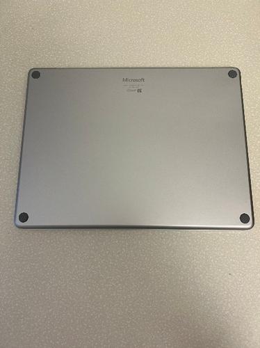
Place the device on an ESD safe soft surface with the bottom side facing up.
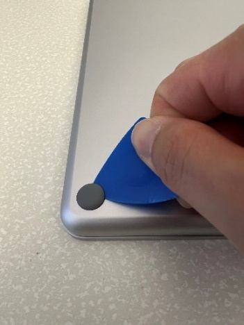
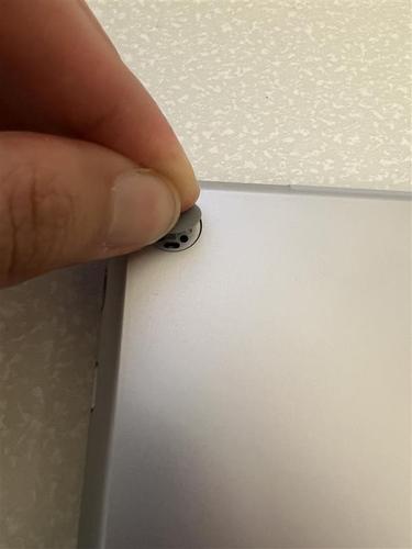
To pry up the foot, gently insert a plastic guitar pick between the foot, and the bottom D bucket. You might need to try gently inserting the pick from a different direction, but don't use a metal tool and only use the specified plastic tool.
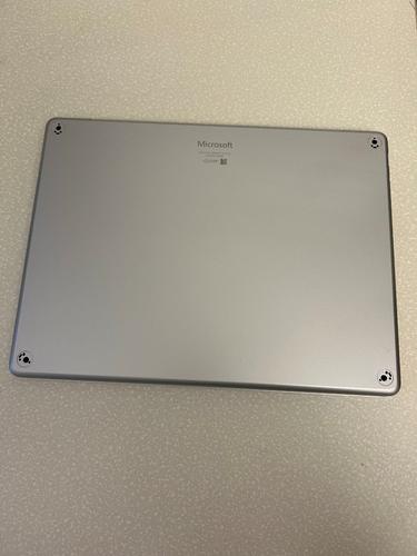
Repeat steps 1 and 2 to remove the remaining three feet and place them aside for reuse (if not damaged).
Procedure – Installation (feet)
Carefully align the grooves on the feet with the long hole on the D Bucket and press the foot down vertically until it's flat to the D Bucket.
Repeat the previous step for the remaining feet.
C Cover Replacement
Preliminary Requirements
Important
Be sure to follow all special (bolded) notes of caution within each process section.
Required Tools
- Soft ESD-Safe Mat or Benchtop
- Anti-static Wrist Strap (1 MOhm resistance)
- New Plastic Guitar Picks
- 5IP Torx Plus Screwdriver
- Sharpie
- Ruler
- Adjustable Torque Screwdriver that can be set to 1.2kgf-cm compatible with 5IP Torx Plus Bits or a preset 5IP Torx Plus Screwdriver (set to 1.2kgf-cm)
- Calipers with a resolution and accuracy of 0.01 mm
- Metal ESD Safe Tweezers
- Plastic ESD Safe Tweezers
- Plastic ESD Safe spudger
- 0.2mm Thick Feeler Gauge
- Isopropyl alcohol (70% IPA) and cleaning swabs
Primary Components
C Cover Keyset Subassembly
5 5IP Screws (for C Cover)
20 Trackpad Shims (four different thicknesses)
8 5IP Screws (for trackpad)
2 Conductive Tapes
4 Trackpad Alignment Papers
Procedure – Removal (C Cover)
Follow “Procedure – removal (feet)”
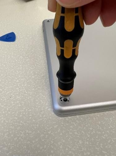
With the feet removed, use a 5IP Torx Plus screwdriver to remove the four newly exposed screws.
Important
To avoid any chance for screw stripping, be sure to press down firmly with the screwdriver. Additionally, keep track and count the number of screws removed to ensure there are no extra screws in the area.
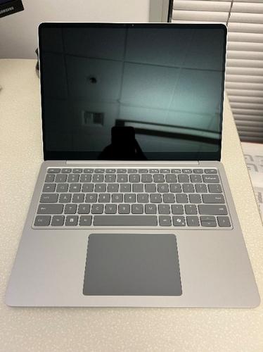
Gently flip the device around and open the display cover to the maximum angle.
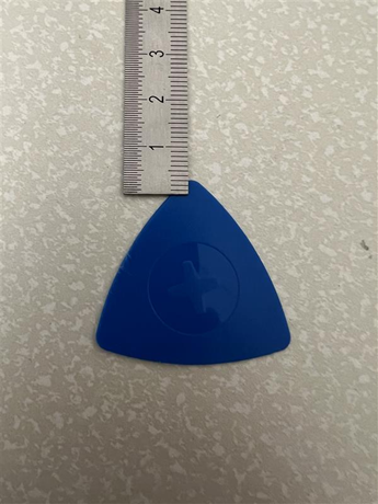
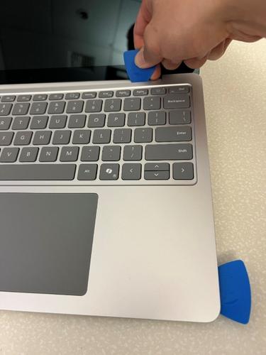
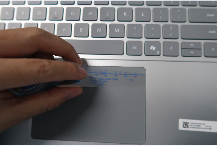
Use a sharpie and ruler to draw a line 3mm away from the edge of two guitar picks to prevent inserting the guitar pick too deep while removing the C Cover.
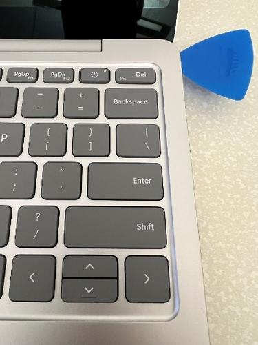
With your device flat on an ESD-safe surface for the remainder of this removal process, firmly but carefully insert the plastic guitar pick between the C Cover and the D bucket at least 5mm below the top right corner. Inserting the guitar pick requires some force and patience.
Important
Don't use a metal tool and only use the specified plastic tool.
Firmly but carefully, wiggle the guitar pick up and down until you hear a popping sound to disengage the nearby snap. With the snap disengaged, there's space between the C Cover and D bucket to gently slide the guitar pick along the right edge of the device.
Note
For the portion next to the keyboard, the pick might be inserted beyond 3mm to aid with removal. Below the keyboard, insertion must be limited to a maximum of 3mm.
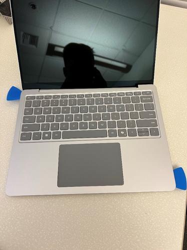
Repeat this process until all five snaps on the right edge are disengaged. Stop when you reach the bottom corner of the device.
Important
It's important to take your time during this step
Without inserting the guitar pick beyond the 3mm marked line, leave it in the bottom right corner to ensure the covers stay separated.
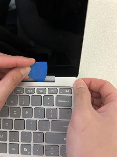
With one hand, gently lift and hold the top right corner of the C Cover. With your other hand, using another guitar pick, carefully disengage the snaps along the top edge of the C Cover, starting from the top right and moving to the top left. As you go along, once the nearby snap is disengaged, there's space between the C Cover and the D bucket - allowing you to gently slide the guitar pick along the top edge.
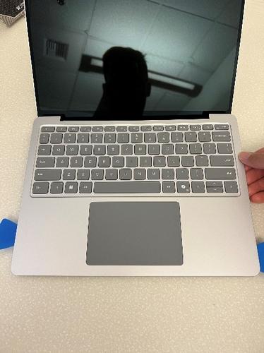
Firmly but carefully, insert the plastic guitar pick between the C Cover and the D bucket 5mm below the top left corner.
Firmly but carefully, wiggle the guitar pick up and down until you hear a popping sound to disengage the nearby snap. With the snap disengaged, there's space between the C Cover and D bucket to gently slide the guitar pick along the right edge of the device.
Note
For the portion next to the keyboard, the pick may be inserted beyond 3mm to aid with removal. Below the keyboard, insertion must be limited to a maximum of 3mm.
Repeat this process until all five snaps on the left edge are disengaged. Stop when you reach the bottom corner of the device.
Important
It's important to take your time during this step
With both hands, gently wiggle and tilt the bottom of the C Cover upwards towards the display cover and away from the battery to separate it from the D bucket.
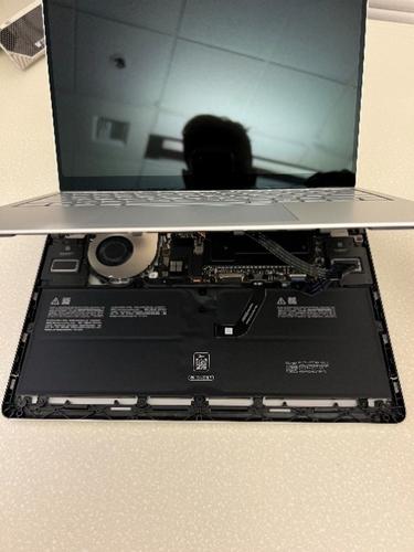
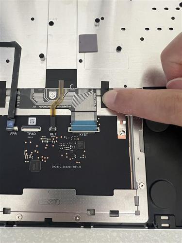
Use a plastic guitar pick to disengage the trackpad FPC buckle.
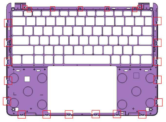
Disconnect the trackpad FPC and place the C Cover on an ESD safe, soft surface for reuse. Carefully inspect and count all 23 snaps and hooks on the C Cover and D bucket (seven at the top, five on the left, five on the right, and six on the bottom). If there are any missing or cracked snaps on the C Cover, it can't be reused. If there are any missing or cracked hooks on the D bucket, it can't be reused.
Procedure – Installation (C Cover)
Follow “Procedure – Removal (Trackpad)” without Steps 8 and 9.
Follow “Procedure – Installation (Trackpad)” without Step 10.
Use plastic tweezers to remove the liner on the top thermal pad.
Before continuing with the reassembly, inspect the device internals to ensure that no screws, foams, tape, or other foreign material is misplaced inside the unit.
Hold the C Cover with one hand and carefully install the FPC onto the motherboard receptacle. After the FPC is fully seated, use a plastic guitar pick to close the buckle on the receptacle.
Gently place the C Cover onto the D Bucket and slowly press down on the snaps around the entire perimeter of the C Cover.
Gently shake the device and listen carefully for any rattling sounds. If heard, follow “Procedure – Removal (C Cover)” Steps 3-15 and check for any loose connectors, screws, snaps, hooks, etc.
Turn the device over and use a 5IP Torx Plus Screwdriver to install the four screws. After the screws are snug and seated, only tighten the screws an additional ~1/8 turn (~45 degrees) to avoid stripping the threads.
Important
To avoid any chance for screw stripping, be sure to press down firmly with the screwdriver. Additionally, keep track and count the number of screws removed to ensure there are no extra screws in the area.
Follow “Procedure – Installation (Feet)”
Trackpad Replacement
Preliminary Requirements
Important
Be sure to follow all special (bolded) notes of caution within each process section.
Required Tools
- Soft ESD-Safe Mat or Benchtop
- Anti-static Wrist Strap (1 MOhm resistance)
- New Plastic Guitar Picks
- Adjustable Torque Screwdriver that can be set to 1.2kgf-cm compatible with 5IP Torx Plus Bits or a preset 5IP Torx Plus Screwdriver (set to 1.2kgf-cm)
- Calipers with a resolution and accuracy of 0.01mm
- Metal ESD Safe Tweezers
- Plastic ESD Safe Tweezers
- Plastic ESD Safe spudger
- 0.2mm Thick Feeler Gauge
- Isopropyl alcohol (70% IPA) and cleaning swabs
Primary Components
Trackpad Subassembly
5 5IP Screws (for C Cover)
20 Trackpad Shims (four different thicknesses)
8 5IP Screws (for trackpad)
2 Conductive Tapes
4 Trackpad Alignment Papers
1 Top Thermal Pad (for C Cover)
Procedure – Removal (Trackpad)
Download the latest SDT (surface diagnostic tool) version and follow the preinstallation touchpad repair (setup) workflow.
Follow “Procedure – Removal (Feet)”
Follow “Procedure – Removal (C Cover)
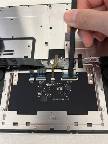
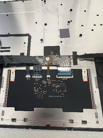
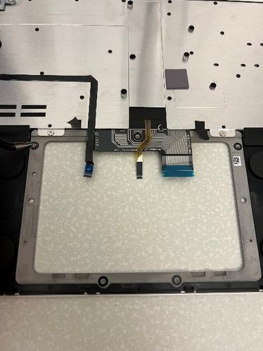
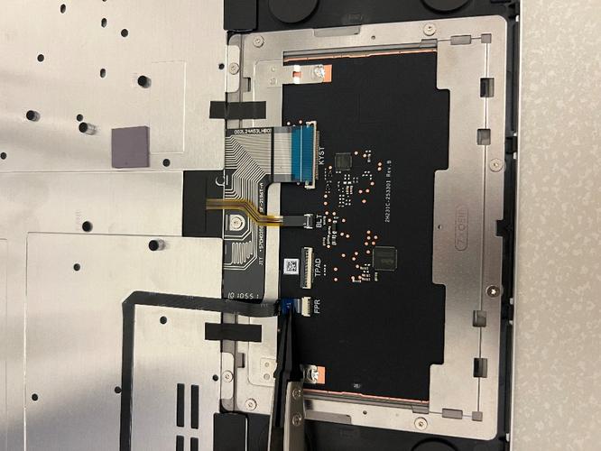
With a plastic prybar, disengage the four FPC buckles and remove the two grounding tapes on the trackpad.
Use isopropyl alcohol (70% IPA) and cleaning swabs to clean any adhesive remaining from the two grounding tapes.
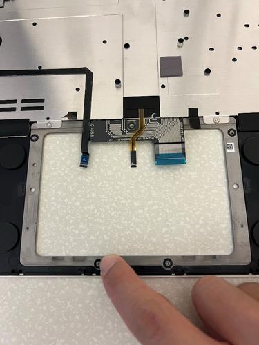
With your fingers, gently disconnect the four FPCs connected to the trackpad. Place the trackpad FPC gently aside on an ESD safe surface for reuse during reassembly if it isn't damaged.
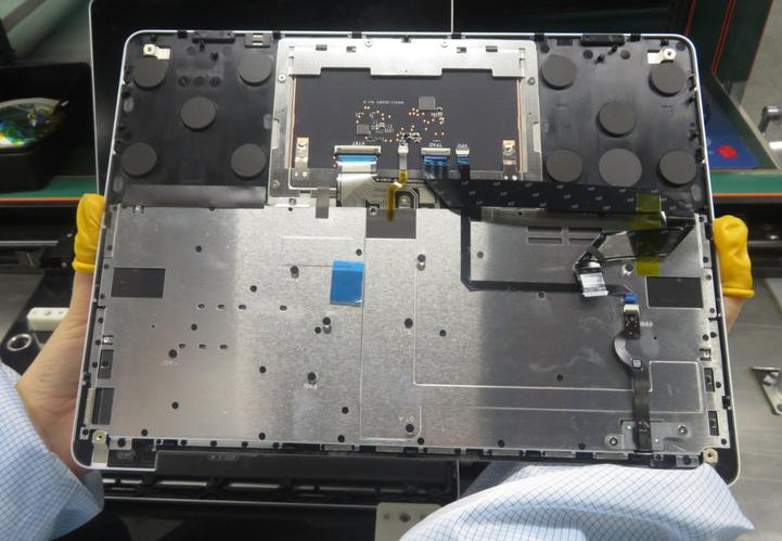
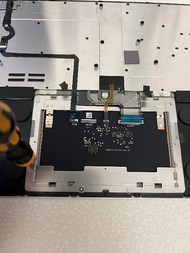
With a 5IP Torx Plus Screwdriver, remove the seven screws holding the Trackpad to the C Cover.

Important
To avoid any chance for screw stripping, be sure to press down firmly with the screwdriver. Additionally, count and keep track of the number of screws removed to ensure there are no extra screws in the area.
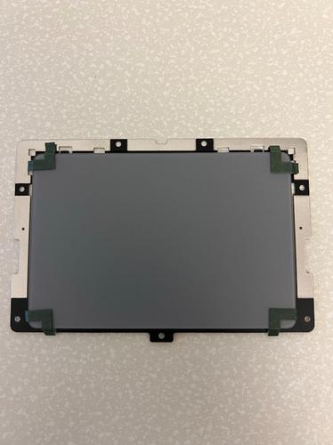
With your hand, remove the Trackpad subassembly from the C Cover.
With metal ESD safe tweezers, remove the black shims from the C Cover.
With plastic ESD safe tweezers, remove the thermal pad on the C Cover.
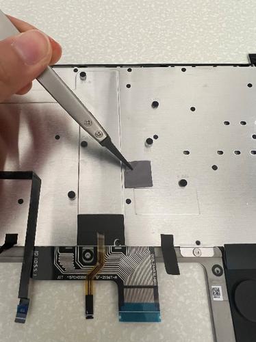
Use isopropyl alcohol (70% IPA) and cleaning swabs to clean any adhesive remaining from the black shims and the thermal pad.
Procedure – Installation (Trackpad)
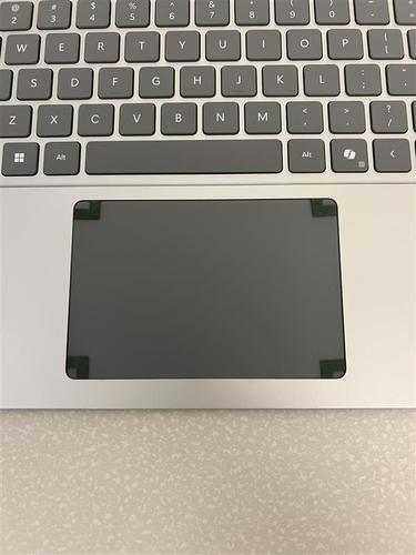
Attach alignment paper to the four corners of the Trackpad and press the corners down firmly. However, ensure the alignment paper doesn't fold between the trackpad and the bracket.
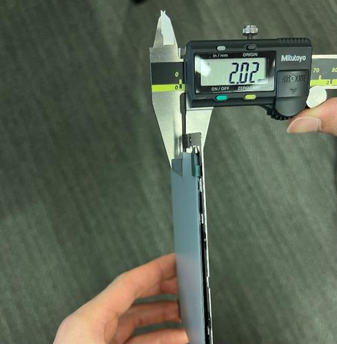
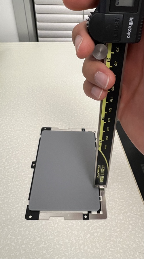
With calipers, measure the height between the top surface of the TP glass and the bottom surface of the TP bracket at each of the five shim locations. Then, measure the height between the top and bottom surface at each of the five shim locations. Using the difference between those two measurements at each shim location, determine which shim to install on to the C Cover by using the following guidance:
If the difference between the measurements is ≤ -0.05, don't install a shim at that location.
If the difference between the measurements is ≥ -0.05 and ≤ 0.05, install the 0.1-mm thick shim.
If the difference between the measurements is ≥ 0.05 and ≤ 0.1, install the 0.15-mm thick shim.
If the difference between the measurements is ≥ 0.1 and ≤ 0.15, install the 0.2-mm thick shim.
If the difference between the measurements is ≥ 0.15 and ≤ 0.30, install the 0.3-mm thick shim.
With your fingers, firmly press the shims in for 30 seconds each.
Gently insert the Trackpad subassembly into the C Cover and reassemble the seven 5IP screws with a 5IP Torx Plus Screwdriver set to 1.2kgf*cm.
Important
To avoid any chance for screw stripping, be sure to press down firmly with the screwdriver. Additionally, count and keep track of the number of screws removed to ensure there are no extra screws in the area.
With your fingers, carefully and gently remove the four alignment papers. Be sure that the entire alignment paper piece is removed and doesn't remain stuck between the C Cover and the Trackpad subassembly.
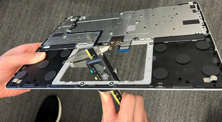
To ensure it's never above the C Cover surface at any point, gently flip around your C Cover and use a 0.2-mm feeler gauge around the entire perimeter of the Trackpad subassembly. Additionally, click the two bottom corners to check if the trackpad gets stuck against the C Cover surface. If it's, redo Step 7 from “Procedure – Removal (Trackpad) and Step 2 from “Procedure – Installation (Trackpad) before proceeding to the next step.
Gently flip around your C Cover and install two new grounding tapes. Be sure to firmly press them down for 30 seconds each.
With your fingers and plastic ESD safe tweezers, carefully reconnect the four FPCs to the trackpad.
With a plastic prybar, engage the four FPC buckles.
With your fingers, carefully place the new thermal pad aligned to the indents on the C Cover. Be sure to firmly press it down for 30 seconds.
Follow “Procedure – Installation (C Cover)”
Follow “Procedure – Installation (Feet)”
Download the latest SDT (surface diagnostic tool) version and follow the post-installation touchpad repair (validation) workflow.
SSD Replacement
Preliminary Requirements
Important
Be sure to follow all special (bolded) notes of caution within each process section.
Required Tools
- Soft ESD-Safe Mat or Benchtop
- Anti-static Wrist Strap (1 MOhm resistance)
- 5IP Torx Plus Screwdriver
- Plastic ESD Safe Tweezers
- Isopropyl alcohol (70% IPA) and cleaning swabs
- New Plastic Guitar Picks
Primary Components
- 1 SSD
- 5 5IP Screws (for C Cover)
- 1 Bottom Thermal Pad (for D Bucket)
- 2 5IP Screws (for SSD)
- 1 Top Thermal Pad (for C Cover)
- 1 Conductive Tape (for SSD)
Procedure – Removal (SSD)
Follow “Procedure – Removal (C Cover)”
With plastic ESD safe tweezers, remove the thermal pad on the C Cover.
Use isopropyl alcohol (70% IPA) and cleaning swabs to clean any adhesive remaining from the thermal pad.
With plastic ESD safe tweezers, remove the conductive tape on top of the SSD.
With a 5IP Torx Plus screwdriver, remove the 5IP screw holding down the SSD.
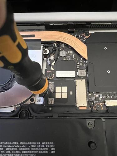
Important
To avoid any chance for screw stripping, be sure to press down firmly with the screwdriver. Additionally, count and keep track of the number of screws removed to ensure there are no extra screws in the area.
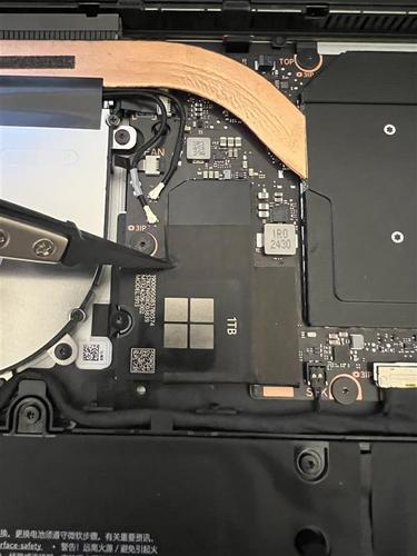
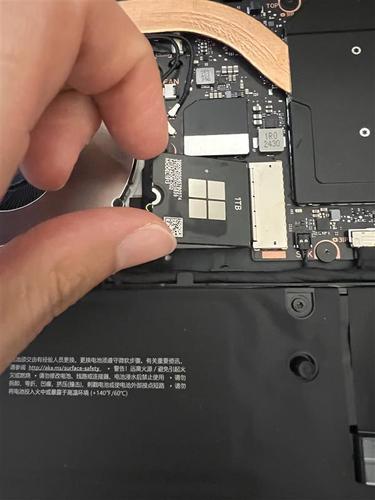
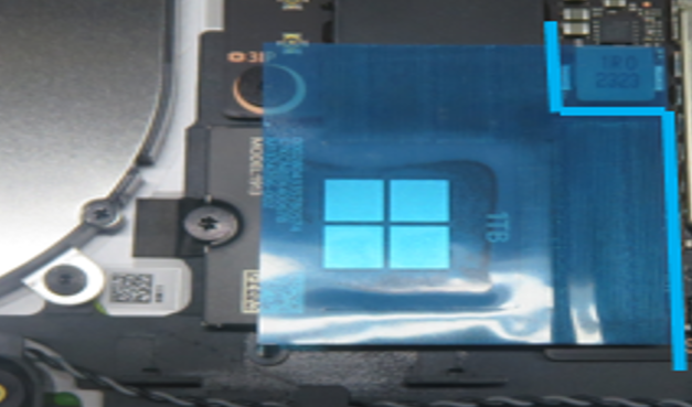
With your fingers, gently wiggle and lift the SSD out of the PCBA connector at a 15-degree angle.
With plastic ESD safe tweezers, remove the thermal pad on the D Bucket.
Use isopropyl alcohol (70% IPA) and cleaning swabs to clean any adhesive remaining from the thermal pad and on the SSD connector on the PCBA.
Procedure – Installation (SSD)
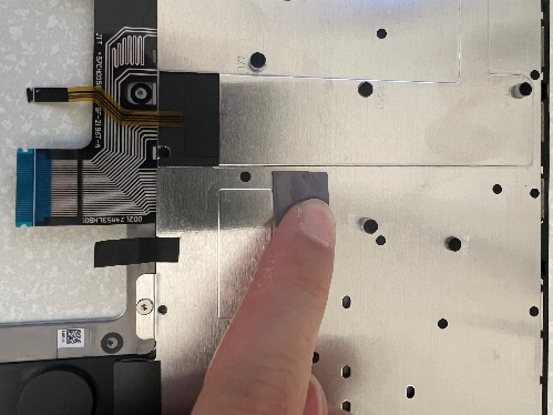
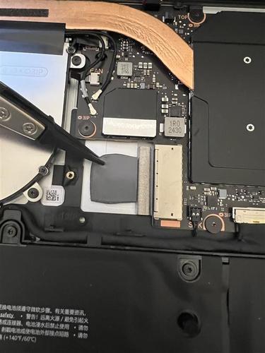
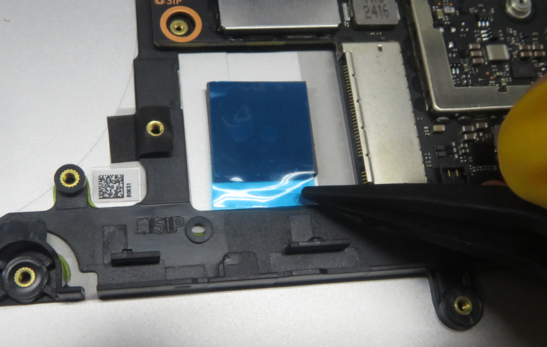
Use plastic tweezers to remove the liner on the bottom thermal pad, as shown in the following picture, and gently place it on the D Bucket. Be sure to lightly press it down for 30 seconds.
Gently install the SSD into the receptacle on the PCBA at a 15-degree angle.
Important
Ensure the foam isn't pinched between the receptacle and the pins on the SSD.
Use a 5IP Torx Plus screwdriver to tighten the one screw. After the screw is snug and seated, only tighten the screws an additional ~1/8 turn (~45 degrees) to avoid stripping the threads. Be sure to press down firmly with the screwdriver to avoid any chance for screw stripping. Additionally, count and keep track of the number of screws removed to ensure there are no extra screws in the area.
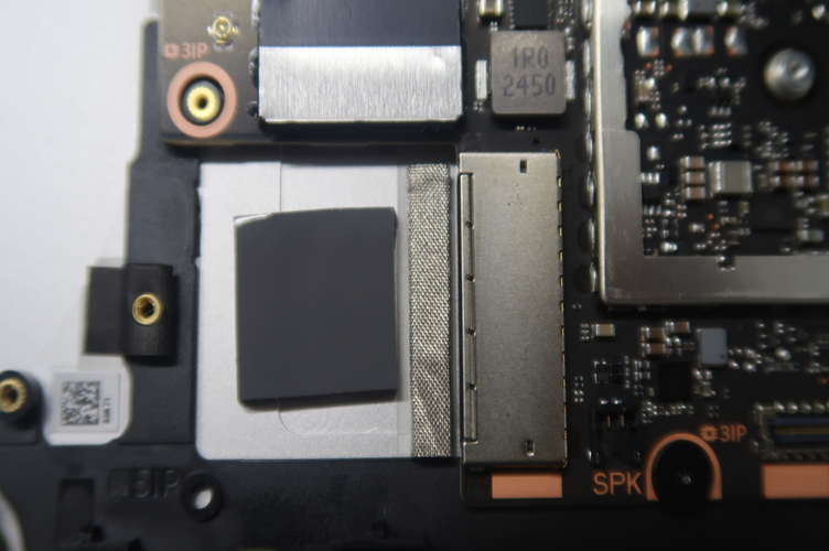
Use plastic tweezers to gently install the tape on top of the SSD and receptacles on the PCBA.
Remove the liner and use a plastic spudger to ensure the edges of the tape matches the arrangement in the following picture. Be sure to firmly press it down for 30 seconds.
Use plastic tweezers to remove the liner on the top thermal pad and gently place it on the C Cover, as shown in the following picture. Be sure to lightly press it down for 30 seconds.
Follow “Procedure – Installation (C Cover)”
Follow “Procedure – Installation (Feet)”
Battery Replacement
Preliminary Requirements
Important
Be sure to follow all special (bolded) notes of caution within each process section.
Required Tools
- Soft ESD-Safe Mat or Benchtop
- Anti-static Wrist Strap (1 MOhm resistance)
- 5IP Torx Plus Screwdriver
- Plastic ESD Safe Tweezers
- Isopropyl alcohol (70% IPA) and cleaning swabs
- Plastic ESD Safe Spudger
- 3IP Torx Plus Screwdriver
- New Plastic Guitar Picks
Primary Components
Battery Subassembly
10 5IP Screws (for Battery)
3 3IP Screws (for Battery)
5 5IP Screws (for C Cover)
1 Bottom Thermal Pad (for D Bucket)
2 5IP Screws (for SSD)
1 Top Thermal Pad (for C Cover)
1 Tape (for SSD)
Procedure – Removal (Battery)
Warning
Pre-Installtion Device Inspection: We recommend that, before handling the battery, the operator remove any personal jewelry, wear gloves and safety glasses, and have a bucket of sand prepared in the case of any battery event.
Warning
In the case of battery event, submerge entire device in sand. Don't attempt to pick up device. For more information, see Battery safety.
Download the latest SDT (surface diagnostic tool) version and follow the preinstallation battery repair (setup) workflow.
Follow “Procedure – Removal (SSD)”
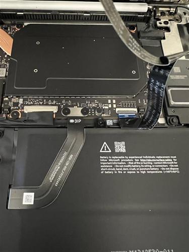
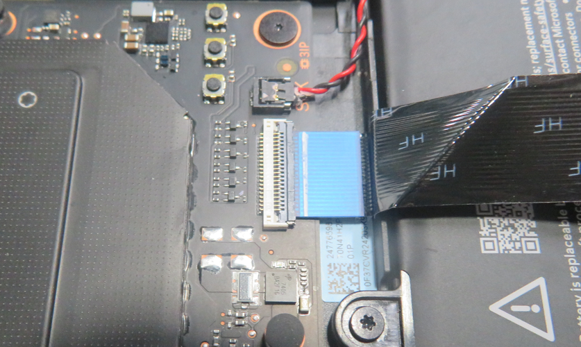
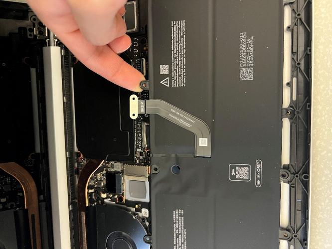
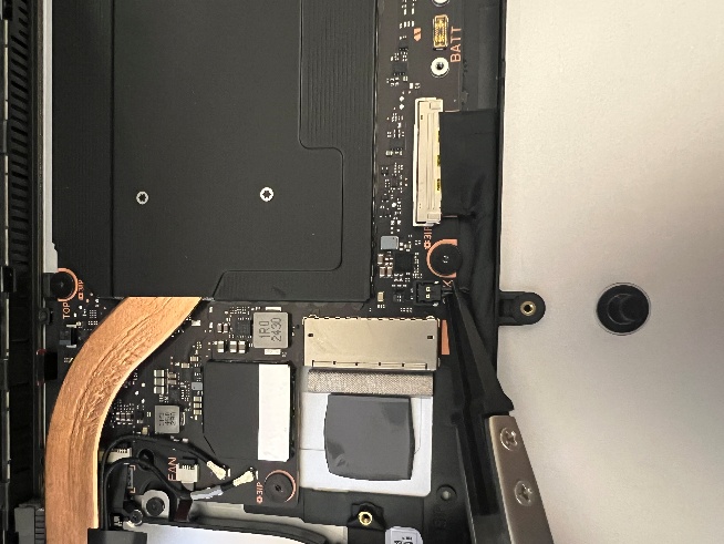
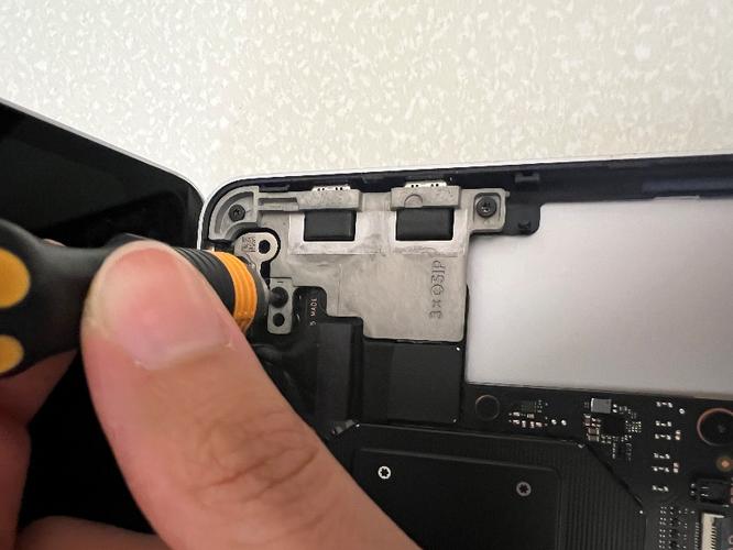
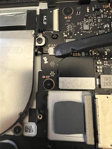
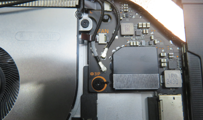
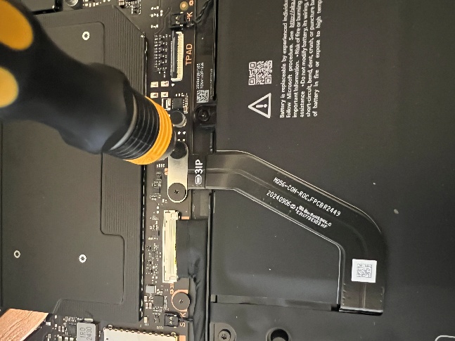
Use a 3IP Torx Plus Screwdriver to remove the two screws holding down the battery connector. Be careful as you're near the battery.
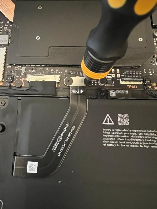
Important
To avoid any chance for screw stripping, be sure to press down firmly with the screwdriver. Additionally, count and keep track of the number of screws removed to ensure there are no extra screws in the area.
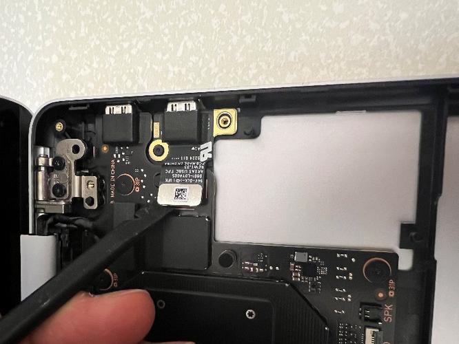
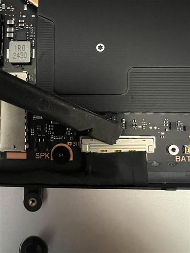
With a Plastic ESD Safe Prybar, gently disconnect the battery connector from the PCBA.
With a 5IP Torx Plus Screwdriver, remove the nine screws around the perimeter of the battery. Be careful as you're near the battery.
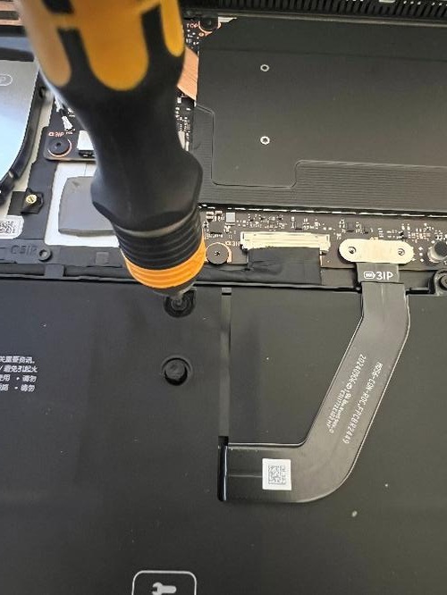
Important
To avoid any chance for screw stripping, be sure to press down firmly with the screwdriver. Additionally, count and keep track of the number of screws removed to ensure there are no extra screws in the area.
To prevent the device from potentially tipping over, tilt the display cover so that it's less than 75 degrees open.
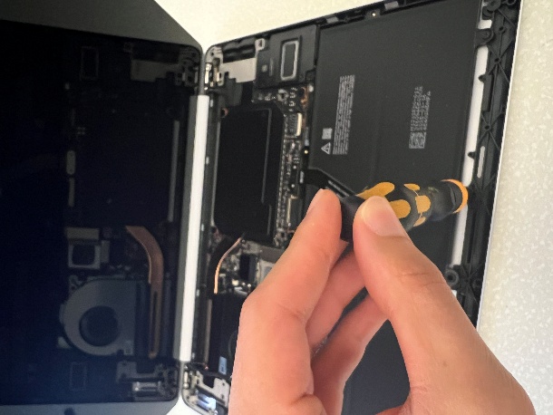
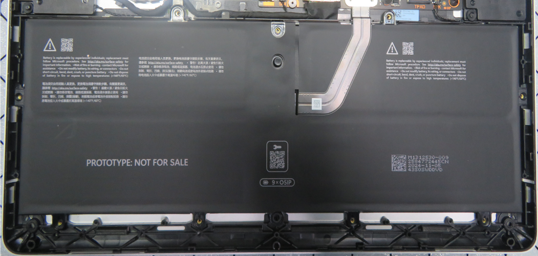
With your hands only touching the frame of the battery and not the cell itself, gently and carefully lift the battery frame away from the D Bucket.
Warning
Only handle the battery by the plastic frame. Bending, twisting, or impacting the battery might damage the battery, damage the device, and/or result in severe personal injury or property damage. Always use two hands when handling the battery.
Important
Place the battery in a location where it can't be accidentally contacted or damaged. When replacing the battery, dispose of the old battery according to local laws.
Procedure – Installation (Battery)
Preinstallation Device Inspection: Ensure that all screws are accounted for and there are no floating screws near the D Bucket where the battery will be installed. Also inspect the D-bucket for any loose articles for foreign debris that might be present.
Warning
Verify the battery's condition. Devices exhibiting battery issues as outlined in the Battery Inspection Process require replacement.
Gently use both hands to pick up the battery by the left and right lifting tabs only.
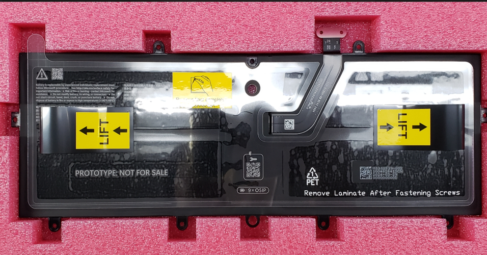
Warning
Only handle the new battery with the plastic tabs that come attached to the new battery. Bending, twisting, or impacting battery might damage the battery, damage the device, and/or result in severe personal injury or property damage. Always use two hands when handling the battery
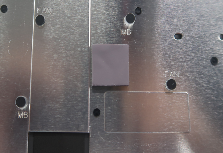
Gently use both hands to lower the battery into the D Bucket and ensure the positioning pin aligns to the hole on the battery.
Use a 5IP Torx Plus screwdriver to tighten the nine screws. After the screw is snug and seated, only tighten the screws an additional ~1/8 turn (~45 degrees) to avoid stripping the threads.
Important
To avoid any chance for screw stripping, be sure to press down firmly with the screwdriver. Additionally, count and keep track of the number of screws removed to ensure there are no extra screws in the area.
Caution
Don't overtighten screws on battery or battery frame. If the frame is cracked, the battery must not be used.
Important
Verify the battery's condition. Devices exhibiting battery issues as outlined in the Battery Inspection Process require replacement. If the battery was dropped, or if anything was dropped on the battery in the course of this repair, the battery should be replaced.
Use a 3IP Torx Plus screwdriver to tighten the two screws. After the screw is snug and seated, only tighten the screws an additional ~1/8 turn (~45 degrees) to avoid stripping the threads. Be sure to press down firmly with the screwdriver to avoid any chance for screw stripping. Additionally, count and keep track of the number of screws removed to ensure there are no extra screws in the area.
Follow “Procedure – Installation (SSD)”
Follow “Procedure – Installation (C Cover)”
Follow “Procedure – Installation (Feet)”
Download the latest SDT (surface diagnostic tool) version and follow the post-installation battery repair (validation) workflow.
Speaker Replacement
Preliminary Requirements
Important
Be sure to follow all special (bolded) notes of caution within each process section.
Required Tools
- Soft ESD-Safe Mat or Benchtop
- Anti-static Wrist Strap (1 MOhm resistance)
- 5IP Torx Plus Screwdriver
- Plastic ESD Safe Tweezers
- Isopropyl alcohol (70% IPA) and cleaning swabs
- Plastic ESD Safe Spudger
- New Plastic Guitar Picks
Primary Components
2 Speakers (right and left)
5 5IP Screws (for C Cover)
1 Bottom Thermal Pad (for D Bucket)
2 5IP Screws (for SSD)
1 Top Thermal Pad (for C Cover)
1 Tape (for SSD)
Procedure – Removal (Speaker)
Follow “Procedure – Removal (SSD)”
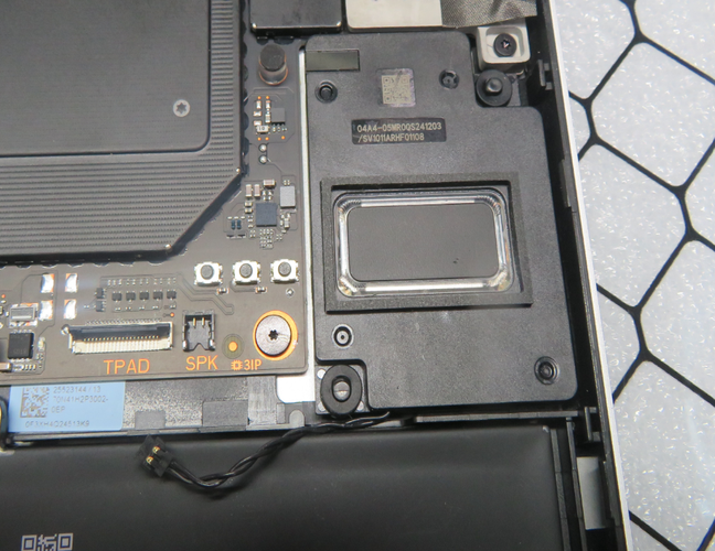
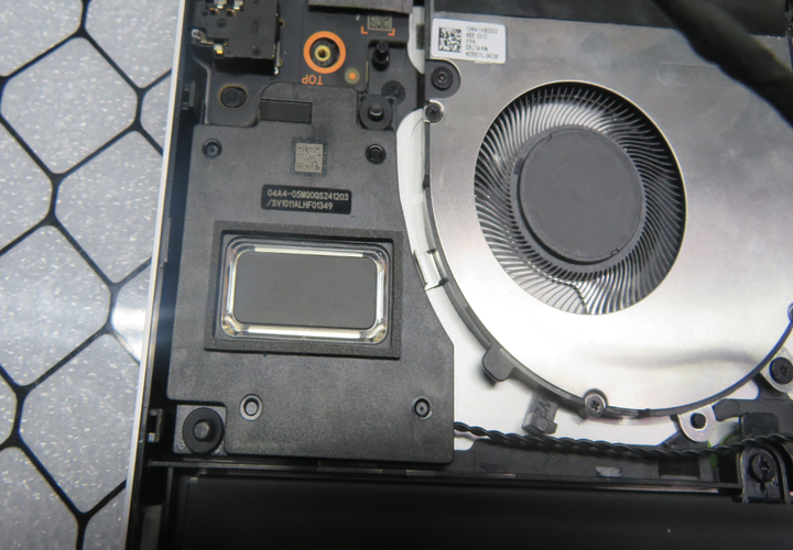
With your fingers and plastic ESD safe tweezers, gently disconnect the right speaker connector from the PCBA and remove the right speaker.
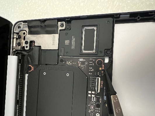
With your fingers and plastic ESD safe tweezers, gently disconnect the left speaker connector from the PCBA.
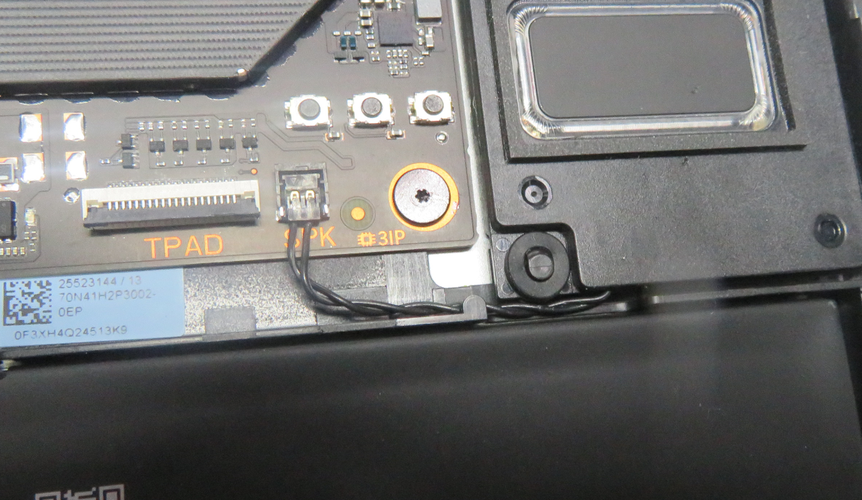
With your fingers and plastic ESD safe tweezers, gently route the left speaker connector out of the cable groove and away from the cable on top of it to eventually remove the left speaker.
Procedure – Installation (Speaker)
Gently install the right speaker onto the D Bucket and ensure the positioning pins are aligned with the holes on the speaker.
Gently route the right speaker connector through the ridge on the D Bucket to the receptacle on the motherboard and use a plastic spudger to ensure that it's fully seated.
Gently install the left speaker onto the D Bucket and ensure the positioning pins are aligned with the holes on the speaker.
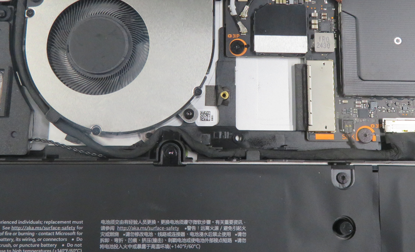
Gently unrouted the left display cable from the ridges on the D Bucket and gently route the left speaker connector through the ridges on the D Bucket to the receptacle on the motherboard and use a plastic spudger to ensure that it's fully seated.
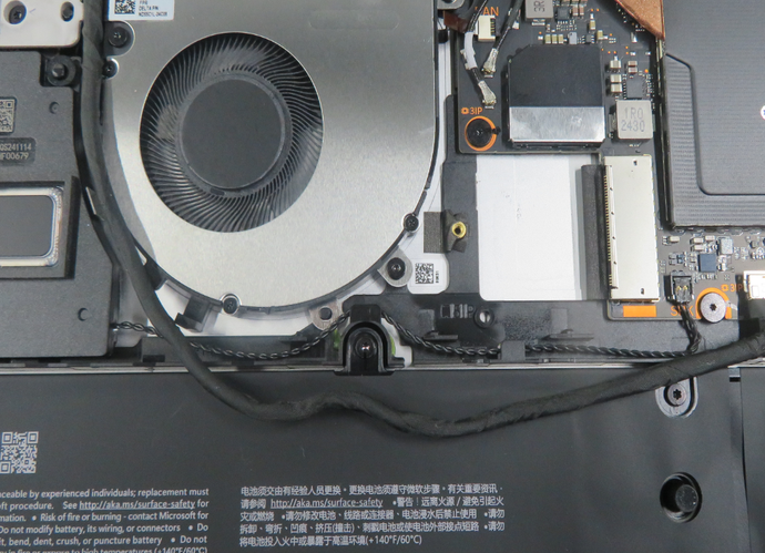
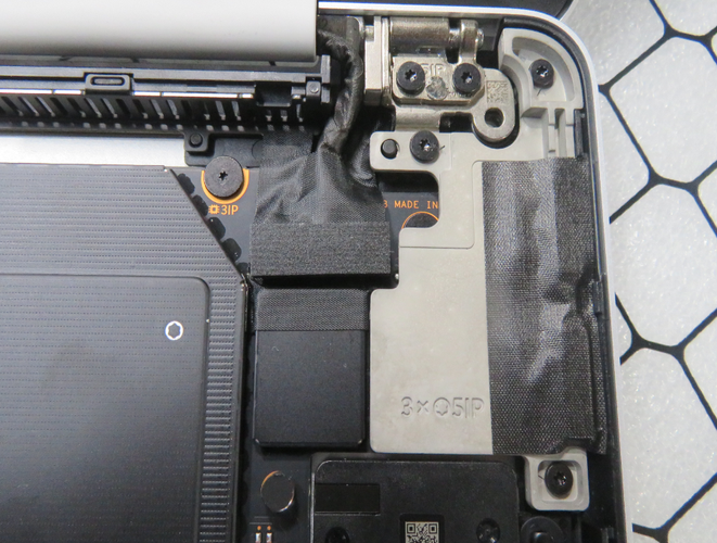
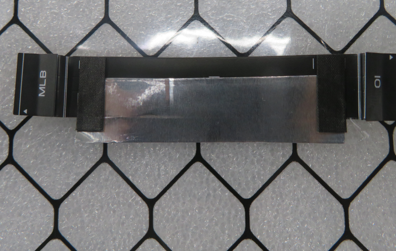
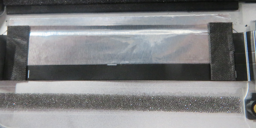
Gently reroute the left display cable through the ridges on the D Bucket and be sure that it's routed properly, as shown in the following picture.
Follow “Procedure – Installation (SSD)”
Follow “Procedure – Installation (C Cover)”
Follow “Procedure – Installation (Feet)”
USB-C Replacement
Preliminary Requirements
Important
Be sure to follow all special (bolded) notes of caution within each process section.
Required Tools
- Soft ESD-Safe Mat or Benchtop
- Anti-static Wrist Strap (1 MOhm resistance)
- 5IP Torx Plus Screwdriver
- Plastic ESD Safe Tweezers
- Isopropyl alcohol (70% IPA) and cleaning swabs
- Plastic ESD Safe Spudger
- 3IP Torx Plus Screwdriver
- New Plastic Guitar Picks
Primary Components
USB-C Subassembly
2 3IP Screws (for USB-C Daughterboard)
3 5IP Screws (for USB-C Bracket)
2 5IP Screws (for USB-C Bracket to Hinge)
1 USB-C Tape
5 5IP Screws (for C Cover)
1 Bottom Thermal Pad (for D Bucket)
2 5IP Screws (for SSD)
1 Top Thermal Pad (for C Cover)
1 Tape (for SSD)
Procedure – Removal (USB-C)
Follow “Procedure – Removal (SSD)”
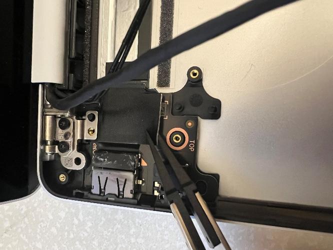
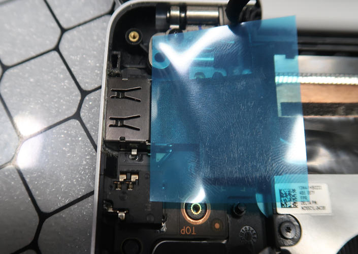
With plastic ESD safe tweezers, carefully remove the conductive tape on top of the USB-C connectors.
Use isopropyl alcohol (70% IPA) and cleaning swabs to clean any adhesive remaining on the bracket.
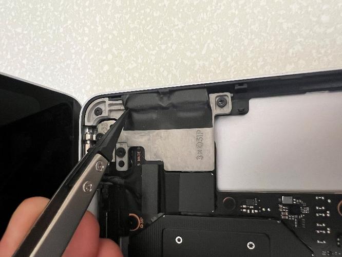
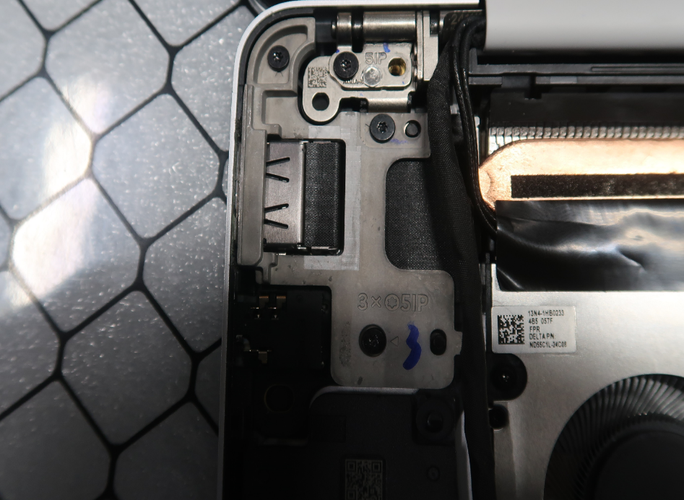
With a 5IP Torx Plus Screwdriver, remove the three 5IP screws holding down the USB-C bracket and remove the bracket. Be sure to press down firmly with the screwdriver to avoid any chance for screw stripping. Additionally, count and keep track of the number of screws removed to ensure there are no extra screws in the area.
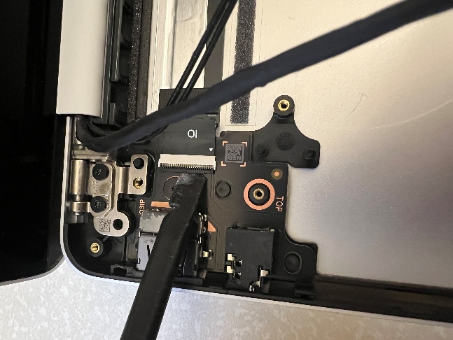
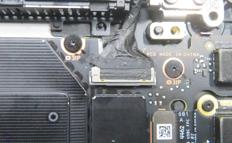
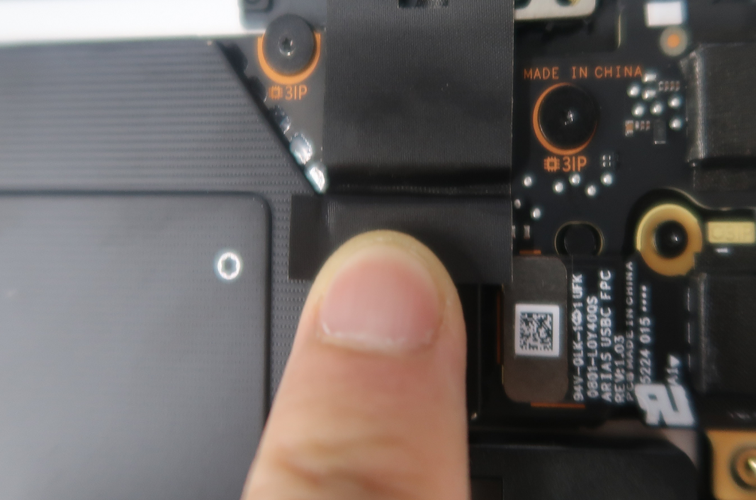
With a plastic ESD safe prybar, disconnect the USB-C FPC from the PCBA.
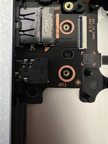
With a 3IP Torx Plus Screwdriver, remove the one 3IP screw and remove the USB-C daughterboard.
Important
To avoid any chance for screw stripping, be sure to press down firmly with the screwdriver. Additionally, count and keep track of the number of screws removed to ensure there are no extra screws in the area.
Procedure – Installation (USB-C)
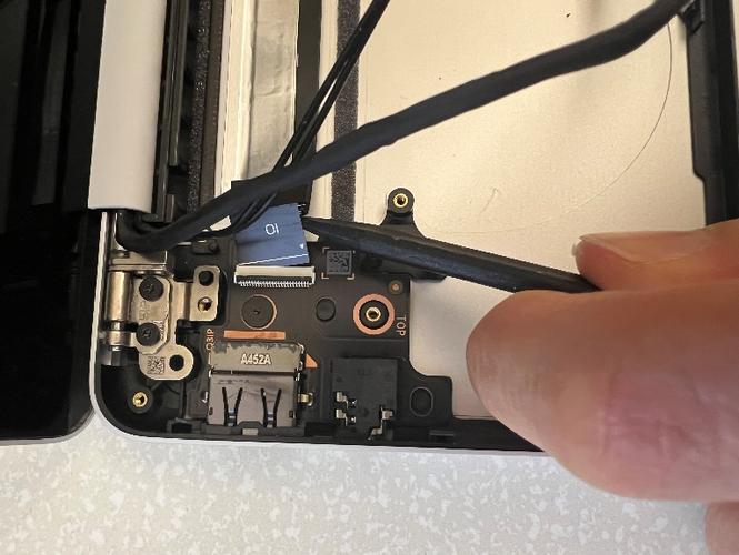
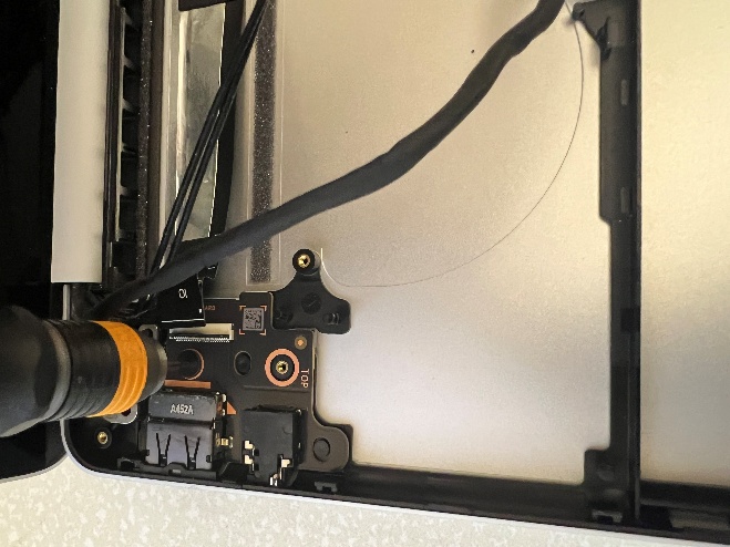
Gently install the USB-C daughterboard into the side hole of the D Bucket and align the screw holes.
Use a plastic spudger to connect the USB-C FPC to the connector on the PCBA. Ensure the FPC is flat and the USB-C subassembly isn't tilted upwards.
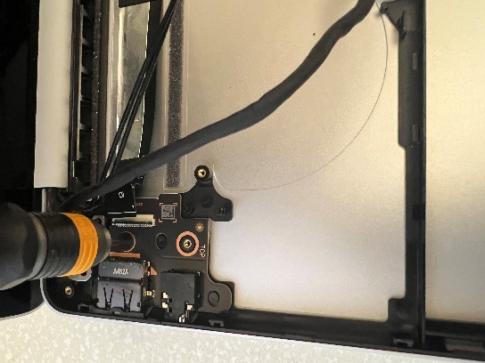
Use a 3IP Torx Plus screwdriver to tighten the one screw. After the screw is snug and seated, only tighten the screws an additional ~1/8 turn (~45 degrees) to avoid stripping the threads. Be sure to press down firmly with the screwdriver to avoid any chance for screw stripping. Additionally, count and keep track of the number of screws removed to ensure there are no extra screws in the area.
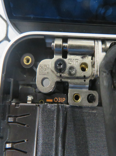
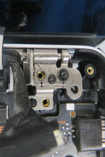
Assemble the reusable USB-C bracket and ensure the holes on the bracket are aligned to the screw holes on the hinge and D Bucket. Be sure to route any cables away.
Use a 5IP Torx Plus screwdriver to tighten the three screws. After the screw is snug and seated, only tighten the screws an additional ~1/8 turn (~45 degrees) to avoid stripping the threads. Be sure to press down firmly with the screwdriver to avoid any chance for screw stripping. Additionally, count and keep track of the number of screws removed to ensure there are no extra screws in the area.
Use plastic tweezers to line up and install the USB-C tape to the edge of the D Bucket. Be sure not to cover any screws.

Firmly press the tape down for 30 seconds.
Follow “Procedure – Installation (SSD)”
Follow “Procedure – Installation (C Cover)”
Follow “Procedure – Installation (Feet)”
Fan Replacement
Preliminary Requirements
Important
Be sure to follow all special (bolded) notes of caution within each process section.
Required Tools
- Soft ESD-Safe Mat or Benchtop
- Anti-static Wrist Strap (1 MOhm resistance)
- 5IP Torx Plus Screwdriver
- Plastic ESD Safe Tweezers
- Isopropyl alcohol (70% IPA) and cleaning swabs
- Plastic ESD Safe Spudger
- 3IP Torx Plus Screwdriver
- New Plastic Guitar Picks
Primary Components
Fan Subassembly
Fan/Thermal Module Tape
4 3IP Screws (for Fan)
5 5IP Screws (for C Cover)
1 Bottom Thermal Pad (for D Bucket)
2 5IP Screws (for SSD)
1 Top Thermal Pad (for C Cover)
1 Tape (for SSD)
Procedure – Removal (Fan)
Follow “Procedure – Removal (SSD)”
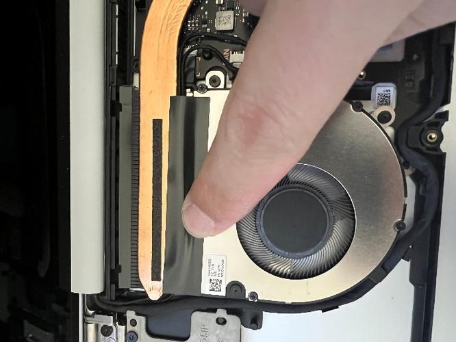
Using plastic ESD safe tweezers and your fingers, remove the tape on top of the fan.
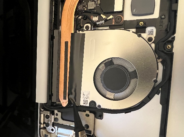
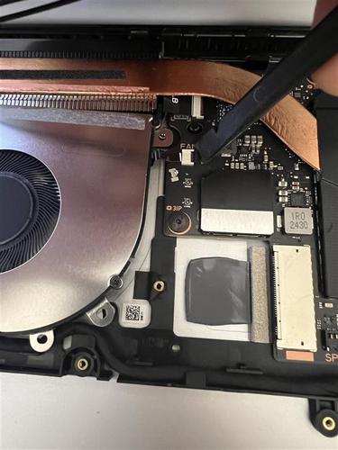
Using a plastic ESD safe prybar, disconnect the two antenna cables from the PCBA.
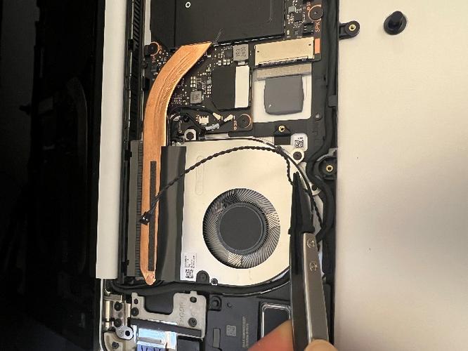
With a 3IP Torx Plus Screwdriver, remove the three 3IP screws holding the fan down to the D Bucket.

Important
To avoid any chance for screw stripping, be sure to press down firmly with the screwdriver. Additionally, count and keep track of the number of screws removed to ensure there are no extra screws in the area.
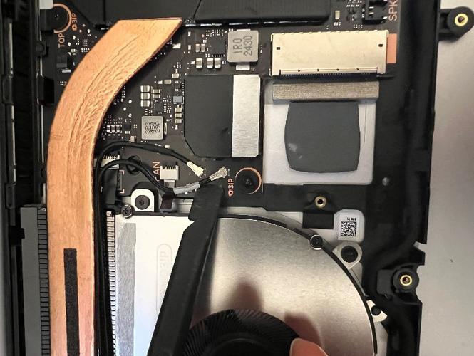
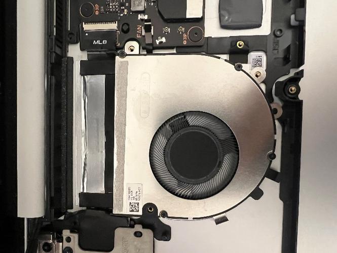
Using a plastic ESD safe prybar, disengage the buckle holding the fan FPC to the PCBA and disconnect the FPC.
With your hands, remove the fan and be mindful of the routed cable.
Use isopropyl alcohol (70% IPA) and cleaning swabs to clean any adhesive remaining from the tape on the thermal module.
Procedure – Installation (Fan)
Gently install the fan into the D Bucket and ensure the pins on the D Bucket align to the holes on the fan. Be sure to route any cables away.
Use a 3IP Torx Plus screwdriver to tighten the three screws. After the screw is snug and seated, only tighten the screws an additional ~1/8 turn (~45 degrees) to avoid stripping the threads. Be sure to press down firmly with the screwdriver to avoid any chance for screw stripping. Additionally, count and keep track of the number of screws removed to ensure there are no extra screws in the area.
Use plastic tweezers to connect the Fan FPC into the PCBA connector.
Use a plastic spudger to close the Fan FPC buckle on the PCBA connector.
Route the two antenna cables, but ensure the AB Cover Display cable is to the left of the two antenna cables and not on top them.
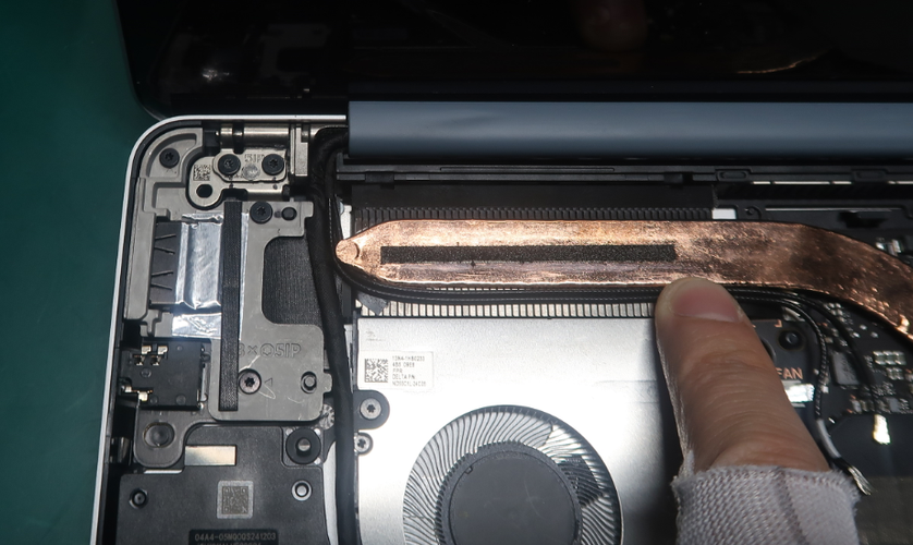
Reconnect the two antenna cables from the AB Cover display to the connectors on the PCBA. Be sure to use a plastic spudger and plastic tweezers to ensure they're fully seated in the ridges on the PCBA and connected to the receptacles on the PCBA.
Install the tape to secure the antenna cable routing and be sure to firmly press it down for 30 seconds.
Follow “Procedure – Installation (SSD)”
Follow “Procedure – Installation (C Cover)”
Follow “Procedure – Installation (Feet)”
Thermal Module Replacement
Preliminary Requirements
Important
Be sure to follow all special (bolded) notes of caution within each process section.
Required Tools
- Soft ESD-Safe Mat or Benchtop
- Anti-static Wrist Strap (1 MOhm resistance)
- 5IP Torx Plus Screwdriver
- Plastic ESD Safe Tweezers
- Isopropyl alcohol (70% IPA) and cleaning swabs
- Plastic ESD Safe Spudger
- 3IP Torx Plus Screwdriver
- New Plastic Guitar Picks
Primary Components
Thermal Module Subassembly
Thermal Module Shield
6 3IP Screws (for Thermal Module)
Fan/Thermal Module Tape
4 3IP Screws (for Fan)
5 5IP Screws (for C Cover)
1 Bottom Thermal Pad (for D Bucket)
2 5IP Screws (for SSD)
1 Top Thermal Pad (for C Cover)
1 Tape (for SSD)
Procedure – Removal (Thermal Module)
Follow “Procedure – Removal (Fan)”
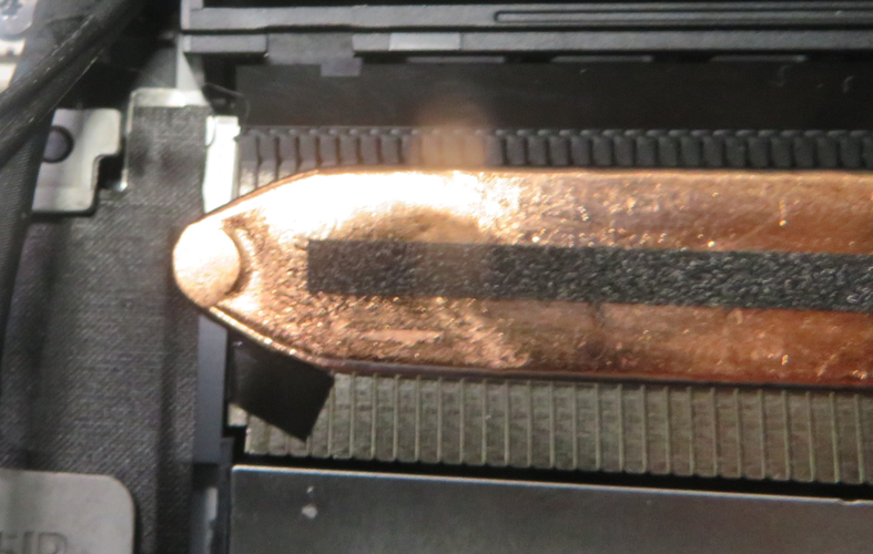
With a plastic ESD safe prybar, firmly pry up on the shield lid from the corner and around the entire perimeter to remove it.
With plastic ESD safe tweezers, slightly peel back the tape covering one of the thermal module screws.
Use a 3IP Torx Plus Screwdriver to remove the five screws in the labeled reverse order (4, 3, 2, 1).
Important
To avoid any chance for screw stripping, be sure to press down firmly with the screwdriver. Additionally, count and keep track of the number of screws removed to ensure there are no extra screws in the area.
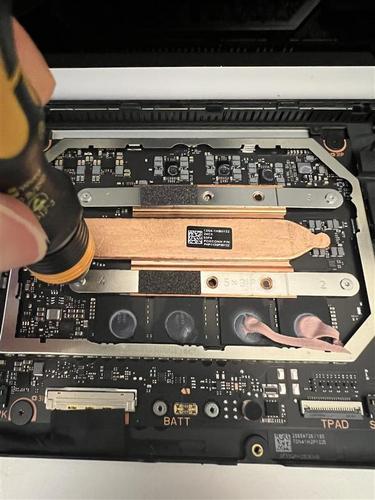
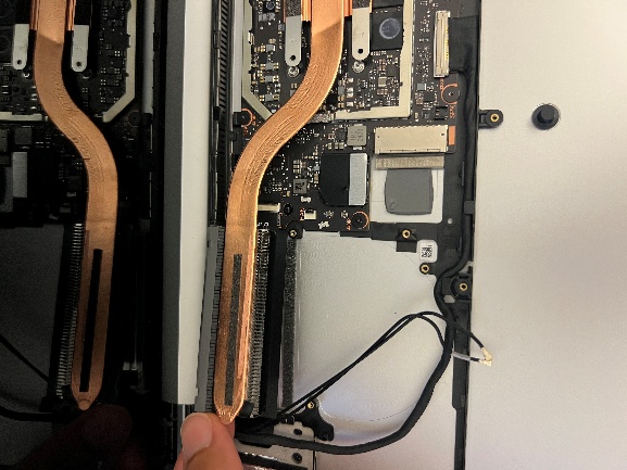
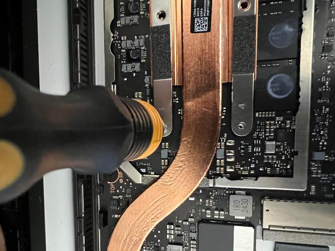
With your fingers, gently and slowly wiggle the left side of the thermal module away from the PCBA to remove it.
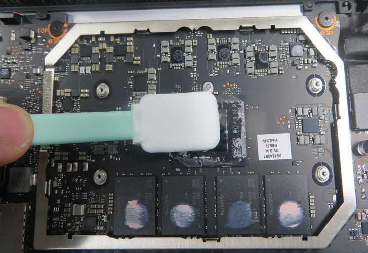
To clean any adhesive remaining on the PCBA, use a cotton swab with isopropyl alcohol (70% IPA).
Procedure – Installation (Thermal Module)
Gently install the thermal module onto the PCBA and ensure the holes on the thermal module line up with the pins on the D Bucket and PCBA. Be sure to route any cables, connectors, and tapes away.
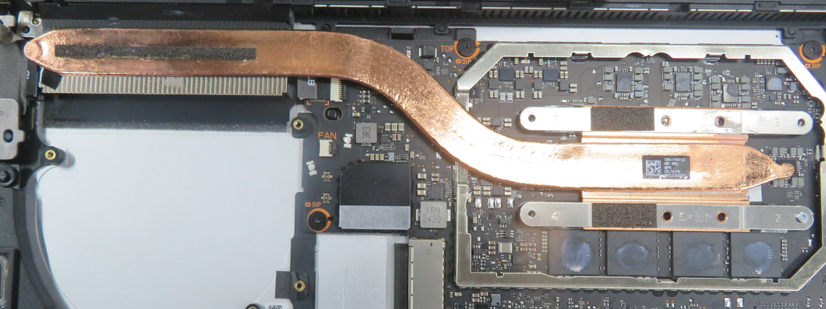
Use a 3IP Torx Plus screwdriver to install and lightly tighten the five new screws in the labeled correct order (1, 2, 3, 4). Be sure to press down firmly with the screwdriver to avoid any chance for screw stripping. Additionally, count and keep track of the number of screws removed to ensure there are no extra screws in the area.
Once all five screws are snug and seated, tighten them an additional ~1/8 turn (~45 degrees) to avoid stripping the threads.
Use a plastic spudger to ensure the tape on the USB-A and Audio Jack subassembly covers the top left Thermal Module screw.
Gently install the shield on top of the Thermal Module and use a plastic spudger to ensure the outer frame is assembled properly to the PCBA.
Follow “Procedure – Installation (Fan)”
Follow “Procedure – Installation (SSD)”
Follow “Procedure – Installation (C Cover)”
Follow “Procedure – Installation (Feet)”
USB-A and Audio Jack Replacement
Preliminary Requirements
Important
Be sure to follow all special (bolded) notes of caution within each process section.
Required Tools
- Soft ESD-Safe Mat or Benchtop
- Anti-static Wrist Strap (1 MOhm resistance)
- 5IP Torx Plus Screwdriver
- Plastic ESD Safe Tweezers
- Isopropyl alcohol (70% IPA) and cleaning swabs
- Plastic ESD Safe Spudger
- 3IP Torx Plus Screwdriver
- New Plastic Guitar Picks
Primary Components
USB-A and Audio Jack Subassembly
2 3IP Screws (for USB-A and Audio Jack Daughterboard)
3 5IP Screws (for USB-A and Audio Jack Bracket)
2 5IP Screws (for USB-A and Audio Jack Bracket to Hinge)
1 USB-A and Audio Jack Tape
1 USB-A and Audio Jack Foil
1 USB-A and Audio Jack Gasket
5 5IP Screws (for C Cover)
1 Bottom Thermal Pad (for D Bucket)
2 5IP Screws (for SSD)
1 Top Thermal Pad (for C Cover)
1 Tape (for SSD)
Procedure – Removal (USB-A and Audio Jack)
Follow “Procedure – Removal (SSD)”
With a 5IP Torx Plus Screwdriver, remove the three screws holding down the USB-A and Audio Jack bracket and remove it with your fingers. You must use sufficient force to overcome the adhesive holding it down.
Important
To avoid any chance for screw stripping, be sure to press down firmly with the screwdriver. Additionally, count and keep track of the number of screws removed to ensure there are no extra screws in the area.
With plastic ESD safe tweezers, remove the tape on top of the connector. If the AB Cover display and thermal module are still attached, be careful not to pinch any of the cables.
With a plastic ESD safe prybar, disengage the buckle holding down the USB-A and Audio Jack FPC.
With a plastic ESD safe prybar and plastic ESD-safe tweezers, disconnect the USB-A and Audio Jack FPC.
With a 3IP Torx Plus Screwdriver, remove the one 3IP screw holding down the USB-A and Audio Jack board.
Important
To avoid any chance for screw stripping, be sure to press down firmly with the screwdriver. Additionally, count and keep track of the number of screws removed to ensure there are no extra screws in the area.
With your fingers and a plastic ESD safe prybar, wiggle and lift up on the USB-A and Audio Jack board to remove it.
With a plastic ESD safe prybar, remove the foil and gasket on the USB-A and Audio Jack bracket.
Use isopropyl alcohol (70% IPA) and cleaning swabs to clean any adhesive remaining on the bracket.
Procedure – Installation (USB-A and Audio Jack)
Gently place the USB-A and Audio Jack daughterboard into the D Bucket and ensure the board is flat and the holes are fully aligned with the positioning pin.
Use a 3IP Torx Plus screwdriver to tighten the one screw. After the screw is snug and seated, only tighten the screws an additional ~1/8 turn (~45 degrees) to avoid stripping the threads. Be sure to press down firmly with the screwdriver to avoid any chance for screw stripping. Additionally, count and keep track of the number of screws removed to ensure there are no extra screws in the area.
Use plastic tweezers to line up and install the USB-A and Audio Jack absorber to the edge of the USB connector.
Use a plastic spudger to firmly press the absorber down for 30 seconds.
Assemble the reusable USB-A and Audio Jack bracket and ensure the holes on the bracket are aligned to the screw holes on the daughterboard. Be sure to route any cables away.
Use a 5IP Torx Plus screwdriver to tighten the three screws. After the screw is snug and seated, only tighten the screws an additional ~1/8 turn (~45 degrees) to avoid stripping the threads. Be sure to press down firmly with the screwdriver to avoid any chance for screw stripping. Additionally, count and keep track of the number of screws removed to ensure there are no extra screws in the area.
Use plastic tweezers to line up and install the USB-A and Audio Jack foil to the edge of the USB connector. Be sure not to cover any screws.
Use plastic tweezers to line up and install the USB-A and Audio Jack gasket to the edge of the bracket. Be sure not to cover any screws.
Follow “Procedure – Installation (SSD)”
Follow “Procedure – Installation (C Cover)”
Follow “Procedure – Installation (Feet)”
AB Cover (Display) Replacement
Preliminary Requirements
Important
Be sure to follow all special (bolded) notes of caution within each process section.
Required Tools
- Soft ESD-Safe Mat or Benchtop
- Anti-static Wrist Strap (1 MOhm resistance)
- 5IP Torx Plus Screwdriver
- Plastic ESD Safe Tweezers
- Isopropyl alcohol (70% IPA) and cleaning swabs
- Plastic ESD Safe Spudger
- 0.25mm Thick Feeler Gauge
- 0.3mm Thick Feeler Gauge
- 0.05mm Thick Feeler Gauge
- New Plastic Guitar Picks
Primary Components
1 AB Cover (Display) Subassembly
1 Top Display Connector Tape
1 Top Display Connector Foam
5 5IP Screws (for AB Cover Hinges)
3 5IP Screws (for USB-A and Audio Jack Bracket)
2 5IP Screws (for USB-A and Audio Jack Bracket to Hinge)
1 USB-A and Audio Jack Foil
1 USB-A and Audio Jack Gasket
2 5IP Screws (for USB-C Daughterboard)
3 5IP Screws (for USB-C Bracket)
1 USB-C Tape
1 Fan/Thermal Module Tape
5 5IP Screws (for C Cover)
1 Bottom Thermal Pad (for D Bucket)
2 5IP Screws (for SSD)
1 Top Thermal Pad (for C Cover)
1 Tape (for SSD)
Procedure – Removal (AB Cover)
Download the latest SDT (surface diagnostic tool) version and follow the pre-installation touch display repair (setup) workflow.
Follow “Procedure – Removal (SSD)”
With a 5IP Torx Plus Screwdriver, remove the three screws holding down the USB-A and Audio Jack bracket and remove it with your fingers. You must use sufficient force to overcome the adhesive holding it down.
Important
To avoid any chance for screw stripping, be sure to press down firmly with the screwdriver. Additionally, count and keep track of the number of screws removed to ensure there are no extra screws in the area.
With plastic ESD safe tweezers, carefully remove the conductive tape on top of the USB-C connectors.
Use isopropyl alcohol (70% IPA) and cleaning swabs to clean any adhesive remaining on the bracket.
With a 5IP Torx Plus Screwdriver, remove the three 5IP screws holding down the USB-C bracket and remove the bracket. Be sure to press down firmly with the screwdriver to avoid any chance for screw stripping. Additionally, count and keep track of the number of screws removed to ensure there are no extra screws in the area.
Using plastic ESD safe tweezers and your fingers, remove the tape on top of the fan.
Use isopropyl alcohol (70% IPA) and cleaning swabs to clean any adhesive remaining on the fan.
Using a plastic ESD safe prybar, disconnect the two antenna cables from the PCBA.
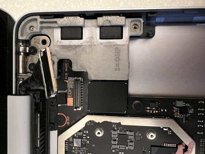
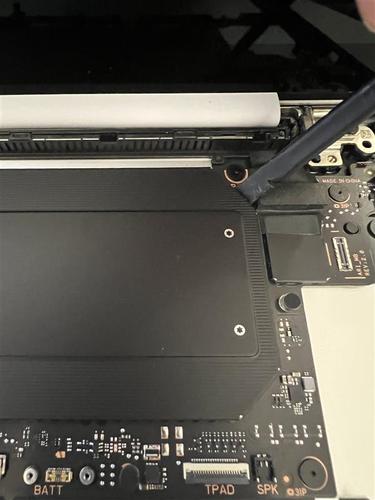
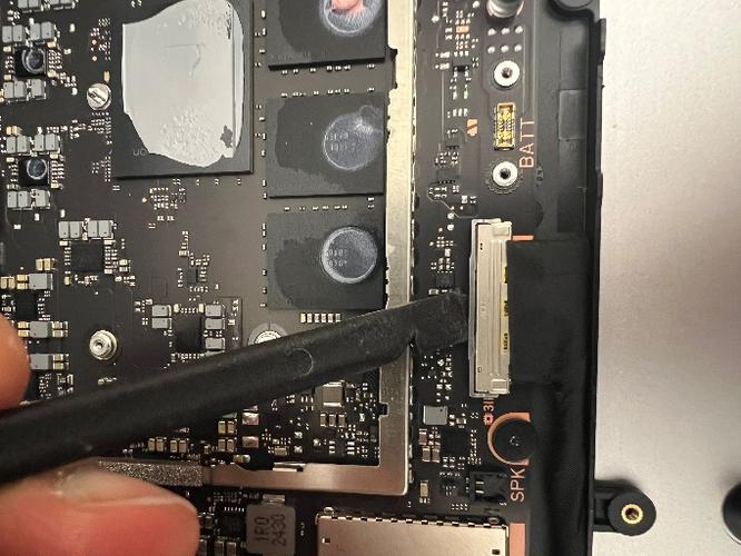
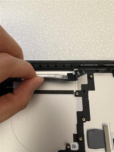
With a plastic ESD safe prybar, disengage the bottom display connector buckle on the PCBA and gently disconnect the cable with your fingers.
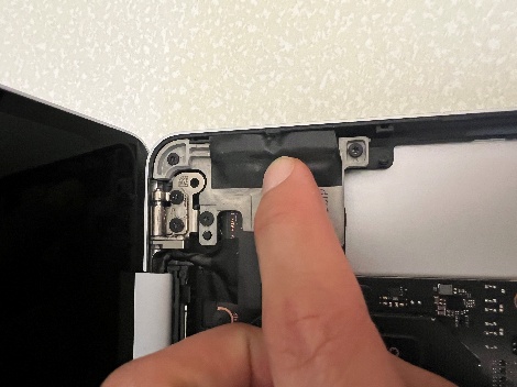
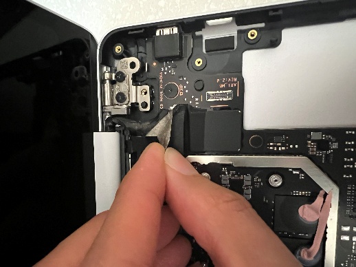
With a plastic ESD safe prybar, gently lift the top display cable upwards and use your fingers to remove the tape.
Use isopropyl alcohol (70% IPA) and cleaning swabs to clean any adhesive remaining from the removed tape.
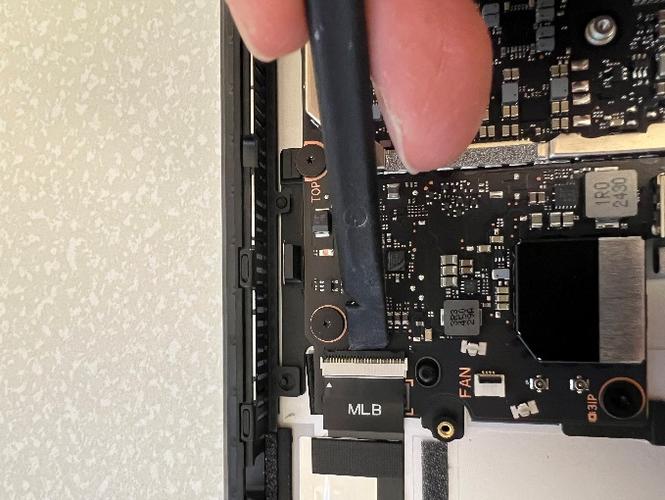
With a plastic ESD safe prybar, disengage the top display connector buckle on the PCBA and gently disconnect the cable with your fingers.
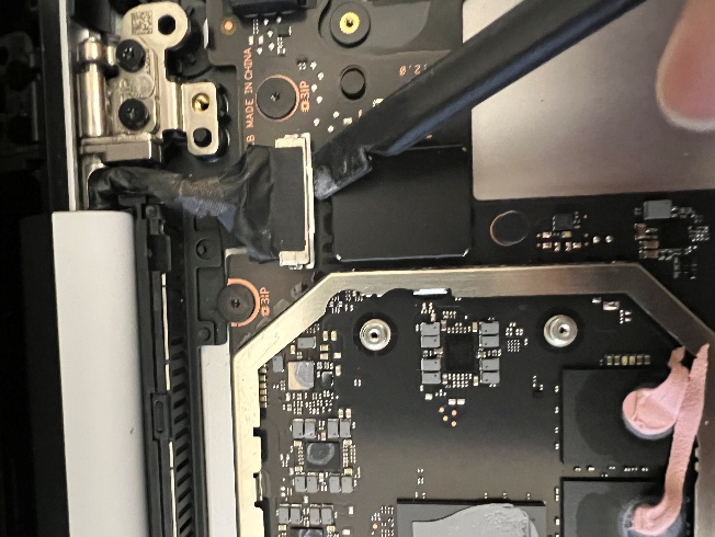
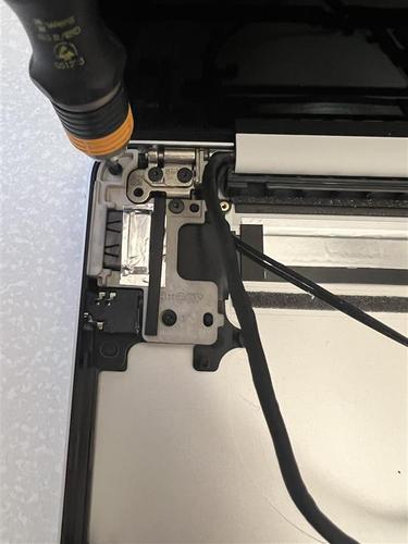
Adjust the display cover to about 90 degrees and use a 5IP Torx Plus Screwdriver to remove the four 5IP screws on the two hinges. Be sure to press down firmly with the screwdriver to avoid any chance for screw stripping. Additionally, count and keep track of the number of screws removed to ensure there are no extra screws in the area.
Using both hands, gently wiggle and remove the AB Cover display from the D Bucket.
Procedure – Installation (AB Cover)
Gently line up the AB Cover to the D Bucket and ensure the pins on the D Bucket are aligned to the holes on the hinges.
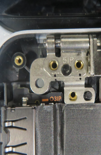
Use a 5IP Torx Plus Screwdriver to lightly install one screw per hinge. Be sure to hold the AB Cover display with one hand so the device doesn't fall over. Be sure to press down firmly with the screwdriver to avoid any chance for screw stripping. Additionally, count and keep track of the number of screws removed to ensure there are no extra screws in the area.
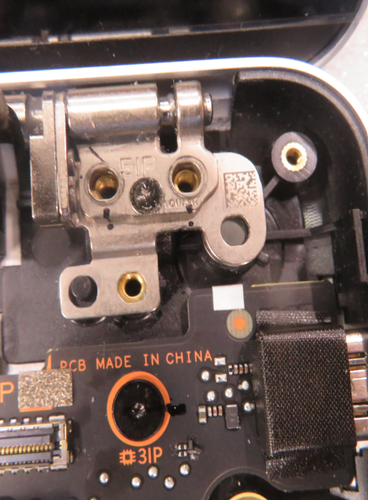
Close the AB Cover display but be careful not to clamp down on any wires. Adjust the positioning of the AB Cover display while the screws are still not fully seated to ensure the AB Cover display step to the D Bucket is within 0.25mm and 0.3mm on both sides (feeler gauge) and the AB Cover display gap to the D Bucket is within 0.05mm and 0.25mm on both sides before moving on to the next step.
Open the AB Cover display <90 degrees to ensure the device doesn't fall over. Use a 5IP Torx Plus screwdriver to install the remaining screw on each hinge. Tighten all four hinge screws until they're snug and seated and then only tighten the screws an additional ~1/4 turn (~90 degrees) to avoid stripping the threads. Be sure to press down firmly with the screwdriver to avoid any chance for screw stripping. Additionally, count and keep track of the number of screws removed to ensure there are no extra screws in the area.
Follow “Procedure – Installation (USB-A and Audio Jack)” Steps 1-8
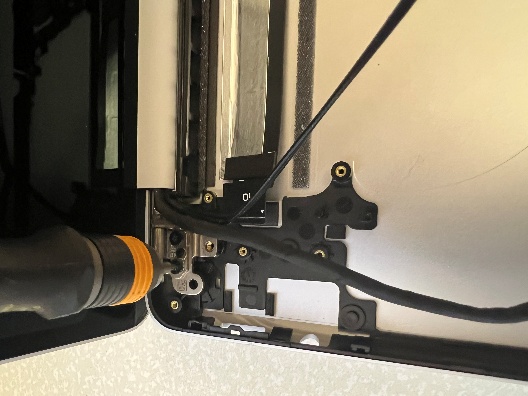
Route the two antenna cables but ensure the AB Cover Display cable is to the left of the two antenna cables and not on top them.
Reconnect the two antenna cables from the AB Cover display to the connectors on the PCBA. Be sure to use a plastic spudger to ensure they're fully seated and connected.
Install the tape to secure the antenna cable routing and be sure to firmly press it down for 30 seconds.
Gently install the top AB Cover Display cable to the connector on the PCBA and use a plastic spudger to ensure the buckle is closed.
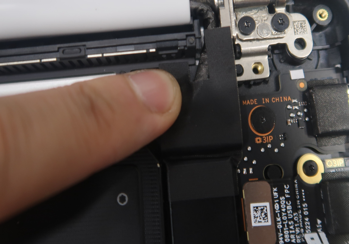
Use plastic tweezers to align the display connector tape to the edge of the thermal module shield and plastic hinge on the D Bucket.
Use a plastic spudger to firmly secure the display connector tape into the gap and crease.
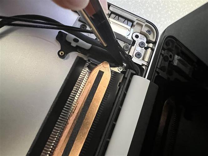
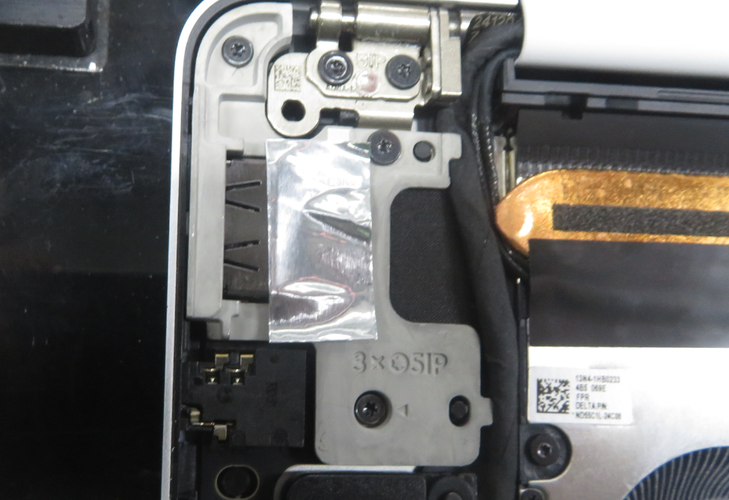
Firmly press the display connector tape down for 30 seconds at the location shown in the following picture.
Use a plastic spudger to firmly secure the display connector tape into the gap and crease with the thermal module shield.
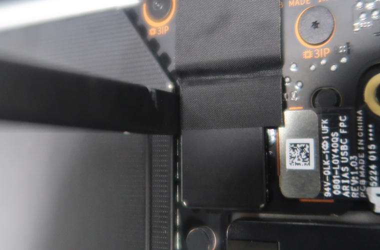
Use a plastic spudger to firmly secure the display connector tape into the gap and crease with the USB-C connector on the PCBA.
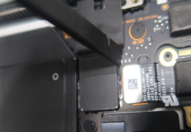
Firmly press the display connector tape down for 30 seconds at the location shown in the following picture.
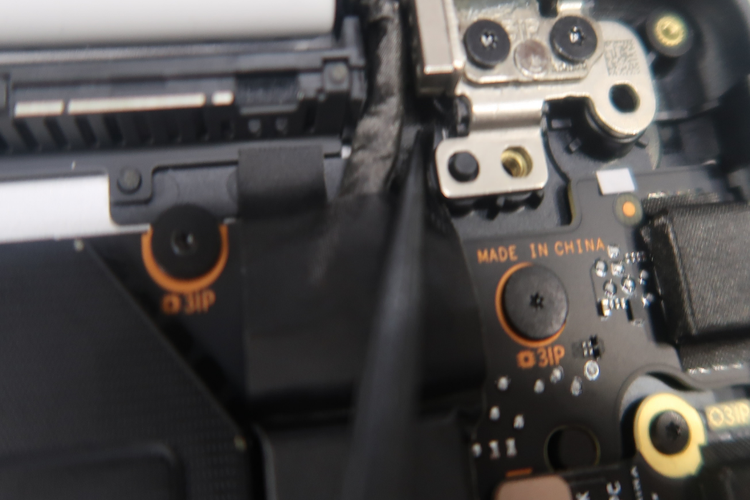
Use a plastic spudger to firmly secure the display connector tape into the gap and crease with the AB Cover Display hinge.
Follow “Procedure – Installation (USB-C)” Steps 4-7
Use plastic tweezers to install the display connector foam aligned with the USB-C bracket, as shown in the following picture.
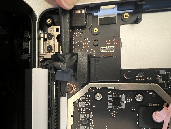
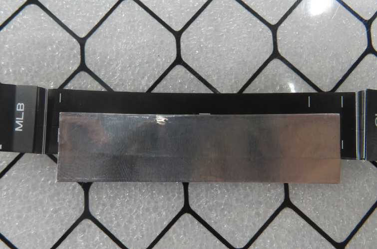
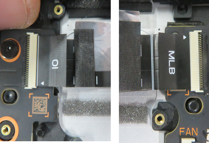
Gently route the left display cable through the ridges on the D Bucket and connect it with the bottom receptacle on the PCBA. Be sure that it's routed properly, as shown in the following picture.
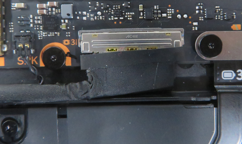
Use a plastic spudger to ensure the buckle on the display connector is closed.
Follow “Procedure – Installation (SSD)”
Follow “Procedure – Installation (C Cover)”
Follow “Procedure – Installation (Feet)”
Download the latest SDT (surface diagnostic tool) version and follow the post-installation touch display repair (validation) and touch display (calibration) workflows.
PCBA Replacement
Preliminary Requirements
Important
Be sure to follow all special (bolded) notes of caution within each process section.
Required Tools
- Soft ESD-Safe Mat or Benchtop
- Anti-static Wrist Strap (1 MOhm resistance)
- 5IP Torx Plus Screwdriver
- Plastic ESD Safe Tweezers
- Isopropyl alcohol (70% IPA) and cleaning swabs
- Plastic ESD Safe Spudger
- 3IP Torx Plus Screwdriver
- New Plastic Guitar Picks
Primary Components
1 PCBA Subassembly
8 3IP Screws (for PCBA)
3 3IP Screws (for Battery)
1 Top Display Connector Tape
1 Top Display Cable Tape
1 Top Display Connector Foam
5 5IP Screws (for AB Cover Hinges)
3 5IP Screws (for USB-A and Audio Jack Bracket)
2 5IP Screws (for USB-A and Audio Jack Bracket to Hinge)
1 USB-A and Audio Jack Foil
1 USB-A and Audio Jack Gasket
2 5IP Screws (for USB-C Daughterboard)
3 5IP Screws (for USB-C Bracket)
1 USB-C Tape
1 Fan/Thermal Module Tape
5 5IP Screws (for C Cover)
1 Bottom Thermal Pad (for D Bucket)
2 5IP Screws (for SSD)
1 Top Thermal Pad (for C Cover)
1 Tape (for SSD)
Procedure – Removal (PCBA)
Follow “Procedure – Removal (Thermal Module)”
Use isopropyl alcohol (70% IPA) and cleaning swabs and a plastic ESD safe prybar to clean any adhesive remaining on the thermal module.
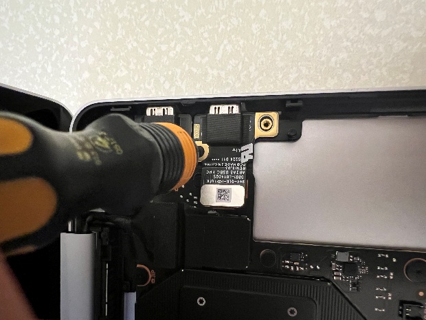
Use a 3IP Torx Plus Screwdriver to remove the two screws holding down the battery connector. Be careful as you're near the battery. Be sure to press down firmly with the screwdriver to avoid any chance for screw stripping. Additionally, please keep track and count the number of screws removed to ensure there are no extra screws in the area.
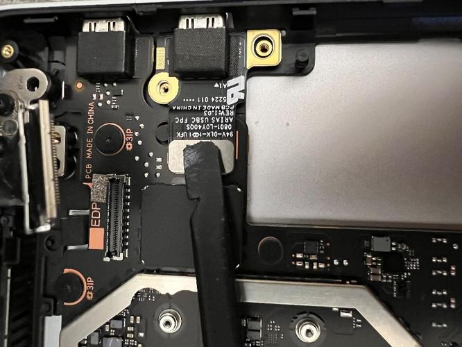
With a Plastic ESD Safe Prybar, gently disconnect the battery connector from the PCBA.
With plastic ESD safe tweezers, carefully remove the conductive tape on top of the USB-C connectors.
Use isopropyl alcohol (70% IPA) and cleaning swabs to clean any adhesive remaining on the bracket.
With a 5IP Torx Plus Screwdriver, remove the three 5IP screws holding down the USB-C bracket and remove the bracket.
Important
To avoid any chance for screw stripping, be sure to press down firmly with the screwdriver. Additionally, count and keep track of the number of screws removed to ensure there are no extra screws in the area.
With a plastic ESD safe prybar, disconnect the USB-C FPC from the PCBA.
With your fingers and plastic ESD safe tweezers, gently disconnect the right speaker connector from the PCBA and remove the right speaker.

With your fingers and plastic ESD safe tweezers, gently disconnect the left speaker connector from the PCBA.
With a plastic ESD safe prybar, disengage the bottom display connector buckle on the PCBA and gently disconnect the cable with your fingers.
With a plastic ESD safe prybar, gently lift the top display cable
With a plastic ESD safe prybar, disengage the top display connector buckle on the PCBA and gently disconnect the cable with your fingers.
Use isopropyl alcohol (70% IPA) and cleaning swabs and a plastic ESD safe prybar to clean any adhesive remaining on the top display cable.
With a plastic ESD safe prybar, disengage the USB-A and Audio Jack buckle on the PCBA and disconnect the FPC.
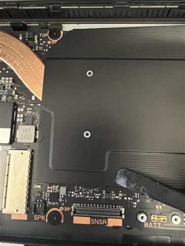
Using a 3IP Torx Plus Screwdriver, remove the seven 3IP screws on the PCBA holding it to the D Bucket. Be sure to press down firmly with the screwdriver to avoid any chance for screw stripping. Additionally, count and keep track of the number of screws removed to ensure there are no extra screws in the area.
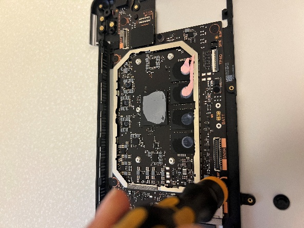
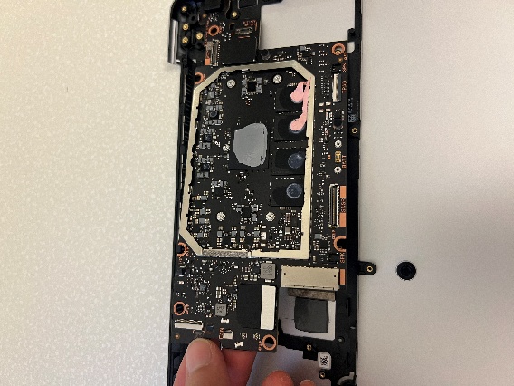
Using your fingers, gently lift up the PCBA from the left side to remove it from the D Bucket.
Procedure – Installation (PCBA)
Gently place the PCBA into the D Bucket, being careful not to scratch it against the reused connectors.
Use a 3IP Torx Plus screwdriver to lightly tighten the seven screws. Be sure to press down firmly with the screwdriver to avoid any chance for screw stripping. Additionally, please keep track and count the number of screws removed to ensure there are no extra screws in the area.
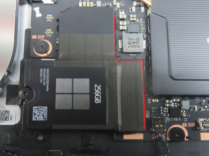
Use a feeler gauge or calipers to ensure the gap between the SSD receptacle on the PCBA and the grounding foam on the D bucket is between 0.6mm and 1.1mm. If it's not, loosen the seven screws to shift the PCBA in whichever direction is necessary to ensure the gap is within those limits before moving on to the next step.
Tighten the screws until they're snug and seated and then only tighten the screws an additional ~1/8 turn (~45 degrees) to avoid stripping the threads.
Follow “Procedure – Installation (Thermal Module)”
Follow “Procedure – Installation (AB Cover)”
Follow “Procedure – Installation (USB-C)”
Reconnect all original FPCs and connectors to the PCBA. However, replacement is necessary if there's any visible damage.
Follow “Procedure – Installation (SSD)”
Follow “Procedure – Installation (C Cover)”
Follow “Procedure – Installation (Feet)”
Download the latest SDT (surface diagnostic tool) version and follow the post-installation touch display repair (validation) and touch display (calibration), battery repair (validation), and touchpad repair (validation) workflows.
D Bucket Replacement
Preliminary Requirements
Important
Be sure to follow all special (bolded) notes of caution within each process section.
Important
This replacement part doesn't include the original serial number of the device. For future Microsoft support, write the original serial number on the label provided by Microsoft, and attach it to either the exterior of the device or directly onto an exposed part. The label included in the part's packaging has space designated for the original serial number and the part's product identifier.
Required Tools
- Soft ESD-Safe Mat or Benchtop
- Anti-static Wrist Strap (1 MOhm resistance)
- 5IP Torx Plus Screwdriver
- Plastic ESD Safe Tweezers
- Isopropyl alcohol (70% IPA) and cleaning swabs
- Plastic ESD Safe Spudger
- 0.25mm Thick Feeler Gauge
- 0.3mm Thick Feeler Gauge
- 0.05mm Thick Feeler Gauge
- New Plastic Guitar Picks
Primary Components
- 1 D Bucket Subassembly
- 1 USB-A and Audio Jack FPC Foil
- 1 USB-A and Audio Jack FPC Foam
- 1 Top Display Connector Tape
- 1 Top Display Connector Foam
- 1 Top Display Cable Tape
- 8 3IP Screws (for PCBA)
- 3 3IP Screws (for Battery)
- 5 5IP Screws (for AB Cover Hinges)
- 3 5IP Screws (for USB-A and Audio Jack Bracket)
- 2 5IP Screws (for USB-A and Audio Jack Bracket to Hinge)
- 2 3IP Screws (for USB-A and Audio Jack Daughterboard)
- 1 USB-A and Audio Jack Tape
- 1 USB-A and Audio Jack Foil
- 1 USB-A and Audio Jack Gasket
- 2 3IP Screws (for USB-C Daughterboard)
- 3 5IP Screws (for USB-C Bracket)
- 2 5IP Screws (for USB-C Bracket to Hinge)
- 1 Thermal Module Shield
- 1 CPU/Thermal Module Pad
- 6 3IP Screws (for Thermal Module)
- 4 3IP Screws (for Fan)
- 1 USB-C Tape
- 1 Fan/Thermal Module Tape
- 5 5IP Screws (for C Cover)
- 2 5IP Screws (for SSD)
- 1 Top Thermal Pad (for C Cover)
- 1 Tape (for SSD)
Procedure – Removal (D Bucket)
Follow “Procedure – Removal (PCBA)”
With your fingers, gently peel and remove the USB-A and Audio Jack FPC from the D Bucket.
Gently peel and remove the aluminum foil and foams on top of the USB-A and Audio Jack FPC.
Use isopropyl alcohol (70% IPA) and cleaning swabs to clean any adhesive remaining on the USB-A and Audio Jack FPC.
Procedure – Installation (D Bucket)
Follow “Procedure – Installation (PCBA)” Steps 1-4
Follow “Procedure – Installation (USB-A and Audio Jack)” Steps 1 and 2
Reusing the USB-A and Audio Jack FPC, align and apply the new aluminum foil and foams, as shown in the following picture.
Before pressing and installing the USB-A and Audio Jack FPC subassembly onto the D Bucket, connect the ends of the FPC to the USB-A and Audio Jack daughterboard connector and PCBA connector.
Use a plastic spudger to press the buckle on both connectors closed.
Install the USB-A and Audio Jack FPC subassembly to the D Bucket and be sure to firmly press the foil down for 30 seconds each.
Use plastic tweezers to remove the liner on the SSD thermal pad.
Follow the remaining steps on “Procedure – Installation (USB-A and Audio Jack)”
Follow the remaining steps on “Procedure – Installation (PCBA)”
Follow “Procedure – Installation (USB-C)”
Follow “Procedure – Installation (AB Cover)”
Follow “Procedure – Installation (Thermal Module)”
Follow “Procedure – Installation (Fan)”
Follow “Procedure – Installation (Speaker)”
Follow “Procedure – Installation (Battery)”
Follow “Procedure – Installation (SSD)”
Follow “Procedure – Installation (C Cover)”
Follow “Procedure – Installation (Feet)”