Exercise - Add hand interaction scripts to an object
The ObjectManipulator script supports the "direct manipulation" modality of the "hands and motion controllers" input model. When the script is attached to an object, the user can move, scale or rotate the object with their hands. In this exercise, you'll create two cubes, attach the necessary scripts to them, and then move the cubes around.
Add and adjust the first cube
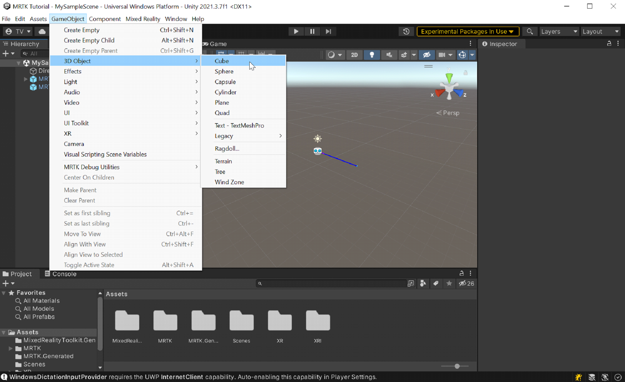
In the menu bar, select GameObject > 3D Object > Cube.
The cube's default size is one square meter, which is too large for our purposes. We'll scale the size down to 20x20x20 centimeters.
Select the cube, and then in the Inspector, change the cube's Transform/Scale values to the following:
X = 0.2, Y = 0.2, Z = 0.2
The cube was placed in the scene at the default position of (0,0,0). This means the cube is at the same position as the user's headset, and the user won't be able to see the cube until they move backwards. We'll change the cube's position values so it'll be in a better location for viewing.
In the Inspector, change the cube's Transform/Position values to the following:
X = -0.2, Y = 1.6, Z = 0.5
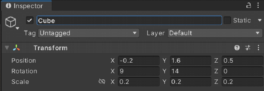
We want to be able to see three sides of the cube, so we'll change the cube's rotation, too.
Note
The height of the cube is set to 1.6 to match the height of the Camera Offset on MRTK XR Rig, placing it roughly at eye level.
In the Inspector, change the cube's Tranform/Rotation values to the following:
X = 9, Y = 14, Z = 0 f
Tip
To zoom in on the cube, select it, make sure cursor is hovering over the Scene window, then press the F key. You can zoom in on any object this way.
Add the scripts to the cube
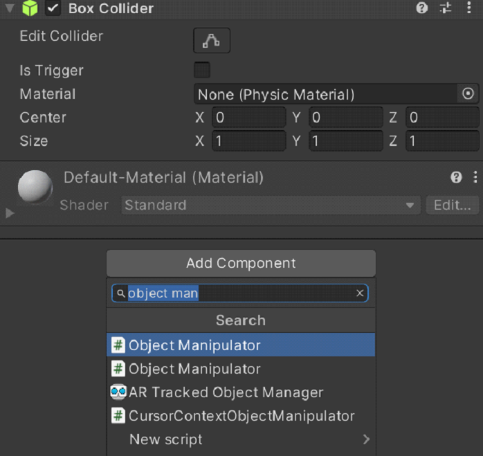
In order for an object to be "grabbable" with tracked hands, it must have two components attached:
- A Collider component (You don't need to do anything here; Unity's cube already has a Box Collider attached by default)
- Object Manipulator (Script) component
With the cube still selected, in the Inspector window, select the Add Component button, and then search for and select the Object Manipulator script.
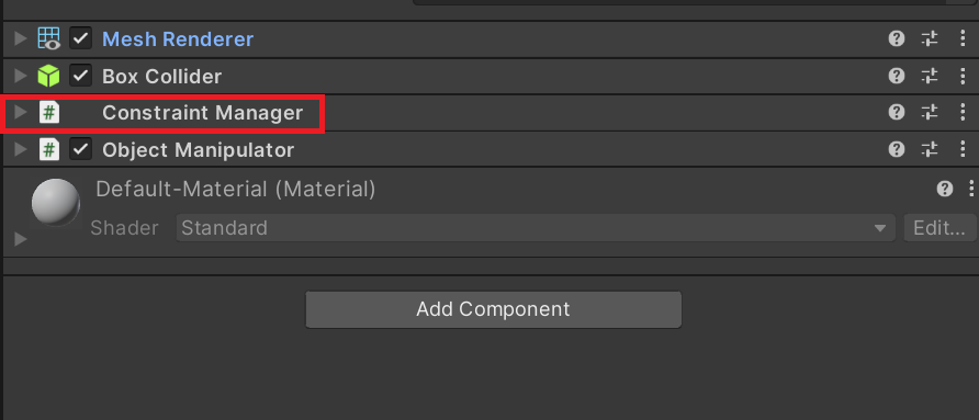
The ObjectManipulator script makes an object movable, scalable, and rotatable using one or two hands. When you add the Object Manipulator script, the Constraint Manager script is automatically added as well because the Object Manipulator script depends on it.
Update the cube's material
For performance purposes, we recommend using MRTK materials instead of the default Unity materials.
- With the cube still selected, find the Materials section on the Mesh Renderer component.
- Replace the default material with the MRTK_Standard_White material, located under MRTK Standard Assets > Materials. You can drag and drop the material from the Project pane into the Materials section.
Add a second cube
In the Hierarchy, right-click the cube and select Duplicate. The duplicated cube appears with the name Cube (1).
Right-click the original cube, select Rename, and name the cube Near Cube.
Right-click the duplicated cube, select Rename, and name the cube Far Cube.
At the moment, it looks like there's only one cube in the Scene view. That's because Near Cube and Far Cube are in the same exact place. Let's change Far Cube's position and rotation.
With Far Cube still selected, change its values in its Transform component to the following:
Position: X = 0.6, Y = 1.6, Z = 1.1
Rotation: X = 27, Y = 0, Z = 0
Now the camera should see Near Cube on the left and Far Cube a little further away on the right. To confirm this, in the Hierarchy, select Main Camera (under MRTK XR Rig > Camera Offset) and then look at the Main Camera window in the Scene window.
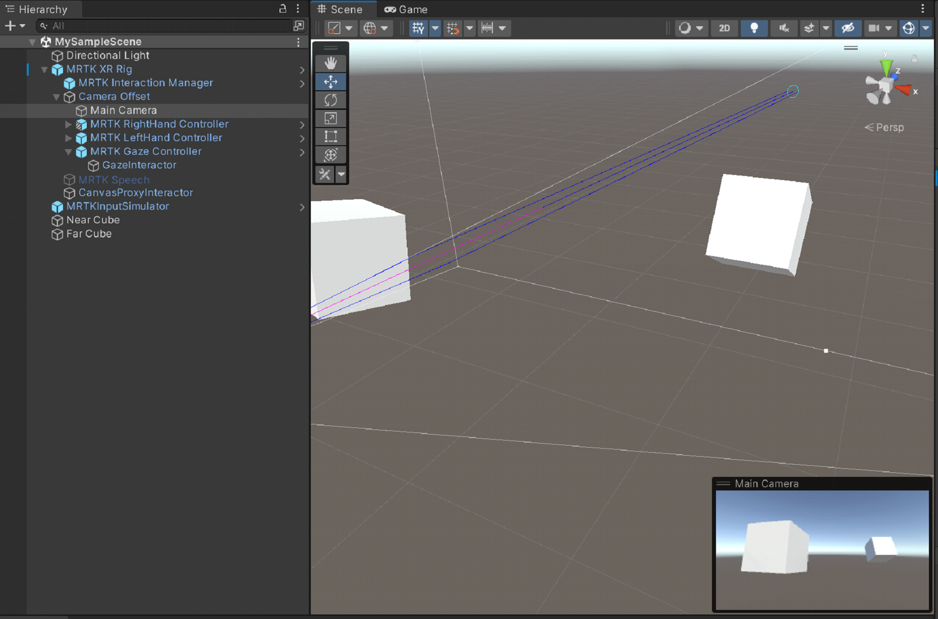
Tip
If you want the view in the Scene window to look more like what the camera sees, scroll around in the Scene window. You might have to set the camera's Clear Flags to Skybox if it isn't by default.
Grab and move the cubes in Play mode
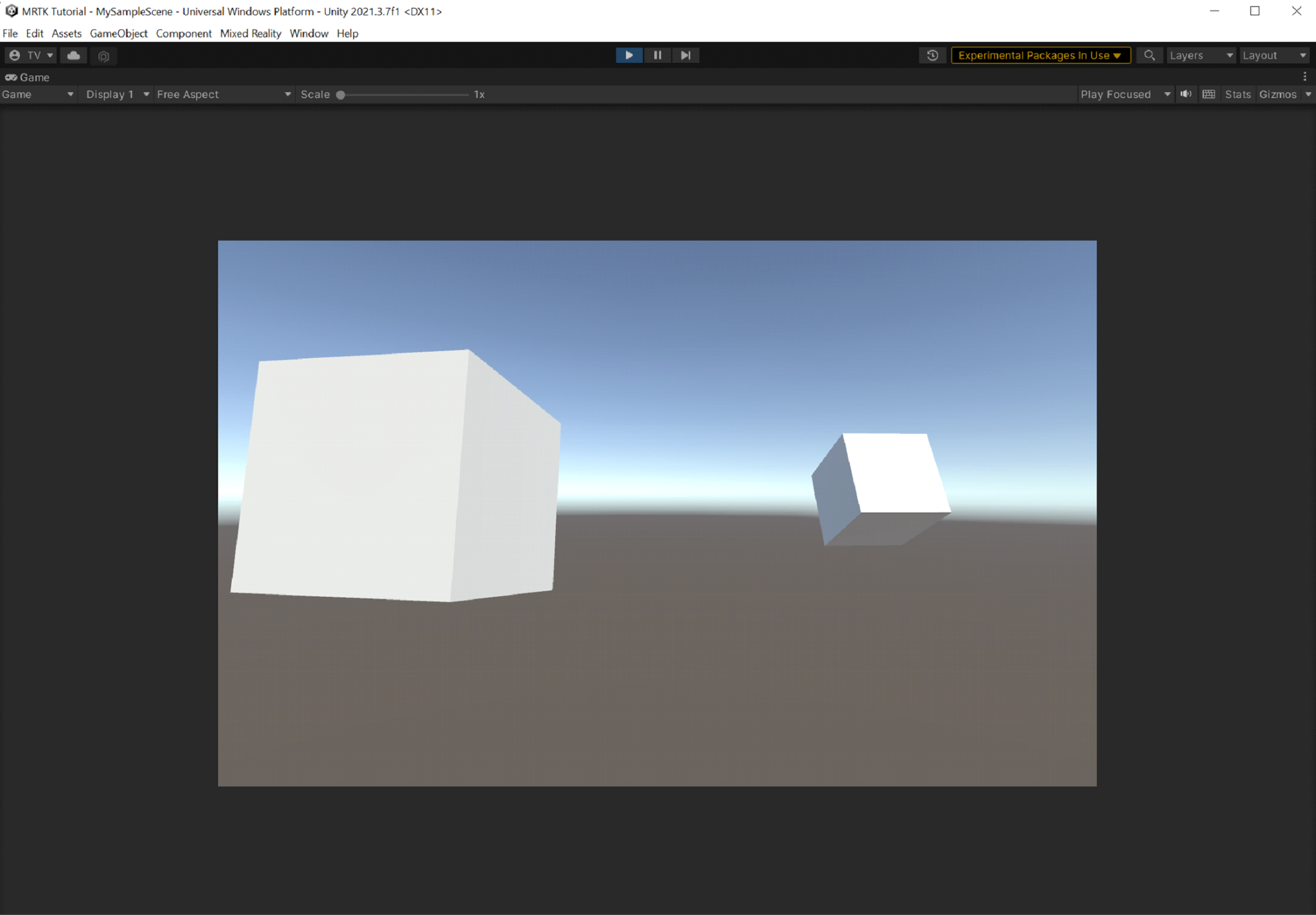
Select the Play button. When the project starts playing, the view switches to the Game window.
Note
Before Playing, confirm that there's a valid Profile set under Project Settings > MRTK3.
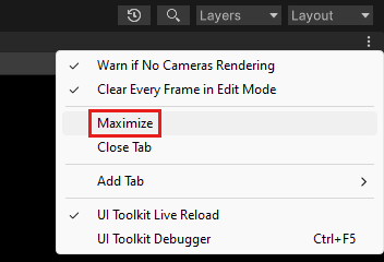
Select the three-dot button in the upper-right corner of the Game window and select Maximize.
Press the space bar to make the simulated right hand appear in the view.
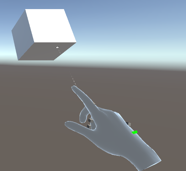
Move the simulated hand closer to Near Cube until it touches the cube on the side or bottom.
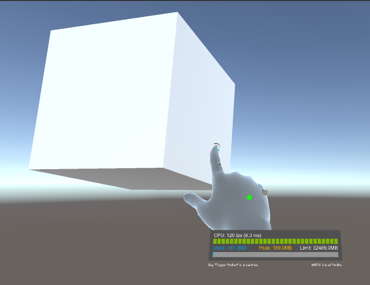
Press the left mouse button (this makes the hand "grab" the cube) and drag the cube around the scene.
To grab and move Far Cube, we'll use the far pointer attached to the simulated hand.
If you need to, press the space bar again to make the simulated right hand appear. Note the far pointer that extends from the end of the hand's index finger.
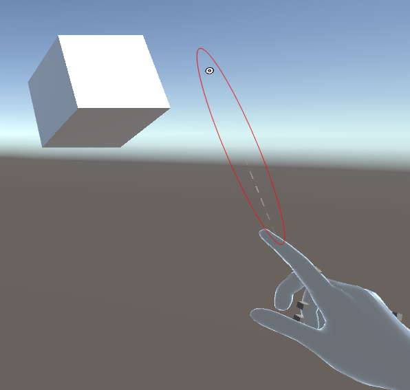
Move the hand closer to Far Cube until you can see the tip of the pointer on the cube. You might have to move the hand around in a circular motion a few times to make the tip of the pointer appear on the cube.
Press the left mouse button (this makes the hand close, taking on what we call the pinch gesture) and drag the cube around the scene.

Unity in-editor input simulation
You can test holographic object behavior with the Unity in-editor input simulation features.
Change the view in the scene
- To move the camera forward/left/back/right, press the W/A/S/D keys.
- To move the camera vertically, press the Q and E keys.
- To rotate the camera, press the right mouse button and then drag.
Simulate hand input
- To enable the simulated right hand, press and hold the space bar. To remove the hand, release the space bar.
- To enable the left simulated hand, press and hold the left shift key. To remove the hand, release the key.
- To move either hand around the scene, move the mouse.
- To move the hand forward or backward, rotate the mouse scroll wheel.
- To simulate the pinch gesture, press the left mouse button.
- To rotate the hand, press and hold down the space bar + CTRL key (right hand) or left shift key + CTRL key (left hand) and then move the mouse.
Persistent hands
To enable a hand and keep it onscreen without continuing to hold down a key, press T (left hand) or Y (right hand). To remove the hands, press those keys again.
Build your application in Unity
Minimize the Play window by selecting the three-dots button, then unchecking Maximize.
In the menu bar, select File > Build Settings....
In the Build Settings window, select the Add Open Scenes button to add your current scene to the Scenes In Build list.
Select the Build button.
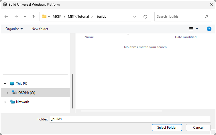
In the Build Universal Windows Platform window, navigate to the folder where you want to store your build, or create a new folder and navigate to it, and then select the Select Folder button to start the build process.
A progress bar appears to let you know how the build is proceeding.
(Optional) Build and deploy the application
Note
Building and testing on HoloLens 2 is not mandatory. Alternatively, you can test on the HoloLens 2 Emulator if you don't have a device. You can purchase devices at HoloLens.com.
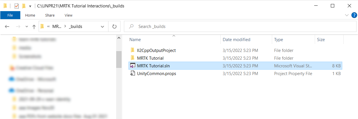
When the build process has completed, Windows File Explorer opens and displays the build folder. Navigate inside the folder and double-click the solution file to open it in Visual Studio.
Configure Visual Studio for HoloLens by selecting the Master or Release configuration and the ARM64 architecture:
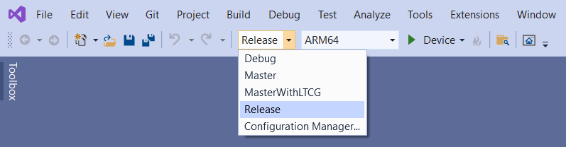
Tip
If you're deploying to HoloLens (1st generation), select the x86 architecture.
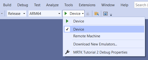
Note
If you don't see Device as a target option in Visual Studio, you might need to change the startup project for the solution from the IL2CPP project to the UWP project. In the Solution Explorer, right-click [your project name](Universal Windows) and select Set as StartUp Project.
Important
Before building to your device, the device must be in Developer Mode and paired with your development computer.; see Enabling Developer Mode.
Select the deployment target drop-down and then do one of the following:
- If you're building and deploying via Wi-Fi, select Remote Machine.
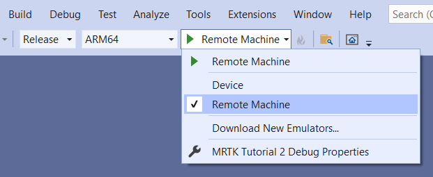
- If you're building and deploying via USB, select Device.
Set your remote connection: on the menu bar, select Project > Properties.
In the project's Property Pages window, select Configuration Properties > Debugging.
Select the Debugger to launch drop-down and then select Remote Machine if it's not selected already.
Important
We recommend that you manually enter your IP address rather than depend on the "Auto Detected" feature. To find your IP address, on your HoloLens, go to Settings > Updates & Security > For developers. The IP address is listed towards the bottom of the window under Ethernet.
In the Machine Name field, enter your device's IP address.
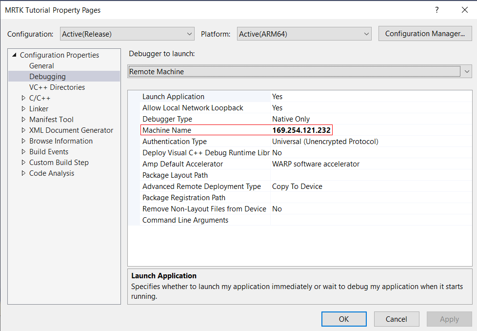
Set the Authentication Mode to Universal (Unencrypted protocol).
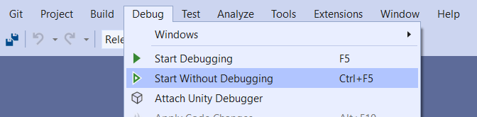
Connect your HoloLens to your computer, then do one of the following in Visual Studio:
- To deploy to your HoloLens and automatically start the app without the Visual Studio debugger attached, select Debug > Start Without Debugging.
- To deploy to your HoloLens without having the app start automatically, select Build > Deploy Solution.
Pairing your device
The first time you deploy an app to your HoloLens from your PC, you'll be prompted for a PIN. To create a PIN:
- In your HoloLens, go to Settings > Updates & Security > For developers.
- Select Pair. This displays the PIN in the HoloLens.
- Enter the PIN in the dialog in Visual Studio.
- After pairing is complete, select Done in the HoloLens.
Your PC is now paired with your HoloLens, and you can deploy apps automatically. Repeat these steps for every PC that's used to deploy apps to your HoloLens.
Running your app on your HoloLens
After your app finishes building, in the HoloLens Start menu, find the app tile for your app, then select it.
After the app starts, reach out to the Near Cube, then grab it and drag it around.
Use the far pointer to grab the Far Cube, then drag it around.
Tip
The HoloLens gives you more flexibility than when you were testing your app in Unity. You can physically move around and use the far pointer on the Near Cube or reach out and grab the Far Cube with your hand!
Tips
You can also deploy to the HoloLens Emulator or create an App Package for sideloading.
You might notice the Diagnostics profiler in the app. You can toggle it on or off by using the speech command Toggle Diagnostics. We recommend that you keep the profiler visible most of the time during development so you can understand how changes to the app might affect performance. For example, you can monitor your app to ensure that the frame rate is at least 60 FPS.