Note
Access to this page requires authorization. You can try signing in or changing directories.
Access to this page requires authorization. You can try changing directories.
Starting with Windows 8, system hardware designers can choose between two different hardware topologies for the battery and power subsystems in their Windows platforms.
Hardware topologies
Generally, Windows expects one of two hardware topologies for the power and charging subsystem.
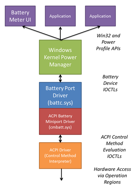
The first topology is shown in the following block diagram. This topology, which is common in PCs that run Windows 7, uses an embedded controller in the platform. The embedded controller typically performs multiple functions in a mobile Windows PC, including power source control, battery charge management, power button/switch detection, and PS/2-compatible keyboard and mouse input. The embedded controller is typically connected to the core silicon through the Low Pin Count (LPC) bus. Windows queries and is notified about power subsystem information through the ACPI embedded controller interface.
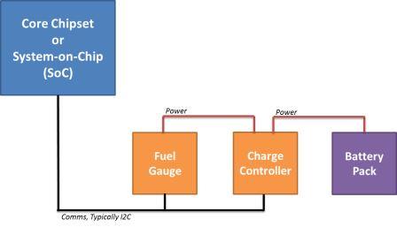
The second topology is shown in the following block diagram. This topology uses a battery charge controller and fuel gauge component, which are connected directly to the platform's core silicon over a simple peripheral bus, such as I²C. In this configuration, Windows queries and is notified about power subsystem changes through communications over the I²C bus. A Simple Peripheral Bus (SPB) operation region enables ACPI control method code in firmware to communicate to the battery charge controller and fuel gauge components that are connected to the core silicon over an I²C bus.
ACPI operation with an embedded controller
Platforms that have their battery and power subsystem connected to the typical platform embedded controller use the ACPI embedded controller operation region to facilitate communications between the ACPI control method environment and the platform hardware.
The ACPI firmware must define the embedded controller in the ACPI namespace. This definition includes the following:
- A Device() node for the embedded controller.
- A _HID object that indicates the device is an embedded controller.
- A _CRS object to denote the I/O resources for the embedded controller.
- A _GPE object that defines the SCI for the embedded controller.
- An operation region that describes the information that is contained in the embedded controller that can be accessed by other ACPI control method code in the namespace, including battery status and information methods.
For more information, see section 12.11, "Defining an Embedded Controller Device in ACPI Namespace", in the ACPI 5.0 specification.
Accessing battery information from the embedded controller
ACPI control methods access information from the embedded controller by reading the values that are described in the embedded controller's operation region.
Notifying Windows when battery state changes (embedded controller)
When the embedded controller detects a change in battery state, including a change in charging state or remaining capacity as specified by _BTP, the embedded controller generates an SCI and sets the SCI_EVT bit in the embedded controller status command (EC_SC) register. The Windows ACPI driver, Acpi.sys, communicates with the embedded controller and issues a query command (QR_EC) to request specific information about the notification to be issued. The embedded controller sets a byte value corresponding to the _QXX method to be executed. For example, the embedded controller and ACPI firmware can define value 0x33 to be an update to battery status information. When the embedded controller sets the value 0x33 as the notification, Acpi.sys will execute the _QXX method. The _QXX method typically issues a Notify(0x80) command on the Control Method Battery device in the namespace.
Power consumption
Special care must be taken on modern standby systems to ensure that minimum battery life goals for modern standby are achieved. On modern standby systems, the nominal power consumed by the embedded controller for power and battery subsystem must be below 5 milliwatts. On PCs that use the traditional S3/S4 power states, make sure that the embedded controller does not impact battery-life goals. There are no specific nominal power requirements for systems that use S3/S4.
ACPI operation with an SPB-connected charging subsystem
Platforms can also connect the battery and power subsystem connected to the core chipset by using a low-power simple peripheral bus (SPB) such as I²C. In these designs, the ACPI GenericSerialBus operation region is used to communicate between ACPI control methods and battery subsystem hardware. Connecting the battery subsystem hardware to a GPIO interrupt allows ACPI control methods to be executed when battery status changes.
When the battery and power subsystem hardware is connected by using I²C, ACPI firmware must define the following:
- A Device() node for the GPIO controller device to which the I²C interrupt is connected, including:
- _HID object describing the hardware ID of the GPIO controller.
- _CSR object describing the interrupt and hardware resources of the GPIO controller.
- _AEI object that maps one or more GPIO lines to ACPI event method execution. This enables ACPI methods to be executed in response to GPIO line interrupts.
- A Device() node for the I²C controller to which the battery fuel gauge and charging hardware are connected, including:
- _HID and _CSR objects that describe the hardware ID and resources of the I²C controller.
- A GenericSerialBus operation region within the scope of the I²C device that describe the virtual command registers for the I²C device.
- Field definitions in the GenericSerialBus operation region. The field definitions allow ASL code outside of the I²C device to access the virtual command registers for the I²C device.
Describing the GPIO controller and mapping of GPIO lines to ACPI events enables control methods for battery status and notification to be executed when a GPIO interrupt from an I²C device is raised. Describing the GenericSerialBus operation region allows ACPI code for battery status to communicate over the I²C bus and read registers and information from the battery fuel gauge and charging subsystem.
Accessing battery information from the charging subsystem
Battery status can be executed by ACPI control methods by sending and receiving commands over the I²C bus to which the battery subsystem hardware is connected. The control method code backing the status and battery static information methods reads and writes data from GenericSerialBus operation regions described in the ACPI namespace. The control method code can read data from the fuel gauge device or static information about the battery capacity and cycle count over the I²C bus through the GenericSerialBus operation region.
Notifying Windows when battery state changes (subsystem hardware)
The battery subsystem hardware can generate an interrupt when state changes, or from a GPIO line on the core silicon. The GPIO line can be mapped to a specific control method execution by using the _AEI object under the GPIO controller described in ACPI. When the GPIO interrupt occurs, the Windows ACPI subsystem executes the method associated with the specific GPIO line, which can in turn issue a Notify() command on the Control Method Battery device. This causes Windows to re-evaluate status and static information methods to update battery status.
Power and charging indicators
Windows provides indication of power source and battery status in the operating system. This is presented to the user in several places, including the battery tray icon on the desktop, on the Start menu, and directly on the Lock screen.
Windows 8 platforms can also present a visible indicator to the user of charging status. The following figures show two UI examples. The indicator that is used must have little impact on power consumption and the user experience.
Windows power and charging user interface elements
Windows provides an indication of power source and charging status in three key locations:
- On the lock screen. A battery icon with power source and charge status is displayed.
- On the time-and-date indicator when hovering over the Start button. A battery icon with power source and charge status is displayed.
- Battery icon on the desktop. A battery icon with power source and charge status is displayed. More information is available when you click on the battery icon; this includes capacity remaining, estimated time remaining, and per-battery details if the system has multiple batteries
. For modern standby-capable platforms, if the system is in S0 and the lid (if present) is not closed, Windows briefly lights up the display when the system is connected to the charger and power is applied. This enables users to see the platform respond to the action of connecting the charger.
Platform hardware charging indicators
The user interface elements that are built into Windows address the scenarios where Windows is running and the display is visible to the user. However, these on-screen indicators are not visible when the system is shutdown, hibernated, sleeping, or otherwise not running.
A platform may include an LED to indicate that power is present. It is preferred that such an LED not be placed on the system chassis. Instead, the LED it should be either on the power brick, power cable, or power connector. Optionally, this LED can also indicate charge status to the user.
If an LED is provided, it should not vary in intensity or color over time or otherwise flash or blink, because that presents a distraction to users. It may however change color to indicate charge status; for example, yellow when charging, green when fully charged, or red when a failure occurs.
Real-time clock reserve battery capacity
Maintaining accurate time is essential to delivering a great user experience. In addition, accurate time is required to connect to services such as the Microsoft Store. All Windows systems should maintain accurate time for a period of at least four weeks, even when off. Typically this is done by employing a separate backup battery to maintain the real-time clock (RTC). This is not always possible or practical on highly portable form-factors.
System designers can use a dedicated battery or reserve a portion of the main system battery. Given the modest power requirements of the RTC, a relatively low reserve threshold will provide guarantees that match dedicated backup batteries that exist in today's PCs.
Design guidelines
OSPM provides a method for system designers to override the Windows OS critical battery event. When the battery gets to a critical level (in milliwatt-hours), as defined by the _BIX (Battery Information Extended – Design Capacity for Low) method in the Control Method Battery implementation, the firmware issues a Notify command to the OS. At that point, Windows will perform an emergency shutdown or hibernate to preserve system state.
All designs must meet the following requirements:
- The Design Capacity for Low in the _BIX method must be set to at least 675 milliwatt-hours of the full design capacity (in addition to the capacity necessary to reliably perform the critical action).
- The reserve capacity above must be less than four percent of the full design capacity.
Charging performance
The time required to fully charge the system battery is a concern to the user. Many systems are charged overnight or during other periods when the user is not interacting with the system. However, when the battery is fully drained and the user wants to use the system in a portable fashion, charging performance is a primary concern.
Windows recommends that all platforms be capable of charging the system battery from 5 percent to 90 percent within four hours or less when the system is booted and in modern standby with the screen off.
System designers should pay special attention to charge rate for systems that support Universal Serial Bus (USB)-based charging only. Systems that have USB charging only and large battery capacity might not meet the customer's expectation for charging performance.
If USB charging is required on platforms with large battery capacity (greater than 30 watt-hours), the system designer should also provide a high-power DC input and bundle a high-power DC charger with the system. This also enables the platform battery to be charged during interactive use, which might otherwise be impossible given the low input power and high power consumption of a USB charge-only platform with large battery capacity.