Note
Access to this page requires authorization. You can try signing in or changing directories.
Access to this page requires authorization. You can try changing directories.
Windows 10 Guidelines
This topic covers guidelines for Touch display components in Windows 10.
Touch requirements
The following table lists Windows 10 features related to touch.
| Desktop and mobile use same input platform |
|
| Touch experience significantly improved |
|
| Lower requirements that complement Windows 10 touch experiences |
|
The following table lists requirements for touch-related attributes:
| Attribute | Windows 10 Requirements |
|---|---|
| HID Compliance | Required |
| Ghost Points | No ghost contacts are reported |
| Accuracy | <= +/- 1mm (outside 3.5mm from edges) <= +/- 2mm (within 3.5mm of all edges) |
| Move Latency | For <7”, <= 35ms For >=7”, <=25ms |
| Down Latency (Active) | <= 35ms |
| Down Latency (Idle) | <= 150ms |
| Cold Boot Latency | Immediately responsive once the display is active |
| Resolution | >= Native display resolution or greater |
| Linearity (Moving jitter) | <= +/- 1mm (outside 3.5mm from edges) <= +/- 2mm (within 3.5mm of all edges) |
| Stationary Jitter | <= 0.5mm |
| Finger Separation | <= 8mm [Edge to Edge] |
| Minimum Simultaneous Contacts | >= 5 |
| Buffering | >= 100ms of data |
| Report Rate | >=Display Refresh Rate <=250Hz |
| Custom Gestures | Custom gestures designed to work with user interface elements are prohibited |
| Third party drivers | Desktop: Third party drivers prohibited Mobile: Third party drivers allowed |
Touch implementation
Drivers
- Drivers built for Windows 8.1 phone and desktop continue to work on the updated touch platform
- Driverless, firmware-based solutions ensure that touchscreens always work
- These solutions will be seamlessly upgraded to Windows 10
Compatibility
- Desktop touch devices previously certified for Windows 8 and Windows 8.1 are automatically fully compatible
- Mobile devices that met the chassis spec guidelines need to be re-tested
- Touch solutions are backed with a hardware compatibility program that ensures a great experience
TEST JIGS FOR TOUCH HLK
Most touch tests are identical to the existing test for Windows 8.1, with upgraded parameters:
Existing testing tools from Windows 8 and Windows 8.1 are still used for Touch tests:
- Precision Touch Testing Tool (PT3)
- Rotational Acoustic Tool (RA)
Windows 10 accessory jigs to enable Touch testing:
- 7mm slugs
- 16mm slug
Maintained guidelines from Windows 8.1
Display surface
The following guidelines are provided to create a successful touch experience on touch-enabled displays.
Use glass or glass coatings designed to reduce fingerprints.
Consider anti-glare materials and LED-based illumination to ensure screen readability in outdoor and brightly lit indoor environments.
Choose an anti-glare material with the following characteristics:
- Low haze value (<=6%) to minimize reduction of display clarity and contrast while providing minimal friction.
- Finer than the sub-pixel pitch to prevent sparkling.
Minimal surface friction (surface roughness of 100-500 nm (RMS). High surface friction causes the finger to skip over the surface, breaking touch contact.
Device cover glass
This section defines the functional attributes for device cover glass that provides the user with a high quality touch-screen experience worthy of the Microsoft brand. Attributes include those that preserve and protect the surface, appearance, and device, and improve the touch functional experience.
Cover glass for discrete applications
Discrete cover glass applications use the glass as a protective display cover on top of the touch sensing layer, but not as a physical carrier or substrate for the touch sensing layer (ITO, etc.) itself. You should conduct all tests and measurements following the conditions outlined in Cover Glass Test and Measurements.
For optimal damage resistance:
The cover glass should be chemically-strengthened with a minimum magnitude and depth of layer (DOL) of the compressive stress as follows. In all cases, glasses should exhibit non-frangible behavior. Frangible behavior is when the glass breaks into a large number of small pieces when hit with sufficient force:
- 0.55 mm: ≥ 700 MPa CS and > 35 microns DOL
- 0.7 mm: ≥ 750 MPa CS and > 40 microns DOL
- 1.0 mm: ≥ 750 MPa CS and > 45 microns DOL
4-point bend test performance (edge strength) recommendations:
- 0.55 mm: Average peak stress = 600 MPa
- 0.7 mm: Average peak stress = 620 MPa
- 1.0 mm: Average peak stress = 620 MPa
Abraded ring-on-ring test performance (surface strength) recommendations:
- 0.55 mm: Average load-to-failure = 30 kgf
- 0.7 mm: Average load-to-failure = 55 kgf
- 1.0 mm: Average load-to-failure = 100 kgf
The following general design guidance should apply to machined cover glass parts:
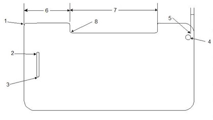
# Feature Measure Guidance 1 Outer corner Radius > 1.0 mm 2 Slot radius Radius > 1.5 mm 3 Slot width Width > 1.5 mm 4 Min. hole diameter Diameter > 1.5 mm 5 Hole-to-edge distance Diameter > 4.0 mm 6 Width of protrusion Width Width > Depth 7 Width of the slot Width Width > Depth 8 Inner radius Radius > 1.0 mm Note Tests conducted using a standard 1mm glass.
The indentation threshold as measured with a Vickers indenter should be ≥ 5* kgf.
The Knoop scratch load to lateral cracks should be ≥ 4* N.
High-Quality Touch Experience Recommendations:
- Minimum dielectric constant is 7.0.
- The Young's Modulus of the glass should be 71.5±5 GPa.
- The coefficient of thermal expansion (CTE) should be 80±4 x 10⁻⁷ per degree C.
- Water absorption should meet Hydrolytic Resistance Class 2 or better.
High-Quality Viewing Experience Recommendations:
- Optical transmission as measured through 1.0 mm thick cover glass is >91% nominal transmission across the 390-760 nm (visible) wavelength spectrum, with variation not to exceed ±1%.
Cover glass for integrated touch applications
Integrated touch cover glass applications are glass covers that serve as a protective display cover and as a physical carrier or substrate for the touch sensing layer (ITO, etc.) itself. Integrated touch cover glass applications are also known as one-glass solutions (OGS). You should conduct all tests and measurements following the conditions outlined in Cover Glass Test and Measurements.
Optimal Damage Resistance Guidelines:
The cover glass should be chemically-strengthened with a minimum magnitude and depth of layer (DOL) of the compressive stress (CS) as follows. In all cases, glasses should exhibit non-frangible behavior. Frangible behavior is when the glass breaks into a large number of small pieces when hit with sufficient force:
- 0.55 mm: ≥ 500 MPa CS and > 25 microns DOL
- 0.7 mm: ≥ 550 MPa CS and > 37microns DOL
- 1.0 mm: ≥ 550 MPa CS and > 55 microns DOL
4-point bend test performance (edge strength) recommendations:
- 0.55 mm: Average peak stress = 600 MPa, B10 > 450MPa
- 0.7 mm: Average peak stress = 620 MPa, B10 > 500MPa
- 1.0 mm: Average peak stress = 620 MPa B10 > 500MPa
Abraded ring-on-ring test performance (surface strength) recommendations:
- 0.55 mm: Average load-to-failure = 13 kgf
- 0.7 mm: Average load-to-failure = 20 kgf
- 1.0 mm: Average load-to-failure = 29 kgf
Refer to the figure for the machined cover glass part for general design guidance on machined cover glass parts. Holes and/or slots are not recommended on cover glass used for integrated touch applications due to compromises in edge strength.
The indentation threshold as measured with a Vickers indenter should be ≥ 5 kgf.
The Knoop scratch load to lateral cracks should be ≥ 4 N.
High-Quality Touch Experience Guidelines:
- Minimum dielectric constant is 7.0.
- The Young's Modulus of the glass should be 71.5±5 GPa.
- The coefficient of thermal expansion (CTE) should be 80±4 x 10⁻⁷ per ºC.
- Water absorption should meet Hydrolytic Resistance Class 2 or better.
High-Quality Viewing Experience Guidelines:
- The recommended optical transmission as measured through 1.0 mm thick cover glass is >91% nominal transmission across the 390-760 nm (visible) wavelength spectrum, with variation not to exceed ±1%.
Cover glass tests and measurements
Make all measurements on bare glass with no coatings, films, or other types of surface treatments applied.
Conduct all tests in a controlled environment (23±2º C, 50±5% RH).
4-Point Bend
Perform horizontal bending testing using 18mm loading spans, and 36mm support spans applying a nominal crosshead rate of 5mm/min. The preferred sample geometry is 44mmx60mm. Breaking stress is reported based on ASTM C158. Sample geometries beyond the preferred geometry may require consultation by Corning on span selection.
Abraded Ring-on-Ring (AROR)
Abrasion with 90 grit Silicon Carbide @ 5psi, 5 seconds, ¼" mask; retained strength measured through Ring on Ring, ½" load ring, 1" support ring. Nominal crosshead rate of 1.2mm/min. Center the abrasion on the glass sample and place it in the center of the loading ring for testing. Breaking load is reported. The preferred sample geometry is 50mmx50mm. You can use ASTM C1499 as a reference for some aspects of the ring on ring procedure.
Indention
A Vickers indenter makes a series of indents in a glass samples, stepping through a range of repeated loads and held at the maximum load for 10 seconds, samples are inspected to assess the load where >50% of the indents exhibit evidence of radial cracks after a fixed period of time once the indents have been created. Loading/unloading rates = 0.2mm/min.
Scratch Threshold
A Knoop indenter places a series of 10mm scratches in a sample. Repeated scratches are performed over a range of loads, samples are inspected to assess the load where >50% of the scratches exhibit evidence of lateral cracks after a fixed period once the scratches have been created.
Related topics
Human Input Devices Design Guide