Note
Access to this page requires authorization. You can try signing in or changing directories.
Access to this page requires authorization. You can try changing directories.
This is a test to check the time lag (latency) between the Windows pen being in a new screen location, and when that new location is reported to Windows.
Test name
- Move Latency
Core requirements tested
- Device.Input.Digitizer.Pen.Latency – Move Latency
Test purpose
- Verifies that while the pen is in contact with the screen, the lag between the pen being at a location and having the location reported to Windows, is within allowed limits.
Tools required
- RA Tool with Pen holder + 150g weight.
- Zip ties are needed, if you purchase Triex pen test kit.
Validation steps
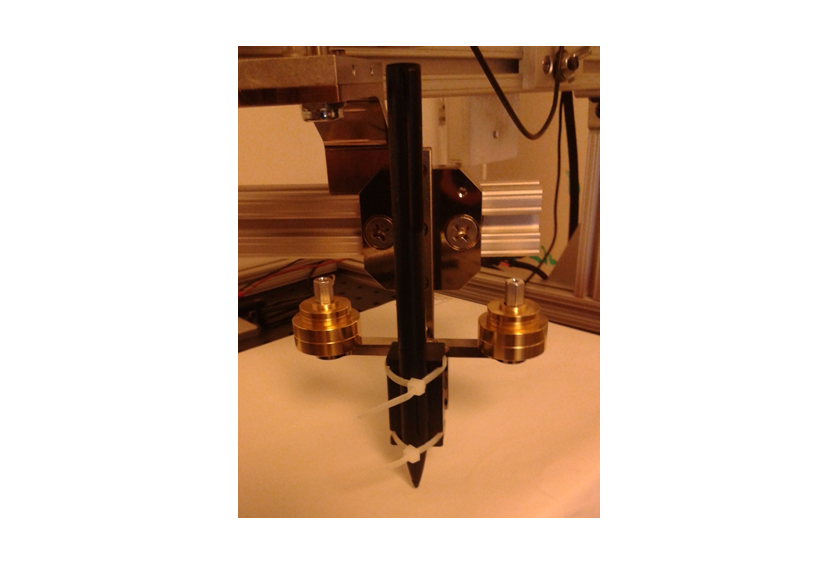
Make sure that the RA tool is fitted with the Pen Holder, and attach the pen to the pen holder with zip ties. Ensure that none of the barrel buttons are activated when the pen is in the pen holder. The Triex RA tool with the pen attached to the pen holder, is shown in the following image:
Plug the RA tool control box into the test machine, and then turn on the control box. The control box might end up in a weird state if this is done in a different order. Set the switches on the control box as follows:
- Motor: Off
- Calibrate: Off
- Mode: Tachometer
Adjust the radius of the circle to approximately 23-25 mm and position the device, so that the contact will stay on the digitizer surface during its full rotation. The pen should be placed close to the center of the screen.
- To make it simpler to verify the radius of the circle, open MSPaint on the device, bring the pen into contact with the screen, and perform a full rotation of the pen. You can measure the circle drawn by the pen with a ruler to determine the radius.
Rotate the arm until the notch on the disk is 2-3mm past the photo-interrupter.
- If it is too close to the photo-interrupter, you will get an extra data point at the beginning of the test. This is because when started, the motor will jerk backwards. If the notch falls under the photo-interrupter during this, it will cause erroneous data.
- If it is too far from the photo-interrupter, count will seem to increment by 2, instead of giving 2 increments of 1. The motor is calibrated to rotate around and pass slowly for a certain segment of the circle relative to where it started, and that slow section is expected to pass under the photo-interrupter. But if it starts too far away from the photo-interrupter, the arm will still be moving too quickly when the notch passes under the photo-interrupter.
Run test for pen move latency.
Lower the contact onto the surface.
Press the Spacebar on the test machine and flip the Motor switch to on to begin the Calibration phase.
After 9 rotations (when Count on the screen equals 17), the motor will come to a complete stop for 5 seconds. Press the Spacebar during those 5 seconds to advance to Acquisition phase.
Wait for 10 rotations of the arm, then press the Spacebar to move onto the Collection phase.
After the arm has made 10 rotations in the Collection phase, press the Spacebar one last time to close the test, and then switch off the motor.
Note Unless there's an error, do not exit the test by pressing ESC, otherwise the test might not finish running.
Common errors
At the beginning of the Calibration stage, if the slot on the disk is too close to the photo interrupt signal, the calibration text will appear with a count of zero (0) before the arm has rotated once. To avoid this issue, do the following:
- Be sure to position the slot 2-3mm past the photo interrupt signal.
When calibration executes correctly, the count should increment by 2 every rotation: once before, and once after hitting the photo interrupt signal.
- Because of this, the pause before the beginning of the Acquisition stage always occurs when the count = 17.
- If the count isn’t incrementing properly, abort the test. Turn off the control box, unplug and re-plug the control box into the test machine via USB, then turn the control box on again. Start the test from the beginning, and verify that the count is incrementing correctly.
Note A correctly incrementing count should start at 1, and increment by 2 each rotation cycle until the count hits 17.
At the end of the Calibration stage, the motor will pause completely for 5 seconds. During that pause, the space bar must be hit to advance to the Acquisition stage, otherwise an error message will be displayed.
Passing criteria
- 10 rotation cycles must be collected with a passing average pen move latency for test success.
- This test has a 6ms allowed tolerance, therefore an average pen move latency of <= 36ms will result in a pass.