Note
Access to this page requires authorization. You can try signing in or changing directories.
Access to this page requires authorization. You can try changing directories.
The following section details guidelines for OEMs selecting components such as presence sensors to support the inbox device experiences detailed above. It covers both the general requirements for all sensors in addition to the specific guidance for particular device experiences. Presence sensors are proximity sensors of type "Human". Review the device experiences and terms for Presence sensing before reading this section.
This section is intended to provide guidance for OEMs looking to install presence sensor hardware on a system. These guidelines represent a minimum viable sensor setup. Microsoft encourages installing hardware that outperforms the standards here.
The range, latency, distance, and power will not be measured by Microsoft but OEMs and ODMs should validate functionality in accordance with HLK requirements. If the system reports distance, its accuracy should be measured.
Important design details and general requirements for all human presence sensors
If a proximity sensor supports human presence, then it must support the detection type:
DEFINE_PROPERTYKEY(DEVPKEY_Sensor_HumanPresenceDetectionType,0xd4247382, 0x969d, 0x4f24, 0xbb, 0x14, 0xfb, 0x96, 0x71, 0x87, 0xb, 0xbf, 81); //[VT_UI4]
Currently defined detection types are found below:
| Usage name | Usage type | Usage description |
|---|---|---|
| Human presence detection type: Vendor-defined non-biometric | Sel | Presence (of one or more people) is detected utilizing a vendor-defined, but non-biometric method. This is used to give positive affirmation that the sensor is using detection unrelated to biometrics as defined below. Without this, a Host cannot assume biometrics aren't utilized by the device. |
| Human presence detection type: Vendor-defined biometric | Sel | Presence (of one or more people) is detected utilizing vendor-defined human biometrics. This is a catch-all for a Human Presence sensor that utilizes biometrics not already defined below. |
| Human presence detection type: Facial biometric | Sel | Human presence is detected by scanning (for example, by a low-resolution video camera) for human faces (for example, using Viola-Jones object detection). Distinguishing between faces or detection of facial attributes is not performed. Such detection is similar to that of existing digital cameras that can place a bounding-box around a face. |
| Human presence detection type: Audio biometric | Sel | Human presence is detected by scanning (for example, by a microphone) for human sounds (for example, a predefined keyword, general talking, loud noises, clapping). Distinguishing between voices or users, or detection of audio characteristics are not performed. Sensors in this category should report 'Present' for 10 seconds following an audio event indicating a user is present. Latency requirements for absence are measured from the end of this period. |
Important
All Presence Sensors must accurately report the detection type described above.
Tip
This section is intended to provide guidance for OEMs looking to install human presence hardware on a system. These guidelines represent a minimum viable sensor setup, and Microsoft encourages installing hardware that outperforms the standards here.
Category 1 human presence sensor requirements (facial biometric)
| Measure | Metric | Comments |
|---|---|---|
| Sensor range | .2m – 1.2m Note: This is a minimum viable range. Sensors with better ranges will be allowed. | When directly measured (defined above), the user must be able to trigger a wake at 1.2m. |
| Sensor latency - In Use | <.33 second | This requirement defines the time from firmware recognition of human presence to the operating system receiving that message. The latency requirement corresponds to a frame rate of three or more frames per second. It is known that the operating system has variable latency time for wake once the signal is received from the sensor. |
| Sensor latency - Standby | <1.0 second | This requirement defines the time from firmware recognition of human presence to the operating system receiving that message. The latency requirement corresponds to a frame rate of one or more frames per second. It is known that the operating system has variable latency time for wake once the signal is received from the sensor. |
| Sensor power - In Use | <80 mw for internal sensors; for external sensors power consumption is determined by power limitation of the bus; all measures average. | Note this may be decreased to 25 mW in future (2027+). This measurement encapsulates the entire sensor subsystem, including the transmitter, receiver, and any LEDs used in accordance with the wake and lock scenarios only. |
| Sensor Power - Standby | <25 mw for internal sensors; for external sensors power consumption is determined by power limitation of the bus; all measures average. | Note this is the maximum peak power drain. Note this may be decreased to 10 mW in future (2027+). |
| Accuracy – distance reporting | +/- 5 cm | Measured at 45 cm (12 in), 75 cm (29.5 in), and 120 cm (47.2 in). Only required if this sensor supports distance. |
Note
Additional features performed, such as GPIO aggregation, shutter control, or others that are unrelated to human presence detection, can be disabled for the power measurement.
Category 2 human presence sensor requirements (other)
| Measure | Metric | Comments |
|---|---|---|
| Sensor range | .2m – 1.2m Note: This is a minimum viable range. Sensors with better ranges will be allowed. | When directly measured (defined above), the user must be able to trigger a wake at 1.2m. |
| Sensor latency | <.25 seconds | This requirement defines the time from firmware recognition of human presence to the HID Driver receiving that message. It is known that the operating system has variable latency time for wake once the signal is received from the sensor. |
| Sensor power - In use | <65 mw for internal sensors; for external sensors power consumption is determined by power limitation of the bus; all measures average. | This measurement encapsulates the entire sensor subsystem, including the transmitter, receiver, and any LEDs used in accordance with the wake and lock scenarios only. Note this may be decreased to 25 mW in future (2027+). |
| Sensor power - Standby | <5 mw; for external sensors power consumption is determined by power limitation of the bus; all measures average. | This will be measured by the power drain of the sensor when the system is in Modern Standby. This measurement encapsulates the entire sensor subsystem, including the transmitter, receiver, and any other hardware used in accordance with the wake and lock scenarios only. |
| Accuracy – distance reporting | +/- 5 cm | Measured at 45 cm (12 in), 75 cm (29.5 in), and 120 cm (47.2 in). Only required if this sensor supports distance. |
Note
Additional features performed, such as GPIO aggregation, shutter control, or others that are unrelated to human presence detection, can be disabled for the power measurement.
Device integration
Sensor placement is critical for providing the best user experience and providing a consistent Human Presence experience between devices.
The ideal placement is dependent on the form factor of the device, and in all cases OEMs should determine the best placement for their device. Additionally, for multi-posture devices like 2 in 1 convertible laptops, it is recommended that sensors firmware report the data field isValid = false for postures where Human Presence sensors will not produce accurate measurements (i.e. sensor is not facing user or is obstructed). The real-world optimum placement of the sensors is generally on the same plane as the display (facing the user).
Additionally, make sure the different configurations a device can take (position of the keyboard in tablet mode vs laptop mode for example) do not block the aperture and do not intersect the sensor's field of view.
Finally, make sure the sensor's field of view isn't intersecting with any noisy source of light (camera flash, keyboard backlight, and so on) as these can contribute to additional noise or bad readings. Make sure to consider all the different configurations the different configurations a device can take when considering field of view intersecting with noisy sources of light or electromagnetic waves.
| Form factor | Human presence sensor location and considerations |
|---|---|
| Tablet | Place the human presence sensor near the surface of the device, not in the middle, with proper shielding to ensure accurate readings. |
| Convertible | Please use your best sense of judgement for convertible style systems. |
| Clamshell | Place the human presence sensor on the lid, above the display facing the user (recommended). |
| All-in-one or external monitor | Place the human presence sensor on the front of device (for example, bezel area) (recommended). |
| Desktop | If you are placing the human presence sensor on the chassis for a desktop, we recommend that it be placed on the top of the chassis near the edge. It is preferable to include the presence sensor in the monitor or provide an external USB dongle. |
High Latency Presence Sensors
Future releases of Windows 11 and beyond may add support for non-directional and/or high-latency sensors such as those that leverage the Wi-Fi radio for presence sensing. For the Windows Inbox solution, it is not recommended to use the existing platform support for sensors unless they can meet the existing KPIs for sensor latency. Additional Inbox OS features that adjust user timeout drop-downs and selection, and OEM customization based on reported sensor latency need to be implemented before supporting these sensor types.
Distance Detection Thresholde and Distance Sensitivity Threshold
The sensor should use Detection Distance Threshold value when it’s identifying user presence state: UserPresent if distance is less or equal than the threshold, UserNotPresent if more. The sensor must report a new sample whenever:
- User presence state changes.
- User engagement state changes, while the user is within the range specified in Detection Distance Threshold.
- The change in Distance is greater than the current Distance Sensitivity Threshold, while the user is within the range specified in Detection Distance Threshold.
For the OS features: Lock on Leave, Adaptive Dimming and Onlooker Detection
- Adaptive Dimming is using the same distance detection threshold as Lock On Leave.
- Onlooker Detection distance detection threshold is OEM-configurable. Default value - 3000mm, minimum value - 1200 mm.
- Distance Detection Threshold programmed to the sensor will be the greatest value among active modes, where Onlooker >= LockOnLeave/AdaptiveDimming >= WakeOnApproach
External human presence sensor support and arbitration policy
External human presence sensors integrated into monitors are supported by the inbox feature. The sections below detail the implementation, requirements, and policy that are applied to external human presence sensors. Other types of external sensors, such as standalone ones, are not fully supported because the form factor and usage type are too varied to reliably support. However, there is nothing explicitly prohibiting such sensors, and it is recommended vendors interested in producing such sensors reach out to sasensor@microsoft.com.
Implementation
External human presence sensors should be exposed to the OS identically to an internal sensor, except the DEVPKEY_Sensor_ConnectionType sensor property should be marked as external so the OS is aware of external connection. The OS will know if the sensor is integrated into an external monitor via the PLD information associated with the sensor. It is strongly recommended to expose the sensor as a HID device so the inbox HID class driver is used. This removes the need for the user to install drivers for the external sensor to become operational.
The physical connection between the external sensor and the system should be a USB connection separate from the display connection. This is because none of the standard display connection types, such as HDMI or DisplayPort, support HID. It may be possible for the display and the sensor to share one connection via USB-C alt-mode and USB4, but not all users will have access to such connecter types and, therefore, should not be relied on as the sole connector for the external sensor.
Requirements
External human presence sensors must meet the same requirements as internal human presence sensors and pass the same HLK and manual tests.
Handling sensors with different capabilities
When there are multiple presence sensors with different capabilities, for example sensor A supports only wake on approach and lock on leave, while sensor B supports only adaptive dimming. The Settings page will reflect the capabilities of the selected sensor. If sensor A is selected only wake and lock toggles will appear. If sensor B is selected then only the adaptive dimming toggle will show.
Default presence sensor selection logic
Prior to and including Windows 11 22H2, the last connected sensor was chosen by default. Starting in May 2023 update to Windows 11 22H2 and newer, the selection logic is illustrated as below:

Policy for Wake on Approach, Lock on leave, and Onlooker Detection
External sensors have priority over internal ones and, when connected to the system, completely replace the internal as input to wake and lock. Priority means that when an external sensor is connected, it will become the default sensor for the system. The existing user preferences, such as timeout or detection distance, are transferred to the external sensor.
The arbitration policy for different external sensor configurations can be found below.
| System has integrated sensor | System has external sensor | Arbitration policy |
|---|---|---|
| Yes | None | If the lid of the system is closed; onlooker, wake and lock will be disabled and not function. |
| No | None | Feature is not present or is disabled. |
| Yes | Single | The externally connected sensor will become the default selected sensor for onlooker, wake and lock. The user will have the option to configure which sensor they prefer in the Windows Settings user interface. This setting will only appear when there are multiple sensors available to the system. Following May 2023 update in version 22H2 or later, the selection logic follows default presence sensor selection logic. |
| No | Single | The externally connected sensor will be used by default. |
| Yes | Multiple | The same user option will be presented in the user interface. The sensor that was last connected to the system will be the default sensor until the user chooses another option. Following May 2023 update in version 22H2 or later, the selection logic follows default presence sensor selection logic. |
| No | Multiple | The same user option will be presented in the user interface. The sensor that was last connected to the system will be the default sensor until the user chooses another option. Following May 2023 update in version 22H2 or later, the selection logic follows default presence sensor selection logic. |
Tip
Monitor orientation is not taken into consideration when determining if the sensor integrated on the monitor is usable, it is assumed sensors can still operate as normal in these cases.
Policy for Adaptive Dimmming
The arbitration policy for different external sensor configurations can be found below.
| System has integrated sensor | System has external sensor | Arbitration policy |
|---|---|---|
| Yes | None | If there is (an external monitor present without a Human Presence sensor and the state of "Dim my screen when I look away while external display is connected" is toggled OFF) OR the lid of the system is closed; Adaptive Dimming will be disabled and not function. |
| No | None | Feature is not present or is disabled. |
| Yes | Single / Multiple | Internal and external sensors follow Default Presence Sensor Selection Logic (post-May 2023 update for version 22H2 or later). Signals are never combined—only one sensor is selected according to the logic. For external monitors, behavior depends on the “Dim my screen when I look away while external display is connected” toggle. |
| No | Single | The externally connected sensor will be used by default. |
Tip
Monitor orientation is not taken into consideration when determining if the sensor integrated on the monitor is usable, it is assumed sensors can still operate as normal in these cases.
Virtual human presence sensors
Human presence sensors must be backed by a physical device. In other words, a fake software device should not be exposed as a proxy to controlling wake, lock, or adaptive dimming. This feature is only intended to be used with physical scenarios. The intention of this requirement is that Presence Sensors must detect and reference the physical environment to determine user presence signals. Virtual HID sensors may be implemented if they are aggregating data from other sensors like the microphone or other user inputs AND are running in an offloaded silicon such as an NPU or MCU where image or audio metadata is not accessible to applications on the OS. In the case of the camera, virtual presence sensors should NOT use or process image metadata in the OS. OEMs and IHVs who implement virtual sensors that consume image or metadata on the OS take on all legal liability for the privacy of such implementation.
Power requirements for presence sensors in this whitepaper are intended for physical sensors. For virtualized sensors that run part of other subsystems, the power requirements are inherited from the subsystem they are running in. For example a virtual presence sensor running on a Modern Standby system, and running in the offloaded Audio subsystem should follow the requirements listed in Audio subsystem power management for modern standby platforms
Interaction with camera privacy shutter and kill switches
It is expected that the privacy shutter does not interfere with human presence sensors unless image metadata is being transmitted to the OS. In cases where the same physical sensor is used with Windows Hello (IR camera) or the general RGB camera, then it is recommended that the human presence sensor is exposed via a separate physical path from the ISP (for example via a discrete NPU) where inferences and no image metadata (including facial signature) is transmitted to the OS. Since camera kill switches should operate in the ISP firmware, a physically separate path ensures that kill switches don't interfere with human presence features. If a separate physical path is not used for a shared sensor, then camera HLK guidance indicates privacy shutters operate on both the RGB and IR sensor and this would interfere with human presence features resulting in a poor user experience as Windows does not alert the user that human presence is blocked. It is not currently recommended to have a shared path between human presence and the ISP. However, in cases where this is necessary, ISP would stop HPD detection (for battery savings) and report that HPD sensor is not available.
It's highly recommended that any physical shutter report it's state to the OS via CT_PRIVACY_CONTROL (for UVC devices) or KSPROPERTY_CAMERACONTROL_PRIVACY (if using AVStream or DMFT driver). For details, see Camera Privacy Shutter Notification.
More details on the functionality of Camera Privacy shutters, kill switches and LEDs can be found at Camera Privacy Controls.
Interaction with camera privacy LEDs
It is Microsoft's expectation that camera privacy LEDs can and should remain off in cases where no image metadata is being transmitted to the OS. It is required that the human presence sensor is not physically able to transmit facial or image data to the OS. This can be accomplished with a variety of mechanisms such as but not limited to a dedicated bus or physically separate path from a camera ISP or a fuse within the sensor. More details on the functionality of camera privacy LEDs can be found in Camera Privacy Controls section.
Implementation guide
Readers of this section (who are intending to develop a presence sensor driver) should familiarize themselves with the Sensors Driver Design Guide.
In hardware a human presence sensor is implemented as a SensorType_Proximity with the DEVPKEY_Sensor_ProximityType set to ProximityType_HumanProximity = 1.
If the sensor utilizes biometrics it can be in the SensorCategory_Biometric.
Device bus connectivity
There are no hard requirements outside of the tests in the HLK (see below) on device bus connectivity. However it recommend that system builders leverage inbox drivers available in Windows 11 where possible. For example, there is an inbox HID driver for I2C, and an inbox Sensor Driver for HID-based devices. This offers the benefit that Microsoft will maintain inbox drivers in Windows 11.
Power management
This section contains a basic overview of the power management of human presence sensors. For more detailed information see Sensors Power Management.
Tip
The presence sensor is designed to function on modern standby systems. Additional support for wake on approach for non-modern standby systems has been added in the May 2023 Update to Windows 11 Version 22H2 and later.
Additional requirements for HIDUSB implementations
The Selective suspend for HID over USB devices article gives an example of how an OEM or IHV INF references the inbox INPUT.INF to enable a different selective suspend feature. OEMs and IHVs may do similar in their INF but referencing the section mentioned above to enable wake-on-touch.
To simplify this INF, OEMs and IHVs may also consider creating an extension INF instead. Please refer to the Using an Extension INF file documentation.
If the device has multiple HID collections including human presence sensor collections, non-human presence collections, the sensor firmware should only support wake from the human proximity collections. If a non-human presence sensor collection may signal wake too, the device will be still brought back to D0 to drain the power.
Protocol implementation (high-level architecture)
This section requires the necessary driver implementation details to report a human presence sensor to the OS. Technically this is done by implementing a human proximity detection Type for a proximity type sensor in the biometric sensor category.
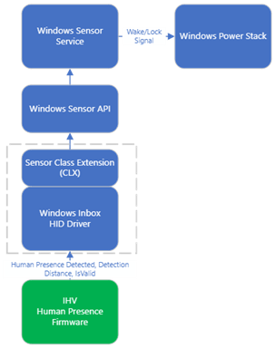
The diagrams below represent how the data from the sensor flows up the stack when the feature is functioning. External monitors will use the diagrams that are labeled as "HID".
| Driver Type / Sensor Capability | Distance-Capable HW (+/- 5cm) | Distance-Agnostic HW |
|---|---|---|
| HID: Human Interface Device | HID-based distance-capable data flow (recommended) | HID-based distance-agnostic data flow |
| CLX: Windows sensor class extension | CLX-based distance-capable data flow | CLX-based distance-agnostic data flow |
HID-based distance-capable data flow (recommended)
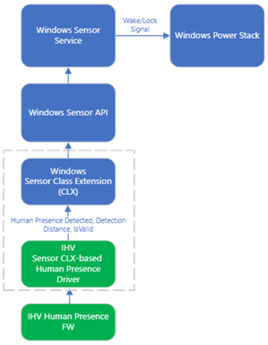
CLX-based distance-capable data flow
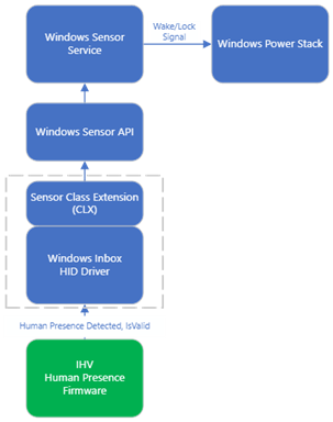
HID-based distance-agnostic data flow
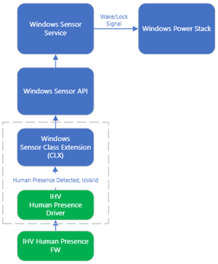
CLX-based distance-agnostic data flow
High level data flow
- User modifies the wake or lock settings via the settings UI and is communicated to the Windows sensor service.
- Windows sensor service starts the human presence sensor during normal operation or modern standby to monitor for wake and lock.
- Human presence sensor raises a new sample which contains human present, detection distance, and is valid.
- If the system is in modern standby and the new human presence sample reports a human within the configured detection range the Windows sensor service will send a wake signal to the Windows power stack. Conversely, if the system is in normal operation and a human is not reported or is outside of the configured detection range the Windows sensor service will send a timeout signal to the Windows power stack.
Human presence signals
Signals:
- User present signal – Occurs when the sensor reports a data sample with human present data field set to true. If system supports attention, then attention is set to engaged/true in this state.
- User present not engaged signal – Occurs in systems that support attention when the sensor reports a data sample with the human present data field set to true and then attention is set to unengaged or false.
- User not present signal – Occurs when the sensor reports a data sample with the human present data field set to false.
- User unknown signal – Signaled when human presence is unknown. This can occur if the sensor is spuriously removed or if the sensor has yet to report a valid sample.
Required HID descriptors and top-level collections
If implemented, using one of the HID-based architectures the following section describes the data fields for exposing presence information.
For additional information on exposing a device through HID see Sensors HID Usages.
Human presence – present (wake and lock)
| Usage ID | Comments |
|---|---|
| 0x04B1 HID_USAGE_SENSOR_DATA_BIOMETRIC_HUMAN_PRESENCE | Usage to expose a Boolean that indicates presence. Set this value to "1" to indicate human presence. Set this value to "0" to indicate no human presence. |
| 0x04B2 HID_USAGE_SENSOR_DATA_BIOMETRIC_HUMAN_PROXIMITY_RANGE | Used to expose distance values in the input report Default unit is in meters but the sample report descriptor in this document shows how the device can report millimeters. This will be made an optional field in a future Windows update. |
Note
The millimeter report must be accurate to within +/- 5000mm. The reported range may be continuous or in discrete increments of less than 5000mm (i.e. 2000mm, 7000mm,..).This will be made an optional field in a future Windows update.
Validation guide - Minimum requirements and testing: Windows Hardware Certification Program (WHCP)
The minimum test and requirements to certify your hardware as compatible is outlined in the Hardware Lab Kit (HLK) tests in the Windows Hardware Compatibility Program Specifications and Policies.