Required HID Top-Level Collections (touchpad-required-hid-top-level-collections)
This section discusses the required HID top-level collections that are used for precision touchpad reporting in Windows 10 and later operating systems.
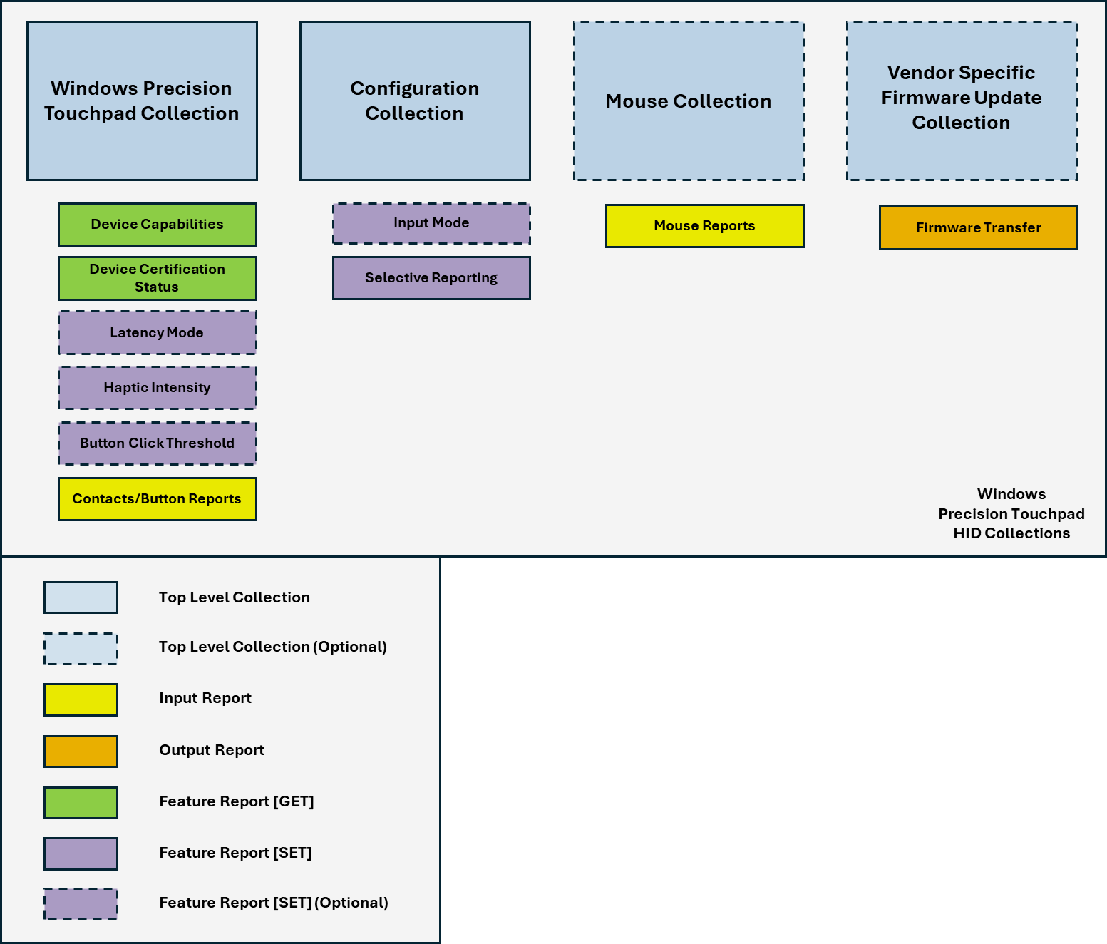
A Windows Precision Touchpad device should expose two mandatory top-level collections: A Windows Precision Touchpad collection, and a Configuration collection. Optional (but recommended) collections for firmware updates and basic mouse mode support may also be implemented.
The following diagram shows the HID collections for a Windows Precision Touchpad device.
A sample descriptor (showing top-level collections) is provided in the Sample Report Descriptors topic.
The following topics provide more details about the HID top-level collections.
In this section
| Topic | Description |
|---|---|
This topic discusses the mouse collection of a Windows Precision Touchpad device, and explains how the collection provides HID-compliant mouse reporting to the Windows host. |
|
This topic discusses the role played by the configuration collection of a Windows Precision Touchpad device, in Windows 10 and later operating systems. |
|
This topic discusses the top-level collection of a Windows Precision Touchpad, and explains how the collection provides HID-compliant touchpad reporting to the Windows host. |
|
This topic discusses the report level usages for buttons, within the context of the Windows Precision Touchpad Collection. |
|
A Windows Precision Touchpad device can use the HID protocol to provide a vendor-specific top-level collection for performing device firmware and vendor configuration updates. |