Note
Access to this page requires authorization. You can try signing in or changing directories.
Access to this page requires authorization. You can try changing directories.
On entry to modern standby, hardware components must be prepared to make the transition to low-power operation. After software components and apps have been prepared for low-power operation, hardware components, including their software device drivers, must be similarly prepared for low-power operation.
The remainder of this article explains how to prepare the devices outside and inside the System on a Chip (SoC) to operate in a low-power mode after the hardware platform enters standby.
Hardware transition to low-power mode
All devices outside the SoC and inside the SoC must enter a low-power mode in order to achieve long battery life during sleep. After a hardware platform enters sleep, the devices in the platform switch to low-power modes in an orderly process that starts with the devices outside the SoC.
First, all devices outside of the SoC or core silicon must enter a low-power mode. The power mode may be a clock-gated idle state—for example, placing an I²C-attached touch controller in a sleep mode. Or, the power mode may be a power-gated, 0-watt state called D3cold. A USB-attached web camera will often transition to D3cold during modern standby. For more information, see Supporting D3cold for USB Devices.
Each device class and connection bus has its own terminology and requirements for transitioning a device to the lowest power mode. However, it is critical that a system designer plan a low-power mode of operation for each device in the platform during modern standby. The battery life of the system and the ability to place the SoC itself in a low-power mode depend on correct power management of each device outside of the SoC itself.
Next, network and radio devices are placed in a low-power mode for sleep. During sleep, these devices often still have power applied to maintain connectivity and are required to wake the SoC if necessary. Communications and radio devices typically enter the D2/D3 low-power state, although the entry into each state is device class-specific and bus-specific.
After all devices outside of the SoC, including communications devices, have been powered down, the host controllers on the SoC will be turned off. Almost every SoC has USB, I²C, GPIO, SDIO, and UART host controllers. Each of these components on the SoC must be turned off in order for the SoC to enter a low-power mode.
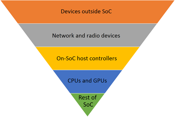
The process for preparing the hardware for low-power during sleep can be visualized as an upside-down pyramid, as shown in the following diagram. The lowest power is achieved when the whole SoC chip is powered down, but this can occur only after each set of devices above it in the pyramid has been powered down.
Powering down the devices outside the SoC
Each device outside of the SoC chip must enter a low-power mode for two key goals:
- Reduce the power consumption of the device.
- Allow the SoC itself to power down by allowing the on-SoC host controller, to which the device is connected, to power down.
The method to power down each device outside of the SoC varies by device class and attached bus.
Some devices outside of the SoC are placed in a 0-watt, no-power-consumed state called D3cold. Common devices for D3cold include cameras and sensors. The driver must save the register state of the device and then transition the device to the D3 power state. Power will be removed by the ACPI firmware by toggling a GPIO line or turning off a power rail from the power management IC (PMIC).
Some devices outside of the SoC are placed in a low-power idle mode in which register state is maintained, or the device might simply be clock-gated. For example, many touch controllers feature a clock-gated state that consumes less than 1 milliwatt of power. The typical advantages to using a clock-gated state are faster power-on time and lower cost by not having to connect the device to a switchable power rail.
Generally, every device outside of the SoC must be capable of entering a low-power mode that consumes less than 1 milliwatt of power. Devices that cannot achieve this power level with an internal clock-gated state should implement power-gating through D3cold.
Network and radio devices are the notable exception to the 1-milliwatt guideline. Network and radio devices might require more power to maintain a connection to the network or to listen to wireless devices. Some system designers refer to these power-state transitions as runtime D3 (RTD3).
Directed power management for PCIe devices
PCIe cards outside the SoC must enable a directed power management mechanism called Device-S4 in order to ensure that they can enter a low power mode. Without Device-S4, if a user plugs a device into a PCIe Root Port with user-accessible slots on a desktop Modern Standby system, and the driver for the device does not support runtime D3 (RTD3), the PCIe device may prevent the system from entering DRIPS. To avoid this problem, OEMs must opt in the Root Ports of the PCIe device to Device-S4. For Device-S4 to be engaged for a given PCIe device, the following requirements must be met:
- The parent PCIe Root Port for the device must be specified as a constraint for DRIPS.
- The parent PCIe Root Port must apply fundamental device reset for the all children downstream of the Root Port upon the Root Port's D0->D3 transition and deassert fundamental device reset to those children upon the D3->D0 transition. For more information about PCIe fundamental resets, please refer to Section 6.6.1 of the PCI Express Base Specification. The application of fundamental reset can be provided by supplemental ACPI mechanisms. For more information, please refer to this guide on PCI Power Management. To indicate that the platform honors this fundamental reset requirement, the firmware must define _DSD with support for GUID {FDF06FAD-F744-4451-BB64-ECD792215B10}. Without this, Directed DRIPS will not be triggered for devices under that PCIe Root Port. For more information, refer to the ACPI Device Specific Data (_DSD) for PCIe Root Ports.
- Power resources must be unique to a given PCIe Root Port, i.e. not shared with any other Root Port.
Please note that PCIe cards that require Compatibility Support Modules (CSM) will not work in Modern Standby systems. CSM is not supported in the BIOS on Modern Standby systems due to the UEFI Secure Boot requirement. For more information, please refer to the Windows Hardware Compatibility Program Specification.
For more information about power management for particular device classes, system designers are encouraged to review Device-specific power management for modern standby, as well as device-specific documentation on Microsoft Collaborate.
Powering down networking devices
Powering down the networking and radio devices is another key part of preparing the hardware for low-power operation during sleep. Networking and radio devices are different from other devices outside of the SoC because they must remain on with power applied to listen for interesting events and wake the SoC. For example, the Wi-Fi radio must be capable of listening for packets that match WoL patterns and waking the SoC when a matching packet is detected.
Windows transitions networking devices to the D2/D3 state during sleep if they are expected to wake the SoC. The Windows network stack will configure WoL patterns and protocol offloads before placing the device in the low-power D2/D3 state. All networking devices, including Wi-Fi, mobile broadband (MBB), and wired Ethernet, must be capable of entering the D2/D3 state during sleep. If a networking device is not required to wake the system, Windows will transition the device to the D3 state. The networking device can be placed in the D3 state if the user has enabled airplane mode or disabled the specific networking device.
Each device has a different physical method to wake the SoC from its lowest power mode. Networking devices on SDIO or UART are expected to signal a GPIO line to wake the SoC. Networking devices connected via USB or HSIC are expected to use in-band USB resume signaling to wake the SoC. Networking devices on PCI or PCIe buses are expected to use in-band PME signaling to wake the SoC.
In addition, a radio device, such as a Bluetooth or near-field communications (NFC) device, is expected to transition to the D2 state if the user has turned on the radio for this device. In the D2 state, a Bluetooth radio listens for input events from paired mice and keyboards. If an input event is detected, the Bluetooth radio toggles a GPIO line connected to the SoC, which causes the SoC to wake up from its low-power mode.
Each networking or radio device has its own implementation of powering down for modern standby. System designers are encouraged to read the device class-specific documents on the Microsoft Collaborate website.
Powering down on-SoC host controllers
After all devices outside of the SoC, including network and radio devices, have been powered down, the host controllers to which the devices are attached must power down. Common host controllers include USB, PCI, SDIO, GPIO, and I²C.
The driver for each host controller can power down the hardware only after every device connected to the host controller has powered down. A common example is the USB host controller. The USB host controller can power down only after all of the USB devices connected to it have entered a selective suspend state. If a USB host controller has a USB mouse and keyboard connected, the host controller can power down only after both the mouse and keyboard have powered down. If either the mouse or the keyboard stays powered on, the USB host controller also stays powered on.
All host controllers on the SoC must power down for sleep in order for the SoC itself to power down. This is why it is critical that every device perform device power management. The SoC itself can only power down when each host controller has powered down. The host controllers can power down only after all devices connected to them have powered down.
Powering down CPUs and GPUs
In terms of power management, CPUs and GPUs on the SoC chip are different from other devices. CPUs and GPUs power down as part of powering down the SoC itself and are able to be powered down whenever there is no software activity targeted to them.
Most software activity on the system will be stopped through the preparation stages detailed in Prepare software for modern standby. Microsoft Store apps will be paused as part of the PLM phase. Desktop applications will be paused as part of completing the DAM phase. The only CPU activities that remain after the platform enters the resiliency phase are idle operations of Windows itself. Similarly, there is little GPU activity because all apps have been paused and the screen is turned off.
Windows continually manages the power state of the CPUs on the system, even when the screen is on and the user is working with the PC. The same CPU power state management places the CPUs in a low-power mode during sleep. When all CPUs are in a low-power mode and all host controllers on the SoC have been powered down, the SoC itself can be powered down.
Powering down the SoC
When all the individual host controllers, CPUs, and GPUs on the SoC have been powered down, Windows will determine if it is safe to power down the entire SoC itself. The SoC vendor provides a power engine plug-in (PEP) to tell Windows when all of the state on the SoC has been saved so that the SoC is ready to enter a low-power mode. For Intel based SoCs, the PEP is provided inbox.
Each SoC vendor has a different implementation of a SoC-wide low-power state. These states are typically either clock-gated or power-gated states in which memory contents are preserved in self-refresh and the system can be awakened by a programmable timer and a small number of GPIO pins that consume very little power. Windows refers to the lowest SoC power state as deepest runtime idle platform state (DRIPS).
The DRIPS state always has the following characteristics:
- DRIPS is the lowest power consumption state for the SoC in which memory is preserved in a self-refresh mode.
- DRIPS allows the SoC to wake on events from networking, radio, and input devices.
- No CPU code is allowed to run during the DRIPS state.
- When the SoC is in the DRIPS state, the platform is consuming the least amount of power possible during sleep (with the exception of variances in power consumption caused by networking and radio devices).