Note
Access to this page requires authorization. You can try signing in or changing directories.
Access to this page requires authorization. You can try changing directories.
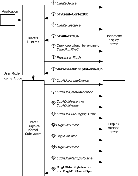
The following diagram shows the flow of WDDM operations that occur from when a rendering device is created to when the content is presented to the display. The information that follows the diagram describes the ordered sequence of the operation flow in more detail.
Creating a Rendering Device
After an application requests to create a rendering device:
1: The DirectX Graphics Kernel Subsystem (Dxgkrnl) calls the kernel-mode display miniport driver's (KMD) DxgkDdiCreateDevice function.
KMD initializes direct memory access (DMA) by returning a pointer to a filled DXGK_DEVICEINFO structure in the pInfo member of the DXGKARG_CREATEDEVICE structure.
2: If the call to DxgkDdiCreateDevice succeeds, the Direct3D runtime calls the user-mode display driver's (UMD) CreateDevice function.
3: In the CreateDevice call, UMD must explicitly call the runtime's pfnCreateContextCb function to create one or more GPU contexts, which are GPU threads of execution on the newly created device. The runtime returns information to UMD in the pCommandBuffer and CommandBufferSize members of the D3DDDICB_CREATECONTEXT structure to initialize the command buffer.
Creating Surfaces for a Device
After an application requests to create surfaces for the rendering device:
4: The Direct3D runtime calls UMD's CreateResource function.
5: CreateResource calls the runtime-supplied pfnAllocateCb function.
6: The runtime calls KMD's DxgkDdiCreateAllocation function, specifying the number and types of allocations to create. DxgkDdiCreateAllocation returns information about the allocations in an array of DXGK_ALLOCATIONINFO structures in the pAllocationInfo member of the DXGKARG_CREATEALLOCATION structure.
Submitting the Command Buffer to Kernel Mode
After an application requests to draw to a surface:
7: The Direct3D runtime calls the UMD function related to the drawing operation, for example, DrawPrimitive2.
8: The Direct3D runtime calls either the UMD's Present or Flush function to cause the command buffer to be submitted to kernel-mode. Note: UMD also submits the command buffer when the command buffer is full.
9: In response to Step 8, UMD calls one of the following runtime-supplied functions:
- The runtime's pfnPresentCb function if Present was called.
- The runtime's' pfnRenderCb function if Flush was called or the command buffer is full.
10: KMD's DxgkDdiPresent function is called if pfnPresentCb was called, or the DxgkDdiRender or DxgkDdiRenderKm function if pfnRenderCb was called. KMD validates the command buffer, writes to the DMA buffer in the hardware's format, and produces an allocation list that describes the surfaces used.
Submitting the DMA Buffer to Hardware
11: Dxgkrnl calls KMD's DxgkDdiBuildPagingBuffer function to create special purpose DMA buffers that move the allocations specified in the allocation list to and from GPU-accessible memory. These special DMA buffers are known as paging buffers. DxgkDdiBuildPagingBuffer isn't called for every frame.
12: Dxgkrnl calls KMD's DxgkDdiSubmitCommand function to queue the paging buffers to the GPU execution unit.
13: Dxgkrnl calls KMD's DxgkDdiPatch function to assign physical addresses to the resources in the DMA buffer.
14: Dxgkrnl calls KMD's DxgkDdiSubmitCommand function to queue the DMA buffer to the GPU execution unit. Each DMA buffer submitted to the GPU contains a fence identifier, which is a number. After the GPU finishes processing the DMA buffer, the GPU generates an interrupt.
15: KMD is notified of the interrupt in its DxgkDdiInterruptRoutine function. KMD should read the fence identifier of the completed DMA buffer from the GPU.
16: KMD should call DxgkCbNotifyInterrupt to notify Dxgkrnl that the DMA buffer completed. KMD should also call DxgkCbQueueDpc to queue a deferred procedure call (DPC).