Note
Access to this page requires authorization. You can try signing in or changing directories.
Access to this page requires authorization. You can try changing directories.
Because the MBIM 1.0 errata specification lacks a mechanism to change existing CIDs with new or modified payloads, Windows 10, version 1903 introduces MBIM 1.0 Extension 2.0 to extend the interface to support 5G.
Versioning scheme
Note
In this section, the term MBIMEx version refers to the MBIM Extensions release number.
The host learns a device's MBIMEx version through two ways:
- The MBIM EXTENDED FUNCTIONAL DESCRIPTOR.
- The optional MBM_CID_VERSION message, if the device supports it and declares support for it.
If these two are different, the higher version dictates the MBIMEx version for the duration that the device stays enumerated to the host. The higher MBIMEx version is referred to as the device's announced MBIMEx version. A device's announced MBIMEx version can be lower than its native MBIMEx version, which is the highest MBIMEx version that the device supports. Devices can learn the host's MBIMEx version explicitly only via the MBIM_CID_VERSION message.
In any release, the host always queries the device for supported services and CIDs using MBIM_CID_DEVICE_SERVICES at the beginning of the device initialization sequence.
If a device supports MBIM_CID_VERSION and advertises its support in the MBIM_CID_DEVICE_SERVICES query response, then a host that does not understand MBIM_CID_VERSION or has an MBIMEx version lower than 2.0 ignores it. Meanwhile, a host that does understand MBIM_CID_VERSION and has a native MBIMEx version of 2.0 or higher sends a MBIM_CID_VERSION message to the device with the host's native MBIMEx version, and the CID is the first CID that is sent to the device after receiving the MBIM_CID_DEVICE_SERVICES response.
If the first CID that the device receives from the host after it responds to the MBIM_CID_DEVICE_SERVICES query is MBIM_CID_VERSION, the device knows the host's MBIMEx version.
If the first CID that the device receives from the host after it responds to the MBIM_CID_DEVICE_SERVICES query is any other CID, then the device assumes that the host's native MBIMEx version is 1.0.
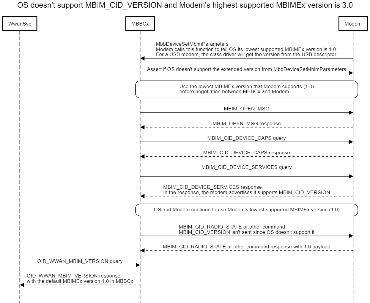
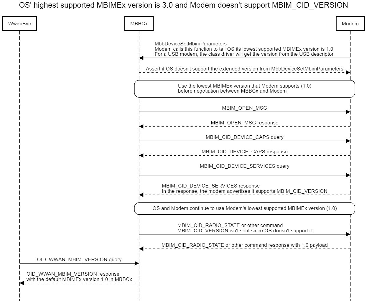
If the device doesn't support MBIM_CID_VERSION, it will not respond to the MBIM_CID_DEVICE_SERVICES query with MBIM_CID_VERSION. Therefore the host will not send a MBIM_CID_VERSION message and assumes that the device's native MBIMEx version is 1.0.
Feature-wise, a higher MBIMEx version is a superset of all lower MBIMEx versions. A host supports all devices with an announced MBIMEx version at or below the host's native MBIMEx version. If a device's announced MBIMEx version is higher than a host's native MBIMEx version, the host is not expected to support the device and the exact behavior of the host in this situation is undefined.
A device that intends to work with older hosts should initially advertise MBIMEx version 1.0 or the lowest host MBIMEx version with which the device is intended to work in an MBIM extended functional descriptor.
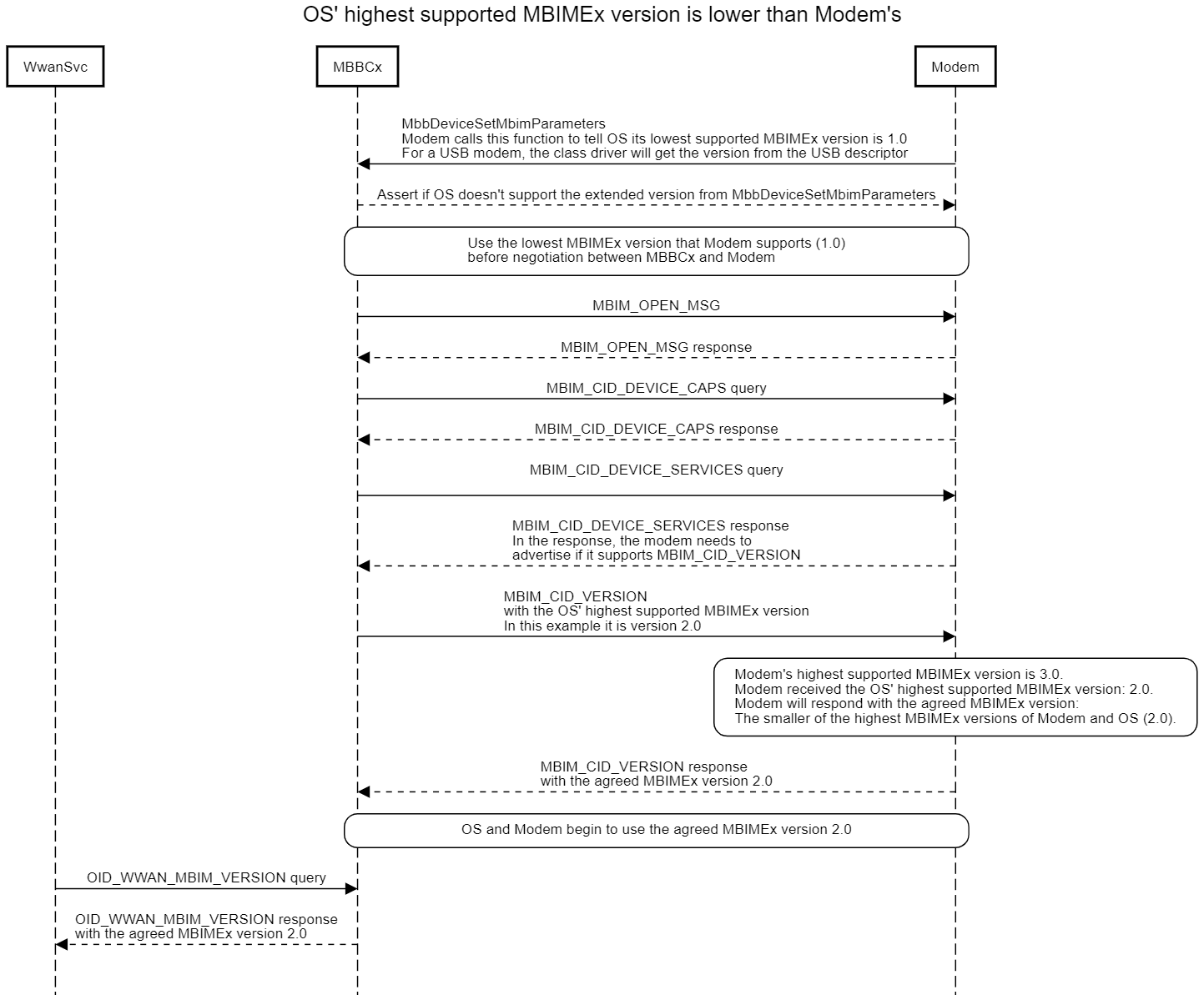
If the host sends MBIM_CID_VERSION with a higher MBIMEx version than the device initially advertised, then the device should indicate a higher MBIMEx version in the MBIM_CID_VERSION response up to the smaller of the host's native MBIMEx version and the device's native MBIMEx version.

Note
For example, a device supports MBIMEx version 2.0, but is intended to work with older versions of the OS that do not support MBIMEx 2.0. The device initially advertises MBIMEx version 1.0 in the USB descriptors and advertises support for the optional MBIM_CID_VERSION. When inserted into a host running Windows 10, version 1803, the host does not understand MBIM_CID_VERSION and does not send MBIM_CID_VERSION to the device. To the host, the device's MBIMEx version is 1.0. The host continues to send other CIDs in the initialization sequence. Upon receiving CIDs other than MBIM_CID_VERSION, the device knows that the host supports MBIMEx version 1.0. Both sides proceed to conform to MBIMEx version 1.0. Later, when the same device is inserted into a host running Windows 10, version 1903 with a native MBIMEx version of 2.0, the host sends MBIM_CID_VERSION to the device to inform it that the host's native MBIMEx version is 2.0. The device sends MBIM_CID_VERSION back in response with the device's announced MBIMEx version 2.0. From there, both sides proceed to conform to MBIMEx version 2.0.
The following table shows a compatibility matrix with three hypothetical hosts and three hypothetical devices, each with its native MBIMEx version stated. The devices advertise MBIMEx version 1.0 initially in the USB descriptor. The matrix shows how each of the devices behaves with each of the hosts.
| Device (below) / Host (right) | Windows 10, version 1809 or earlier (native MBIMEx version 1.0) | Windows 10, version 1903 and later (MBIMEx version 2.0) |
|---|---|---|
| 4G device Native MBIMEx version 1.0 |
Device initially advertises MBIMEx 1.0. No MBIM_CID_VERSION exchange. Compatible device and host. Works by default with MBIMEx version 1.0. | Device initially advertises MBIMEx 1.0. No MBIM_CID_VERSION exchange. The host works with the device using MBIMEx 1.0. |
| 5G NSA device Native MBIMEx version 2.0 |
Device initially advertises MBIMEx 1.0. No MBIM_CID_VERSION exchange. Device knows that the host has MBIMEx 1.0 and proceeds with MBIMEx 1.0. | Device initially advertises MBIMEx 1.0. Host sends MBIM_CID_VERSION to inform the device that the host supports MBIMEx 2.0. Device responds with MBIMEx 2.0. Both sides proceed with MBIMEx 2.0. |
The following table lists all existing CIDs that are modified in MBIMEx version 2.0, and their modified payloads. All unmentioned payloads in these CIDs and all other CIDs not mentioned in the table carry over from MBIMEx version 1.0 and remain unchanged.
| CID | Payload |
|---|---|
| MBIM_CID_REGISTER_STATE | MBIM_REGISTRATION_STATE_INFO_V2 |
| MBIM_CID_PACKET_SERVICE | MBIM_PACKET_SERVICE_INFO_V2 |
| MBIM_CID_SIGNAL_STATE | MBIM_SIGNAL_STATE_INFO_V2 |
MBIM service
| Service name | UUID | UUID value |
|---|---|---|
| Microsoft Basic IP Connectivity Extensions | UUID_BASIC_CONNECT_EXTENSIONS | 3D01DCC5-FEF5-4D05-9D3A-BEF7058E9AAF |
MBIM_CID_VERSION
For MBB drivers that support MBIM Microsoft extension 2.0 or above, MBIM_CID_VERSION is a mandatory command for exchanging MBIM version information between the host and the device. For in-market devices with drivers that do not recognize this CID, the host will assume and provide backward compatibility.
The host sends this command as a query if it is supported by the device. The query contains the MBIM release number and MBIM Extensions release number that the host currently supports.
On the device side, the device adjusts its announced MBIM release number and MBIM Extensions release number based on the rules defined in versioning scheme, then sends them in the response to the host.
This command is defined under the Basic Connect Extensions service.
| CID | Command code | UUID |
|---|---|---|
| MBIM_CID_VERSION | 15 | 3d01dcc5-fef5-4d05-0d3abef7058e9aaf |
Parameters
| Operation | Set | Query | Notification |
|---|---|---|---|
| Command | Not applicable | MBIM_VERSION_INFO | Not applicable |
| Response | Not applicable | MBIM_VERSION_INFO | Not applicable |
Query
Informs the device of the host's native MBIM release number and MBIM Extensions release number. The InformationBuffer contains the following MBIM_VERSION_INFO structure.
| Offset | Size | Field | Type | Description |
|---|---|---|---|---|
| 0 | 2 | bcdMBIMVersion | UINT16 | The MBIM release number of the sender in BCD, with an implied decimal point between bits 7 and 8. For example, 0x0100 == 1.00 == 1.0. This is a little-endian constant, so the bytes are 0x00, then 0x01. |
| 2 | 2 | bcdMBIMExtendedVersion | UINT16 | The MBIM Extensions release number of the sender in BCD, with an implied decimal point between bits 7 and 8. For example, 0x0100 == 1.00 == 1.0. This is a little-endian constant, so the bytes are 0x00, then 0x01. |
Set
Not applicable.
Response
The InformationBuffer in MBIM_COMMAND_DONE contains an MBIM_VERSION_INFO structure.
Unsolicited Events
Not applicable.
Status Codes
This CID only uses generic status codes defined in Section 9.4.5 of the MBIM specification revision 1.0.
MBIM_CID_MS_DEVICE_CAPS_V2
This CID is the same as defined on MB Multi-SIM operations, which itself is an extension of MBIM_CID_MS_DEVICE_CAPS as defined in Section 10.5.1 of the MBIM specification revision 1.0. For MBIM Extensions release 2.0, there are new data classes defined in the MBIM_DATA_CLASS table that enable the device to report its 5G capabilities. MBIMDataClass5G_NSA denotes that the device supports 5G Non-standalone (NSA), defined in 3GPP TS 37.340, and MBIMDataClass5G_SA denotes that the device supports 5G Standalone (SA), also defined in 3GPP TS 37.340.
If the device supports both new data classes, then both bits shall be set.
MBIM_DATA_CLASS
| Types | Mask |
|---|---|
| MBIMDataClassNone | 0h |
| MBIMDataClassGPRS | 1h |
| MBIMDataClassEDGE | 2h |
| MBIMDataClassUMTS | 4h |
| MBIMDataClassHSDPA | 8h |
| MBIMDataClassHSUPA | 10h |
| MBIMDataClassLTE | 20h |
| MBIMDataClass5G_NSA | 40h |
| MBIMDataClass5G_SA | 80h |
| Reserved | 100h-8000h |
| MBIMDataClass1XRTT | 10000h |
| MBIMDataClass1XEVDO | 20000h |
| MBIMDataClass1XEVDORevA | 40000h |
| MBIMDataClass1XEVDV | 80000h |
| MBIMDataClass3XRTT | 100000h |
| MBIMDataClass1XEVDORevB | 200000h |
| MBIMDataClassUMB | 400000h |
| Reserved | 800000-40000000h |
| MBIMDataClassCustom | 80000000h |
MBIM_CID_REGISTER_STATE
This command is an extension for the MBIM_CID_REGISTER_STATE CID already defined in the MBIM specification revision 1.0. This extension adds a new member called PreferredDataClasses for the response structure.
Parameters
| Operation | Set | Query | Notification |
|---|---|---|---|
| Command | MBIM_SET_REGISTRATION_STATE | Empty | Not applicable |
| Response | MBIM_REGISTRATION_STATE_INFO_V2 | MBIM_REGISTRATION_STATE_INFO_V2 | MBIM_REGISTRATION_STATE_INFO_V2 |
Query
The InformationBuffer is null and the InformationBufferLength is zero.
Set
Sets the registration state. The information is the same as described in the MBIM specification revision 1.0.
Response
The InformationBuffer in MBIM_COMMAND_DONE contains the following MBIM_REGISTRATION_STATE_INFO_V2 structure. Compared with the MBIM_REGISTRATION_STATE_INFO structure defined in Section 10.5.10.6 of the MBIM specification revision 1.0, the following structure has a new PreferredDataClasses field. Unless stated here, field descriptions in table 10-55 of the MBIM specification revision 1.0 apply to this structure.
MBIM_REGISTRATION_STATE_INFO_V2
| Offset | Size | Field | Type | Description |
|---|---|---|---|---|
| 0 | 4 | NwError | UINT32 | A network-specific error. Table 10-44 in the MBIM specification revision 1.0 documents the cause codes for NwError. |
| 4 | 4 | RegisterState | MBIM_REGISTER_STATE | See Table 10-46 in the MBIM specification revision 1.0. |
| 8 | 4 | RegisterMode | MBIM_REGISTER_MODE | See Table 10-47 in the MBIM specification revision 1.0. |
| 12 | 4 | AvailableDataClass | UINT32 | A bitmap of the values in MBIM_DATA_CLASS that represents the supported data classes on the registered network, for the cell in which the device is registered. This value is set to MBIMDataClassNone if the RegisterState is not MBIMRegisterStateHome, MBIMRegisterStateRoaming, or MBIMRegisterStatePartner. |
| 16 | 4 | CurrentCellularClass | MBIM_CELLULAR_CLASS | Indicates the current cellular class in use for a multi-mode function. See Table 10-8 in the MBIM specification revision 1.0 for more information. For a single-mode function, this is the same as the cellular class reported in MBIM_CID_DEVICE_CAPS. For multi-mode functions, a transition from CDMA to GSM or vice versa is indicated with an updated CurrentCellularClass. |
| 20 | 4 | ProviderIdOffset | OFFSET | The offset in bytes, calculated from the beginning of this structure, to a numeric (0-9) string called ProviderId that represents the network provider identity. For GSM-based networks, this string is a concatenation of a three-digit Mobile Country Code (MCC) and a two- or three-digit Mobile Network Code (MNC). GSM-based carriers might have more than one MNC, and hence more than one ProviderId. For CDMA-based networks, this string is a five-digit System ID (SID). Generally, a CDMA-based carrier has more than one SID. Typically, a carrier has one SID for each market that is usually divided geographically within a nation by regulations, such as Metropolitan Statistical Areas (MSA) in the United States. CDMA-based devices must specify MBIM_CDMA_DEFAULT_PROVIDER_ID if this information is not available. When processing a query request and the registration state is in automatic register mode, this member contains the provider ID with which the device is currently associated (if applicable). When the registration state is in manual register mode, this member contains the provider ID to which the device is requested to register (even if the provider is unavailable). When processing a set request and the registration state is in manual mode, this contains the provider ID selected by the host with which to register the device. When the registration state is in automatic register mode, this parameter is ignored. CDMA 1xRTT providers must be set to MBIM_CDMA_DEFAULT_PROVIDER_ID if the provider ID is not available. |
| 24 | 4 | ProviderIdSize | SIZE(0..12) | The size, in bytes, for ProviderId. |
| 28 | 4 | ProviderNameOffset | OFFSET | The offset in bytes, calculated from the beginning of this structure, to a string called ProviderName that represents the network provider's name. This member is limited to, at most, MBIM_PROVIDERNAME_LEN characters. For GSM-based networks, if the Preferred Presentation of Country Initials and Mobile Network Name (PCCI&N) is longer than twenty characters, the device should abbreviate the network name. This member is ignored when the host sets the preferred provider list. Devices should specify a NULL string for devices that do not have this information. |
| 32 | 4 | ProviderNameSize | SIZE(0..40) | The size, in bytes, for ProviderName. |
| 36 | 4 | RoamingTextOffset | OFFSET | The offset in bytes, calculated from the beginning of this structure, to a string called RoamingText to inform a user that the device is roaming. This member is limited to, at most, 63 characters. This text should provide additional information to the user when the registration state is either MBIMRegisterStatePartner or MBIMRegisterStateRoaming. This member is optional. |
| 40 | 4 | RoamingTextSize | SIZE(0..126) | The size, in bytes, for RoamingText. |
| 44 | 4 | RegistrationFlag | MBIM_REGISTRATION_FLAGS | Flags set per Table 10-48 in the MBIM specification revision 1.0. |
| 48 | 4 | PreferredDataClass | UINT32 | A bitmap of the values in MBIM_DATA_CLASS that represent the enabled data classes on the device. The device can only operate using the data classes that are enabled. |
| Dynamic | 4 | DataBuffer | DATABUFFER | The data buffer that contains ProviderId, ProviderName, and RoamingText. |
Unsolicited Events
Notifications contain an MBIM_REGISTRATION_STATE_INFO_V2 structure.
Status Codes
This CID only uses generic status codes defined in Section 9.4.5 of the MBIM specification revision 1.0.
MBIM_CID_PACKET_SERVICE
This command is an extension for the existing MBIM_CID_PACKET_SERVICE defined in the MBIM specification revision 1.0.
This extension adds a new member called FrequencyRange for the response structure and renamed the HighestAvailableDataClass member to CurrentDataClass to clarify its purpose.
The CurrentDataClass indicates the Radio Access Technology (RAT) with which the device is currently registered. It contains a single value from MBIM_DATA_CLASS.
The FrequencyRange indicates the frequency range that the device is currently using. This is valid only if the CurrentDataClass field indicates that the MBIMDataClass5G_NSA or MBIMDataClass5G_SA bit is set.
Parameters
| Operation | Set | Query | Notification |
|---|---|---|---|
| Command | MBIM_SET_PACKET_SERVICE | Empty | Not applicable |
| Response | MBIM_PACKET_SERVICE_INFO_V2 | MBIM_PACKET_SERVICE_INFO_V2 | MBIM_PACKET_SERVICE_INFO_V2 |
Query
The InformationBuffer is null and the InformationBufferLength is zero.
Set
Information for set commands is described in the MBIM specification revision 1.0.
Response
The InformationBuffer in MBIM_COMMAND_DONE contains an MBIM_PACKET_SERVICE_INFO_V2 structure. Compared with the MBIM_PACKET_SERVICE_INFO structure defined in Section 10.5.10.6 of the MBIM specification revision 1.0, this new structure has the CurrentDataClass and FrequencyRange fields. Unless stated here, the field descriptions in Table 10-55 of the MBIM specification revision 1.0 apply here.
MBIM_PACKET_SERVICE_INFO_V2
| Offset | Size | Field | Type | Description |
|---|---|---|---|---|
| 0 | 4 | NwError | UINT32 | A network-specific error. Table 10-44 in the MBIM specification revision 1.0 documents the cause codes for NwError. |
| 4 | 4 | PacketServiceState | MBIM_PACKET_SERVICE_STATE | See Table 10-53 in the MBIM specification revision 1.0. |
| 8 | 4 | CurrentDataClass | MBIM_DATA_CLASS | The current data class in the current cell, specified according to MBIM_DATA_CLASS. Functions must set this member to MBIMDataClassNone if the function is not in the attached packet service state. Except for HSPA (in other words, HSUPA and HSDPA) and 5G DC, the function sets this member to a single MBIM_DATA_CLASS value. For HSPA data services, functions specify a bitwise OR of MBIMDataClass HSDPA and MBIMDataClassHSUPA. For cells that support HSDPA but not HSUPA, only HSDPA is indicated (implying UMTS data class for uplink data). Whenever the current data class changes, functions send a notification indicating the new value of CurrentDataClass. |
| 12 | 8 | UplinkSpeed | UINT64 | Contains the uplink bit rate, in bits per second. |
| 20 | 8 | DownlinkSpeed | UINT64 | Contains the downlink bit rate, in bits per second. |
| 38 | 4 | FrequencyRange | MBIM_FREQUENCY_RANGE | A bitmask of values in MBIM_FREQUENCY_RANGE that represents the frequency ranges that the device is currently using. This is only valid if the CurrentDataClass is either MBIMDataClass5G_NSA or MBIMDataClass5G_SA. |
MBIM_FREQUENCY_RANGE
The following enumeration is used as a value in the preceding MBIM_PACKET_SERVICE_INFO_V2 structure.
| Type | Value | Description |
|---|---|---|
| MBIMFrequencyRangeUnknown | 0 | If the system type is not 5G. |
| MBIMFrequencyRange1 | 1 | Frequency range 1 (FR1) in 3GPP TS 38.101-1 (Sub-6G). |
| MBIMFrequencyRange2 | 2 | FR2 in 3GPP TS 38.101-2 (mmWave). |
| MBIMFrequencyRange1AndRange2 | 3 | If both FR1 and FR2 carriers are connected. |
Unsolicited Events
Notifications contain an MBIM_PACKET_SERVICE_INFO_V2 structure.
Status Codes
This CID only uses generic status codes defined in Section 9.4.5 of the MBIM specification revision 1.0.
MBIM_CID_SIGNAL_STATE
This CID is an extension to MBIM_CID_SIGNAL_STATE, introducing RSRP and SNR for signal state criteria. This new extension is only valid if the device indicates support of MBIM Extensions version 2.0. This extension is mandatory if the modem supports MBIMDataClass5G_(N)SA data classes.
The RSRP and SNR fields are only valid if the corresponding SystemType is either MGBIMDataClassLTE or MBIMDataClass5G_(N)SA. IF the modem reports RSRP and/or SNR, then the RSSI field shall be set to a value of 99.
If the corresponding SystemType is MBIMDataClass5G_(N)SA, the RSRP field is mandatory and the SNR field is optional. If the corresponding SystemType is MBIMDataClassLTE, the RSRP and SNR fields are optional and the RSSI field can be used instead. In this case, the RSRP and SNR fields can be omitted by setting a zero (0) value for both RsrpSnrOffset and RsrpSnrSize members.
Parameters
| Operation | Set | Query | Notification |
|---|---|---|---|
| Command | MBIM_SET_SIGNAL_STATE | Empty | Not applicable |
| Response | MBIM_SIGNAL_STATE_INFO_V2 | MBIM_SIGNAL_STATE_INFO_V2 | MBIM_SIGNAL_STATE_INFO_V2 |
Query
The InformationBuffer is null and the InformationBufferLength is zero.
Set
Information for set commands is described in the MBIM specification revision 1.0.
Response
The InformationBuffer in MBIM_COMMAND_DONE contains the following MBIM_SIGNAL_STATE_INFO_V2 structure.
MBIM_SIGNAL_STATE_INFO_V2
| Offset | Size | Field | Type | Description |
|---|---|---|---|---|
| 0 | 4 | Rssi | UINT32 | See Table 10.58 in the MBIM specification revision 1.0. |
| 4 | 4 | ErrorRate | UINT32 | See Table 10.58 in the MBIM specification revision 1.0. |
| 8 | 4 | SignalStrengthInterval | UINT32 | The reporting interval, in seconds. |
| 12 | 4 | RssiThreshold | UINT32 | The difference in RSSI coded values that triggers a report. Use 0xFFFFFFFF if this does not matter. |
| 16 | 4 | ErrorRateThreshold | UINT32 | The difference in ErrorRate coded values that trigger a report. Use 0xFFFFFFFF if this does not matter. |
| 20 | 4 | RsrpSnrOffset | OFFSET | The offset in bytes, calculated from the beginning of this structure, to the buffer containing RSRP and SNR signaling info. This member can be NULL when no RSRP and SNR signaling info is available. |
| 24 | 4 | RsrpSnrSize | SIZE | The size, in bytes, of the buffer containing the RSRP and SNR signaling info in the format of a MBIM_RSRP_SNR_INFO structure. |
| 4 | DataBuffer | DATABUFFER | An MBIM_RSRP_SNR structure. |
MBIM_RSRP_SNR
The following MBIM_RSRP_SNR structure is used in the DataBuffer of an MBIM_SIGNAL_STATE_INFO_V2 structure.
| Offset | Size | Field | Type | Description |
|---|---|---|---|---|
| 0 | 4 | ElementCount | UINT32 | The count of RSRP_SNR entries that follow this element. |
| 4 | 4 | DataBuffer | DATABUFFER | An array of RSRP_SNR records, each specified as an MBIM_RSRP_SNR_INFO structure. |
MBIM_RSRP_SNR_INFO
An array of the following MBIM_RSRP_SNR_INFO structures is used in the DataBuffer of an MBIM_RSRP_SNR structure.
| Offset | Size> | Field | Type | Description | ||||||||||||||||||||||
|---|---|---|---|---|---|---|---|---|---|---|---|---|---|---|---|---|---|---|---|---|---|---|---|---|---|---|
| 0 | 4 | RSRP | UINT32 |
|
||||||||||||||||||||||
| 4 | 4 | SNR | UINT32 |
|
||||||||||||||||||||||
| 8 | 4 | RSRPThreshold | UINT32 | Defines the threshold between the old (cached) RSRP value and the newly calculated RSRP value. If the absolute difference is larger than the threshold value, the device triggers an unsolicited event. The unit is 1 dBm. If set to zero, use the default behavior in the device function. If set to 0xFFFFFFFF, don't use this to trigger the event. If the given threshold value is not supported by the device, it returns the max threshold value that it supports. | ||||||||||||||||||||||
| 12 | 4 | SNRThreshold | UINT32 | Defines the threshold between the old (cached) SNR value and the newly calculated SNR value. If the absolute difference is larger than the threshold value, the device triggers an unsolicited event. The unit is 1 dB. If set to zero, use the default behavior in the device function. If set to 0xFFFFFFFF, don't use this to trigger the event. If the given threshold is not supported by the device, it returns the max threshold value that it supports. | ||||||||||||||||||||||
| 16 | 4 | SystemType | MBIM_DATA_CLASS | Indicates the system type for which signal state information is valid. This member is a bitmask of one type as defined in MBIM_DATA_CLASS. |
Unsolicited Events
Notifications contain an MBIM_SIGNAL_STATE_INFO_V2 structure.
Status Codes
This CID only uses generic status codes defined in Section 9.4.5 of the MBIM specification revision 1.0.
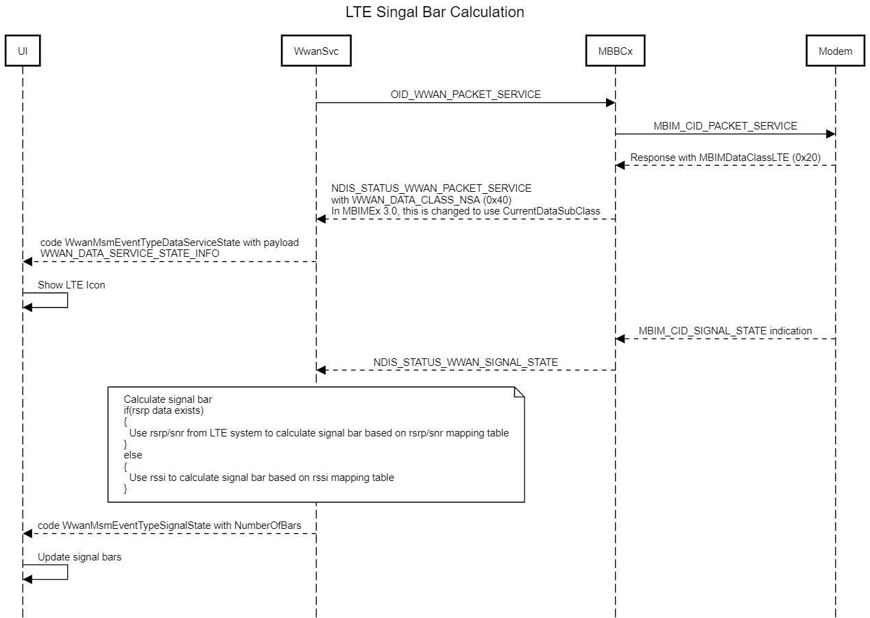
LTE signal bar calculation
The OS shall process the registry settings for signal strength calculations in the following order:
Dataclass is CDMA (or its variant) or TDSCDMA
- If a legacy signal bar mapping table exists under “per_iccid”, use this setting.
- Else, if a legacy signal bar mapping table exists under “per_device”, use this setting.
- Else, use the default signal bar mapping table in code.
Dataclass is GSM or WCDMA
- If a GSM or WCDMA technology specific signal bar mapping table exists under “per_iccid”, use this setting.
- Else, if a GSM or WCDMA technology specific signal bar mapping table exists under “per_device”, use this setting.
- Else, if a legacy signal bar mapping table exists under “per_iccid”, use this setting.
- Else, if a legacy signal bar mapping table exists under “per_device”, use this setting.
- Else, use the default signal bar mapping table in code.
- RSSI >= 17; 5 bars
- RSSI >= 12; 4 bars
- RSSI >= 7; 3 bars
- RSSI >= 4; 2 bars
- RSSI >= 2; 1 bars
- else; 0 bars
Dataclass is LTE and RSRP is reported by the modem
- If a LTE technology specific signal bar mapping table for RSRP exists under “per_iccid”, use this setting.
- Else, if a LTE technology specific signal bar mapping table for RSRP exists under “per_device”, use this setting.
- Else, use the default LTE RSRP signal bar mapping table in code.
Note
If EnableLTESnrReporting is enabled but there is no SNR table for LTE or SNR reporting by the modem, only RSRP is used. Otherwise, the better of RSRP or SNR is converted to signal bars.
Dataclass is LTE and RSSI is reported by the modem
- If a LTE technology specific signal bar mapping table exists under “per_iccid”, use this setting.
- Else, if a LTE technology specific signal bar mapping table exists under “per_device”, use this setting.
- Else, if a legacy signal bar mapping table exists under “per_iccid”, use this setting.
- Else, if a legacy signal bar mapping table exists under “per_device”, use this setting.
- Else, use the default signal bar mapping table in code.
Dataclass is NR
- If a NR technology specific signal bar mapping table for RSRP exists under “per_iccid”, use this setting.
- Else, if a NR technology specific signal bar mapping table for RSRP exists under “per_device”, use this setting.
- Else, use the default NR RSRP signal bar mapping table in code.
Note
If EnableNRSnrReporting is enabled, but no there is no SNR table for NR or SNR reporting by the modem, only RSRP is used. Otherwise, the better of RSRP or SNR is converted to signal bars.
Dataclass is NSA
- If EnableLTEReportingOnNSA is not set or is set to 0:
- Follow the Dataclass NR flow.
- If EnableLTEReportingOnNSA is set to 1:
- Follow the Dataclass LTE flows (RSRP or RSSI).
- If EnableLTEReportingOnNSA is set to 2:
- If FrequencyRange is FR1, follow the Dataclass LTE flows (RSRP or RSSI).
- If FrequencyRange is <> FR1, follow the Dataclass NR flow.
- If EnableLTEReportingOnNSA is set to 3:
- If FrequencyRange is FR2, follow the Dataclass LTE flows (RSRP or RSSI).
- If FrequencyRange is <> FR2, follow the Dataclass NR flow.
- If EnableLTEReportingOnNSA is set to 4:
- Calculate signal bar using the LTE and NR flows.
- Select the strongest.
Note
If the LTE signal is not reported by the modem in 1-5, the NR signal is used. If the NR signal is not used, the LTE signal is applied.
COSA customizations for SignalBar calculation
EnableLTEReportingOnNSA:
0 = "Use 5G signal"
1 = "Use LTE signal"
2 = "Use LTE signal if camped on 5G frequency range 1"
3 = "Use LTE signal if camped on 5G frequency range 2"
4 = "Use the strongest signal of LTE and 5G"
EnableNRSnrReporting:
0 = "Use only RSRP"
1 = "Use both RSRP and SNR"
EnableLTESnrReporting:
0 = "Use only RSRP"
1 = "Use both RSRP and SNR"
Cellular/PerDevice/SignalBarMappingTable/SignalForBars/<SignalBar>
Modify the minimum signal strength value corresponding to the number of bars to be shown. Technology specific settings take precedence. Each number of bars needs to have a valid signal strength mapping for this setting to take effect.
Cellular/PerDevice/SignalBarMappingTable/SignalForBars/GERAN/<SignalBar>
Modify the minimum signal strength value corresponding to the number of bars to be shown when device is camped on GSM. Each number of bars needs to have a valid signal strength mapping for this setting to take effect.
Cellular/PerDevice/SignalBarMappingTable/SignalForBars/WCDMA/<SignalBar>
Modify the minimum signal strength value corresponding to the number of bars to be shown when device is camped on WCDMA. Each number of bars needs to have a valid signal strength mapping for this setting to take effect.
Cellular/PerDevice/SignalBarMappingTable/SignalForBars/LTE/<SignalBar>
Modify the minimum signal strength value corresponding to the number of bars to be shown when device is camped on LTE. Each number of bars needs to have a valid signal strength mapping for this setting to take effect.
Cellular/PerDevice/SignalBarMappingTable/SignalForBars/LTERSRP/<SignalBar>
Modify the minimum signal strength value corresponding to the number of bars to be shown, when device is camped on LTE. Each number of bars needs to have a valid signal strength mapping for this setting to take effect.
Cellular/PerDevice/SignalBarMappingTable/SignalForBars/LTERSSNR/<SignalBar>
Modify the minimum signal strength value corresponding to the number of bars to be shown when device is camped on LTE. Used when EnableLTESnrReporting is set to 1. Each number of bars needs to have a valid signal strength mapping for this setting to take effect.
Cellular/PerDevice/SignalBarMappingTable/SignalForBars/NRRSRP/<SignalBar>
Modify the minimum signal strength value corresponding to the number of bars to be shown when device is camped on 5G. Each number of bars needs to have a valid signal strength mapping for this setting to take effect.
Cellular/PerDevice/SignalBarMappingTable/SignalForBars/NRRSSNR/<SignalBar>
Modify the minimum signal strength value corresponding to the number of bars to be shown when device is camped on 5G. Used when EnableNRSnrReporting is set to 1. Each number of bars needs to have a valid signal strength mapping for this setting to take effect.
<SignalBar> can be 1-5 values.
If the OEM/MO fails to properly configure the mapping table for RSSI or it’s incomplete, use the default mapping:
| RSSI | Bars Displayed |
|---|---|
| [0,1] | 0 |
| [2,3] | 1 |
| [4,6] | 2 |
| [7,11] | 3 |
| [12,16] | 4 |
| [17,31] | 5 |
If the OEM/MO fails to properly configure the mapping table for RSRP or it’s incomplete, use the default mapping:
| RSRP | Bars Displayed |
|---|---|
| [0,16] | 0 |
| [17,41] | 1 |
| [42,51] | 2 |
| [52,61] | 3 |
| [62,71] | 4 |
| [72,126] | 5 |
If the OEM/MO fails to properly configure the mapping table for SNR or it’s incomplete, use the default mapping:
| SNR | Bars Displayed |
|---|---|
| [0,18] | 0 |
| [19,38] | 1 |
| [39,46] | 2 |
| [47,53] | 3 |
| [54,72] | 4 |
| [73,127] | 5 |