Note
Access to this page requires authorization. You can try signing in or changing directories.
Access to this page requires authorization. You can try changing directories.
The video capture stack in Windows supports a user-mode extension in the form of DMFT. This is a per-device extension component that IHVs supply, and the capture pipeline inserts as the first transform, post-capture. The DMFT receives post-processed frames from the device. Further post processing operations on the frames can be done inside the DMFT. The DMFT can receive frames from all the streams of the device and it can expose any number of output streams as per the requirement.
This article outlines the design of a device-wide extension running in user mode that can be used to perform post-processing common to all streams.
Terminology
| Term | Description |
|---|---|
| KS | Kernel Streaming driver |
| AVStream | Audio Video Streaming driver model |
| Filter | Object that represents a device instance |
| Device MFT | User-mode capture driver extension supplied by IHVs |
| Devproxy | MF <-> AVStream marshaler |
| DTM | Device Transform Manager that manages devproxy and Device MFT. Represents the device in MF pipeline. |
Design goals
Device filter-wide user-mode extension that has same lifetime as the Device Filter
Supports any number of inputs coming from the device
Supports any number of outputs (current requirement is three streams: preview, record, and photo)
Routes all device controls to Device MFT (which optionally handles or passes it to the device)
Parallel post processing of captured stream
Allow 3A processing independent of frame rate
Allow metadata from one stream to be shared among other streams
Access to GPU resources
Access to MF MMCSS Work Queues
Access to MF Allocator
Simple interface (similar to MFT)
Flexible internal architecture for IHV/OEM extensibility
Design constraints
No change in the Capture API surface
Complete backward compatibility. For example, no regressions while working with legacy apps and scenarios.
Capture stack architecture
This article describes support for a filter-wide user-mode extension to the capture driver. This component has access to MF APIs, thread pools, GPU, and ISP resources. The filter wide extension provides the flexibility of having any number of streams between itself and device Ks filter. This flexibility enables seamless out of band communication between the user-mode extension and driver that can be used for dedicated metadata and 3A processing streams.
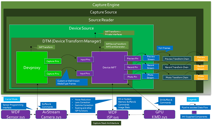
Device Transform Manager (DTM)
The capture stack introduces a new system-provided component, the Device Transform Manager (DTM). This resides inside DeviceSource and manages Devproxy MFT and Device MFT. DTM does the MediaType negotiation, sample propagation, and all MFT event handling. It also exposes the IMFTransform interface to DeviceSource and other necessary private interfaces that DeviceSource needs to manage device streams. This component abstracts Devproxy and Device MFT from the pipeline. The pipeline just sees the DTM as the device and the streams out of DTM as the device streams.
Devproxy
Devproxy is an async MFT that marshals the commands and video frames between the AVStream camera driver and Media Foundation. This is provided by Windows and supports n number of outputs from the camera driver. Also, this owns the allocators for all the pins exposed by the device.
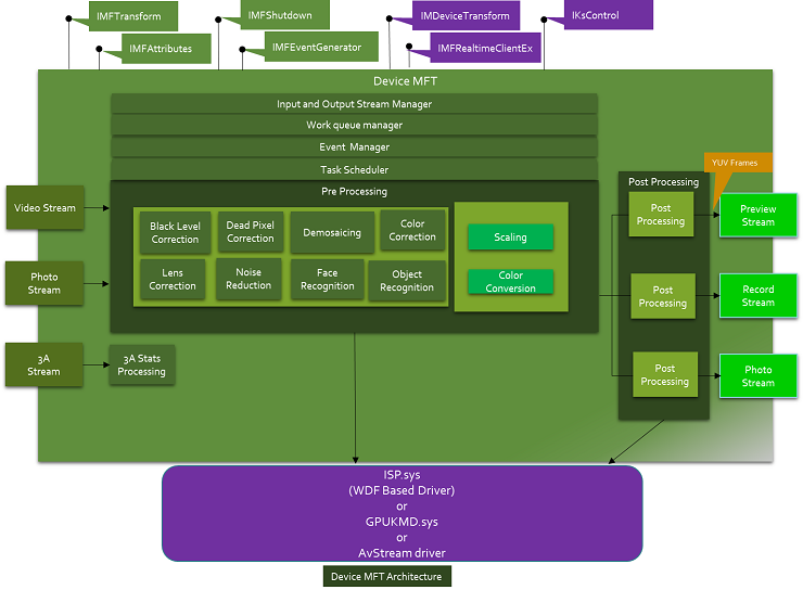
Device MFT
Device MFT is a user-mode extension to the capture driver. It's an m x n async MFT. It's installed on the system with the capture driver and is provided by the capture driver vendor.
The number of input streams of Device MFT must be same as the number of Ks pins exposed by the device. The mediatypes supported by Device MFT's input streams must be same as the mediatypes exposed by the KS pins.
The number of output streams exposed by Device MFT are the streams seen by DeviceSource and capture stack, capture API, and applications and can be one, two, or three stream. The input and output stream counts of Device MFT don't need to be the same. Also, input and output streams don't need to have the same mediatypes, and typically has different mediatypes. The number of mediatypes need not match either.
The first Ks Pin represented in user mode by Devproxy's output stream gets associated with the first input stream of Device MFT, the second Ks Pin represented in user mode by Devproxy's output stream with the second input stream of Device MFT, and so on.
Device MFT is given a pointer to Devproxy, DX device, and MF WorkQueue ID. Frames coming out of the device are fed directly into the corresponding Device MFT's input as MF Samples. With all these, Device MFT can post process the captured samples and serve samples to the preview, record, and photo pins.
All the commands and controls going to the device are rerouted to Device MFT. Device MFT handles the controls or passes them on to the driver through Devproxy. This streamlines command handling by the capture driver stack.
Functional overview
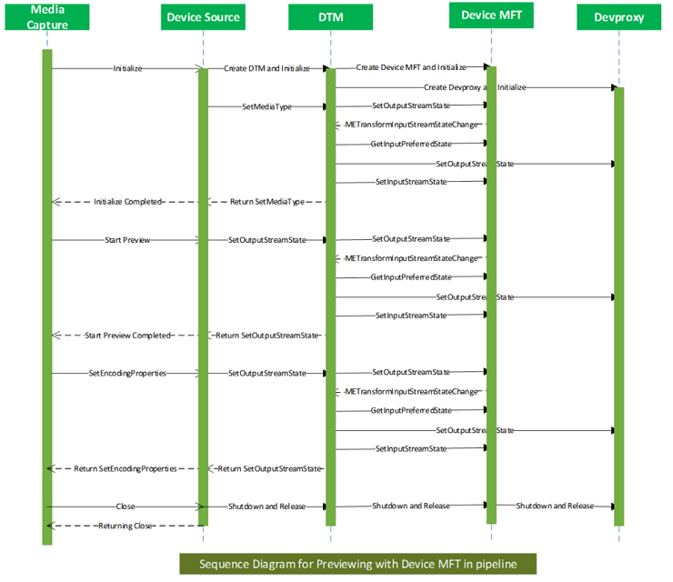
On initialization of the capture pipeline, if there's a Device MFT for the device, DeviceSource instantiates DTM. It passes an instance of Devproxy that represents the device to the DTM's initialization routine. DTM cocreates Device MFT and performs basic validations, for example, verifies the number of output pins of Devproxy is same as the number of input pins of Device MFT, support for mandatory interfaces, and so on.
DeviceSource queries DTM to obtain the supported output mediatypes. DTM gets this from Device MFT's output pins. DeviceSource exposes the Presentation Descriptor and Stream Descriptor based on this information to the capture pipeline.
SourceReader uses the exposed mediatypes of the DeviceSource and sets the default mediatypes on each stream. In turn, DeviceSource sets the default mediatypes on the output streams of the DTM. DTM sets the mediatype on the output stream of the Device MFT using the SetOutputStreamState method.
When SetOutputStreamState is called, Device MFT posts a message to DTM to change its input stream's mediatype based on the selected output mediatype and waits. In response to this message, DTM queries the preferred input mediatype for the input stream of the Device MFT using GetPreferredInputStreamState. This sets the mediatype on the corresponding output stream of Devproxy. If that succeeds, then DTM sets that same mediatype on to the Device MFT's input stream using SetInputStreamState. After receiving this call, Device MFT completes SetOutputStreamState.
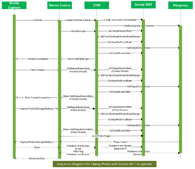
CaptureEngine selects individual streams by enabling specific streams on DeviceSource. This is propagated to Device MFT by DTM through a SetOutputStreamState call. Device MFT places the specific output streams in the requested state. As mentioned above, Device MFT also notifies DTM about the necessary input streams that need to be enabled. This results in DTM propagating the stream selection to Devproxy. At the end of this process, all necessary streams, in Devproxy and Device MFT, are ready to stream.
SourceReader starts the DeviceSource when CaptureEngine calls ReadSample. In turn, DeviceSource starts the DTM by sending MFT_MESSAGE_NOTIFY_BEGIN_STREAMING and MFT_MESSAGE_NOTIFY_START_OF_STREAM messages indicating the start of the pipeline. DTM starts Devproxy and Device MFT by propagating MFT_MESSAGE_NOTIFY_BEGIN_STREAMING and MFT_MESSAGE_NOTIFY_START_OF_STREAM messages.
Note
Allocate the necessary resources on start streaming instead of Device MFT initialize.
DTM calls SetOutputStreamState on Device MFT's outputs with the streaming state parameter. Device MFT starts streaming in those output streams. DTM starts the streaming on the Devproxy output streams that has valid mediatype set. Devproxy allocates the samples and fetches them from the device. These samples are fed into the Device MFT in the relevant input pin. Device MFT processes these samples and gives the output to DeviceSource. From DeviceSource, the samples flow through SourceReader to CaptureEngine.
CaptureEngine stops individual streams by disabling individual streams through an internal interface on DeviceSource. This is translated into specific output stream disabling on Device MFT through SetOutputStreamState. In turn, Device MFT can request to disable specific input streams through METransformInputStreamStateChanged event. DTM propagates this to corresponding Devproxy streams.
As long as the Device MFT itself in streaming state, it can request any input stream to transition to any of the valid DeviceStreamState. For example, it could send it to DeviceStreamState_Stop or DeviceStreamState_Run or DeviceStreamState_Pause, and so on, without affecting other streams.
However, the output stream transition is controlled by the capture pipeline. For example, the preview, record, and photo streams are enabled or disabled by the capture pipeline. Even when the outputs are disabled, an input stream could still be streaming as long as the Device MFT itself is in streaming state.
Lifetime of Device MFT
Device MFT is loaded after KS Filter gets created. It's unloaded before KS Filter gets closed.
From a pipeline perspective, when the DeviceSource is created, the Device MFT is created, and when the DeviceSource is shut down, the Device MFT is shut down synchronously.
To support shutdown, the Device MFT must support the IMFShutdown interface. After Device MFT->Shutdown is called, any other interface call into the Device MFT must return an MF_E_SHUTDOWN error.
Memory type
Frames can be captured into system memory buffers, or DX memory buffers, per the preference of camera driver. Whatever buffer comes out of the camera driver is directly fed into the Device MFT for further processing.
Devproxy allocates the buffers based on the driver's preference. We require Device MFT to make use of MF allocator APIs to allocate the samples needed for its output pins for noninplace transforms.
Mediatype change while streaming
Clients of SourceReader are able to see the mediatypes exposed by the Device MFT's output streams as natively supported mediatypes. When the native mediatype is changed, SourceReader sends mediatype notification calls into the Device MFT through DeviceSource. It's the responsibility of the Device MFT to flush all pending samples from that stream's queue and switch to the new mediatype on that stream in a timely manner. If there's a necessity for changing the input mediatype, then it should change the current input mediatype to that one. DTM gets the current mediatype from the input stream of the Device MFT and sets it on the Devproxy's output streams and the Device MFT's input after each native mediatype change.
Input Mediatype change in Device MFT
Since this is an m x n MFT, there can be repercussions on input streaming pin's mediatypes and state change when output streaming pin's mediatypes or state changes. Specifically when the following changes occur:
Output Mediatype changes
When an application changes native mediatype, it cascades through the capture stack into Device MFT as an output pin mediatype change.
When output mediatype changes, it can trigger an input mediatype change. For example, assume all output pins are streaming at 720p. This results in streaming from the camera at 720p. Next, assume the record stream changes its native mediatype to 1080p. In that case, one of the Device MFT input streams that was fetching data to the record stream would have to change its mediatype.
Output pin is disabled
- When an application disables one of Device MFT's outputs when the same input is shared by more than one outputs, for optimization, the input might have to change the mediatype. For example, if a 1080p output stream stops, and all the other streams, sharing one input, are streaming at 720p, then the input stream should change its mediatype to 720p to save power and improve performance.
DTM handles METransformInputStreamStateChanged notifications from Device MFT to change the mediatype and state on Device MFT input and Devproxy output under these conditions.
Preferred output mediatypes of Device MFT
We recommended that the Device MFT produce output media types using NV12 format. YUY2 is the next best alternative. MJPEG and RGB media types aren't recommended.
Flush Device MFT
Two types of flushing are needed while managing Device MFT:
Global flush
Device MFT-wide flush. This typically happens when the DTM is about to send a stop streaming message to Device MFT.
Device MFT is expected to drop all samples from its input and output queues and return synchronously.
Device MFT shouldn't ask for new input or send notification on new available output.
Local flush
- Output pin-specific flush. This typically happens when a stream is stopped.
All the events that were posted before flush are dropped by Device MFT Manager. After flush, the Device MFT resets its internal METransformHaveOutput tracking count.
Drain of Device MFT
Device MFT won't receive a separate drain message since there's no need for drain in a live capture source.
Photo trigger
In this model, instead of sending the photo trigger and photo sequence start and stop triggers directly to the driver, they're rerouted to Device MFT. Device MFT handles the trigger or forwards it to the camera driver as necessary.
Warm start
DeviceSource tries to warm start a specific output stream by transitioning the stream to pause state. In turn, DTM calls the IMFDeviceTransform::SetOutputStreamState method on Device MFT to transition a specific output stream to pause state. This results in the corresponding input stream to be put into pause. This is achieved by Device MFT by requesting METransformInputStreamStateChanged to DTM and handling the IMFDeviceTransform::SetInputStreamState method.
Variable photo sequence
With this architecture, photo sequence is implemented with the camera device driver and Device MFT, greatly reducing complexity of the camera device driver. The start and stop photo sequence triggers are sent to Device MFT and handle the photo sequence more easily.
Photo confirmation
Device MFT supports photo confirmation through the IMFCapturePhotoConfirmation interface. The pipeline retrieves this interface through IMFGetService::GetService method.
Metadata
Devproxy queries the driver for metadata buffer size and allocates the memory for metadata. Metadata coming from te driver is set by Devproxy on the sample. Device MFT consumes the sample's metadata. Metadata can either be passed on with the sample through its output stream or used for its post processing.
With Device MFT supporting any number of inputs, a dedicated input pin could be used just for metadata or out-of-band metadata. The mediatype for this pin is custom and the driver decides the size and number of buffers.
This metadata stream is exposed beyond DTM. The stream can be put into streaming state when Device MFT starts streaming. For example, when output streams are selected for streaming, Device MFT can request DTM to start one or more video stream, and the metadata stream as well, using the METransformInputStreamStateChanged event.
Note: There's no requirement for the number of input pins to match the number of output pins in this model. There can be a separate pin dedicated for metadata or 3A.
Device Transform Manager (DTM) event handling
Device Transform Manager events are defined in the following reference articles:
IMFDeviceTransform interface
The IMFDeviceTransform interface is defined to interact with Device MFT. This interface facilitates the management of m inputs and n output Device MFT. Along with other interfaces, Device MFT must implement this interface.
General event propagation
When an event occurs in Devproxy (or inside device), we need to propagate that to the Device MFT and to the DeviceSource.
Device MFT requirements
Interface requirements
Device MFTs must support the following interfaces:
-
This allows all ksproperties, events, and methods to go through the Device MFT. This gives Device MFT the ability to handle these functions calls inside Device MFT or just forward them to the driver. In the case where it handles the KsEvent methods, then the Device MFT has to do the following steps:
If Device MFT handles any KSEVENT_TYPE_ONESHOT event, then it duplicates the handle when it receives KSEVENT_TYPE_ENABLE.
When it's done setting or raising the event, it calls CloseHandle on the duplicated handle.
If Device MFT handles non-KSEVENT_TYPE_ONESHOT events, then it should duplicate the handle when it receives KSEVENT_TYPE_ENABLE and call CloseHandle on the duplicated handle when the ks event is disabled by calling KsEvent function with the first parameter (ks event ID) and second parameter (event length) set to zero. The event data and length are valid. The event data uniquely identifies a specific ks event.
If Device MFT handles non-KSEVENT_TYPE_ONESHOT events, then it should duplicate the handle when it receives KSEVENT_TYPE_ENABLE and should call CloseHandle on the duplicated handles when the ks events are disabled by calling KsEvent function with all parameters set to zero.
Notification requirements
Device MFTs must use the following messages to inform DTM about the availability of samples, any input stream state change, and so on.
Thread requirements
Device MFT must not create its own threads. Instead, it must use Media Foundation Work Queues, which are allocated based on the ID passed to the DMFT through the IMFRealTimeClientEx interface. This is to make sure that all the threads running in the Device MFT gets the correct priority at which the capture pipeline is running and avoid thread priority inversions.
InputStream requirements
Stream count
- The number of input streams in Device MFT must be the same as the number of streams supported by the driver.
MediaTypes
The number of mediatypes and the actual media types supported by the Device MFT's input must match the number and types of mediatypes supported by the driver.
The number could be different only if the mediatypes supported by the input of Device MFT is a subset of the mediatypes supported by the driver.
The mediatypes supported by the driver and input of Device MFT could be standard or custom mediatypes.
How to register Device MFT
The camera device INF must have the following device interface entry that specifies the CLSID of the CoClass of the Device MFT.
[CaptureAvstrm.Device.NTarm.Interfaces]
AddInterface = %KSCATEGORY_VIDEO_CAMERA%, %Capture.FilterDescBack%, Capture.FilterBack

[Capture.FilterBack]
AddReg = Capture.FilterBack.AddReg, PinNames.AddReg

[Capture.FilterBack.AddReg]
HKR,,FriendlyName,,%Capture.FilterDescBack%
HKR,,CameraDeviceMftClsid,,%CameraDeviceMFT.Clsid%
These INF entries result in the following registry keys being entered:
Note
This is an example only (not the actual regkey)
[HKEY_LOCAL_MACHINE\SYSTEM\CurrentControlSet\Control\DeviceClasses\{E5323777-F976-4f5b-9B55-B94699C46E44}\##?#USB#VID_045E&PID_075D&MI_00#8&23C3DB65&0&0000#{E5323777-F976-4f5b-9B55-B94699C46E44}\#GLOBAL\Device Parameters]
"CLSID"="{17CCA71B-ECD7-11D0-B908-00A0C9223196}"
"FriendlyName"="USB Video Device"
"CameraDeviceMftClsid"="{3456A71B-ECD7-11D0-B908-00A0C9223196}"<<< Device MFT CoClass ID >>>
Device MFT chaining
Device MFT is the recommended user mode plugin mechanism for IHVs and OEMs to extend the camera functionality on Windows.
Before Windows 10, version 1703, the camera pipeline supported only one DMFT extension plugin.
Starting with Windows 10, version 1703, the Windows camera pipeline supports an optional chain of DMFTs with maximum of two DMFTs.
Starting in Windows 11, version 22H2, the Windows camera pipeline supports an optional chain of DMFTs with maximum of four DMFTs.
This provides greater flexibility for OEMs and IHVs to provide value-add in the form of post processing camera streams. For example, a device could use PDMFT along with an IHV DMFT and an OEM DMFT.
The following figure illustrates the architecture involving a chain of DMFTs.

Capture samples flow from camera driver to DevProxy, then go through the DMFT chains. Every DMFT in the chain has a chance to process the sample. If the DMFT doesn't want to process the sample, it can act as a pass-through just pass the sample to next DMFT.
For controls like KsProperty, the call goes up stream – the last DMFT in the chain gets the call first. The call can be handled there or get passed to previous DMFT in the chain.
Errors are propagated from DMFT to DTM then to applications. For IHV/OEM DMFTs, any one of the DMFT fails to instantiate are a fatal error for DTM.
Requirements on DMFTs:
The input pin count of the DMFT must match with the output pin count of previous DMFT. Otherwise DTM would fail during initialization. However, the input and output pin counts of the same DMFT don't need to match.
DMFT needs to support interfaces - IMFDeviceTransform, IMFShutdown, IMFRealTimeClientEx, IKsControl, and IMFMediaEventGenerator; IMFTransform might need to be supported if there's MFT0 configured or the next DMFT in the chain requires IMFTransform support.
On 64-bit systems that don't make use of Frame Server, both 32-bit and 64-bit DMFTs must be registered. Given that a USB camera might get plugged into an arbitrary system, for "external" (or noninbox) USB cameras, the USB camera vendor should supply both 32-bit and 64-bit DMFTs.
Configure the DMFT chain
A camera device can optionally supply a DMFT COM object in a DLL using a custom INF file that uses sections of the inbox USBVideo.INF.
In the custom .INF file's "Interface AddReg" section, specify the DMFT CLSIDs by adding following registry entry:
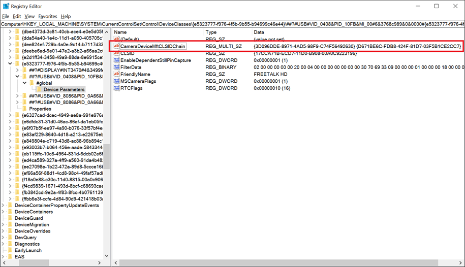
CameraDeviceMftCLSIDChain (REG_MULTI_SZ) %Dmft0.CLSID%,%Dmft.CLSID%,%Dmft2.CLSID%
As shown in the sample INF settings below (replace the %Dmft0.CLSID% and % Dmft1.CLSID% with the actual CLSID strings you're using for your DMFTs), there are maximum of 2 CLSIDs allowed in Windows 10, version 1703, and the first one is closest to DevProxy and the last one is the last DMFT in the chain.
Platform DMFT CLSID is {3D096DDE-8971-4AD5-98F9-C74F56492630}.
Some example CameraDeviceMftCLSIDChain settings:
No IHV/OEM DMFT or Platform DMFT
- CameraDeviceMftCLSIDChain = "" (or no need to specify this registry entry)
IHV/OEM DMFT
- CameraDeviceMftCLSIDChain = %Dmft.CLSID%
Platform DMFT <-> IHV/OEM DMFT
CameraDeviceMftCLSIDChain = "{3D096DDE-8971-4AD5-98F9-C74F56492630}",%Dmft.CLSID%
Here's a screenshot of the result registry key for a USB camera with Platform DMFT and a DMFT (with GUID {D671BE6C-FDB8-424F-81D7-03F5B1CE2CC7}) in the chain.
IHV/OEM DMFT0 <-> IHV/OEM DMFT1
- CameraDeviceMftCLSIDChain = %Dmft0.CLSID%,%Dmft1.CLSID%,
Note
The CameraDeviceMftCLSIDChain can have a maximum 2 of CLSIDs.
If CameraDeviceMftCLSIDChain is configured, the legacy CameraDeviceMftCLSID settings are skipped by DTM.
If CameraDeviceMftCLSIDChain isn't configured and the legacy CameraDeviceMftCLSID is configured, then the chain would look like (if its USB camera and supported by Platform DMFT and Platform DMFT is enabled) DevProxy <–> Platform DMFT <–> OEM/IHV DMFT or (if the camera isn't supported by Platform DMFT or Platform DMFT is disabled) DevProxy <-> OEM/IHV DMFT.
Example INF file settings:
[USBVideo.Interface.AddReg]
HKR,,CLSID,,%ProxyVCap.CLSID%
HKR,,FriendlyName,,%USBVideo.DeviceDesc%
HKR,,RTCFlags,0x00010001,0x00000010
HKR,,EnablePlatformDmft,0x00010001,0x00000001
HKR,,DisablePlatformDmftFeatures,0x00010001,0x00000001
HKR,,CameraDeviceMftCLSIDChain, 0x00010000,%Dmft0.CLSID%,%Dmft1.CLSID%
Com object and MFT registration of Device MFTs
Rather than registering the driver COM object globally, the driver COM object is registered under the device key. This allows MFT COM registration from within the container and prevents global registry keys being created, thus preserving driver package isolation. MFTs are registered under the device key as well for similar reasons.
Changes to driver INF
Upon device driver installation, the INF must now make all COM object and MFT registrations under the device key. MFT and COM registrations must change as shown here:
MFT registrations
| Before | After |
|---|---|
| INF AddReg: HKCR, MediaFoundation\Transforms\{clsid}\... |
Per-Instance device software INF AddReg: HKR, MediaFoundation\Transforms\{clsid}\... |
| Registry Location: HKLM\SOFTWARE\Classes\MediaFoundation\Transforms\{clsid}\... |
Registry Locations: software key\MediaFoundation\Transforms\{clsid}\... |
COM registrations
In Windows 26100 and later, all COM registration for Device MFTs must use AddComServer/AddComClass directives in the INF. A syntax example is shown here:
[AvsCamera.COM]
AddComServer = AvsCameraMFT,,AvsCamera.COMInstall

[AvsCamera.COMInstall]
ServerType = 1; in-proc
ServerBinary = %13%\AvsCameraDMFT.dll
AddComClass = %DMFT.CLSID%,, AvsCamera.COMClassInstall


[AvsCamera.COMClassInstall]
ThreadingModel = Both
Description = %AvsCamera.ComServerDescription%
Previous versions of Device MFT COM Registration used AddReg to manually install the COM class.
| Before | After |
|---|---|
| INF AddReg: HKLM,Software\Classes\CLSID\{clsid}\... HKCR,CLSID\{clsid}\... HKCR,Wow6432Node\CLSID\{clsid}\... HKCR,WowAA32Node\CLSID\{clsid}\... |
Per-Instance device software INF AddReg: HKR,Classes\CLSID\{clsid}\... HKR,Classes\CLSID\{clsid}\... HKR,Classes\Wow6432Node\CLSID\{clsid}\... HKR,Classes\WowAA32Node\CLSID\{clsid}\... |
The INF syntax for differentiating based on OS version can be found in Combining platform extensions with operating system versions. Starting in Window 11 25300, the INF must conform to these new registry keys. Older OS versions use the traditional registry keys for compatibility. The INF must set up these registry keys in the old location on older OS builds and create the new keys in their new location for newer OS builds. For example, for an MFT registration on an older build the INF creates the key under the following registry entry:
HKLM\SOFTWARE\Classes\MediaFoundation\Transforms\{clsid}\
For an MFT registration on a new build, the INF creates the key under the following registry entry:
**software key**\MediaFoundation\Transforms\{clsid}\
This entry defines where software key represents a device's software key.
For more information, see Opening a device's software key.
A syntax example of targeting different OS versions is shown here:
[Manufacturer]
%Msft% = Msft, NTamd64,NTamd64.10.0...25300

; -------------- ;
; Models Section ;
; -------------- ;

; Targets old builds
[Msft.NTamd64]
%DeviceDesc% = ExampleDDInstall_Old, ExampleHardwareId

[ExampleDDInstall_Old]
 AddReg = MFT_Registration_Old

[MFT_Registration_Old]
; INF work for older build here

; Windows 10 build with build number equal to or greater than 25300
[msft.ntamd64.10.0...25300]
%DeviceDesc% = ExampleDDInstall_New, ExampleHardwareId

[ExampleDDInstall_new]
AddReg = MFT_Registration_new

[MFT_Registration_new]
; INF work for newer build here