Note
Access to this page requires authorization. You can try signing in or changing directories.
Access to this page requires authorization. You can try changing directories.
1 Overview
1.1 Summary
Microsoft extensions to the USB Video Class specification enable new controls and the capability to carry well-defined frame-metadata in a standard format.
1.2 Architecture Decisions
The USB Video Class (UVC) frame metadata support is available to ISOCH and BULK endpoints. However, in the case of BULK endpoint, the metadata size is limited to 240 bytes (because all video frame data is transferred in a single video frame packet on BULK endpoints).
UVC metadata support is only available to frame based payloads.
UVC metadata support is available only through the Media Foundation (MF) capture pipeline.
UVC metadata is opt-in. Every IHV/OEM that needs metadata support must be enabled through a custom INF file.
UVC metadata only supports system allocated memory. VRAM or DX surfaces won't be supported.
2 Architectural Overview
2.1 Description
2.2.1 Capability discovery through INF
2.2.1.1 Still Image Capture – Method 2
Some existing UVC devices may not support Method 2 described in section 2.4.2.4 (Still Image Capture) of the UVC 1.5 Class specification.pdf that can be downloaded at the USB Video Class specification web site.
In Windows 10, version 1607 and earlier, the capture pipeline didn't use Method 2, even if a device advertised support for it per the UVC 1.5 spec.
In Windows 10, version 1703, devices that use this method must use a custom INF file for the camera driver, but a custom INF is required for the given hardware to enable Method 2 still image capture).
Note: The camera driver can be based on the Windows USBVIDEO.SYS or can be based on a custom driver binary.
The custom INF file, based on either custom UVC driver or inbox UVC driver, should include the following AddReg entry:
EnableDependentStillPinCapture: REG_DWORD: 0x0 (Disabled) to 0x1 (Enabled)
When this entry is set to Enabled (0x1), the capture pipeline uses Method 2 for Still Image Capture (assuming the firmware also advertises support for Method 2 as specified by UVC 1.5 spec).
An example for the custom INF section would be as follows:
[USBVideo.NT.Interfaces]
AddInterface=%KSCATEGORY_CAPTURE%,GLOBAL,USBVideo.Interface
AddInterface=%KSCATEGORY_RENDER%,GLOBAL,USBVideo.Interface
AddInterface=%KSCATEGORY_VIDEO%,GLOBAL,USBVideo.Interface
AddInterface=%KSCATEGORY_RENDER_EXT%,GLOBAL,USBVideo.Interface
AddInterface=%KSCATEGORY_VIDEO_CAMERA%,GLOBAL,USBVideo.Interface

[USBVideo.Interface]
AddReg=USBVideo.Interface.AddReg

[USBVideo.Interface.AddReg]
HKR,,CLSID,,%ProxyVCap.CLSID%
HKR,,FriendlyName,,%USBVideo.DeviceDesc%
HKR,,RTCFlags,0x00010001,0x00000010
HKR,,EnableDependentStillPinCapture,0x00010001,0x00000001
2.2.2 Extension Unit Controls
Microsoft's extension to the USB Video Class specification for enabling new controls is done through an extension unit identified by GUID MS_CAMERA_CONTROL_XU (referred to as Microsoft-XU).
// {0F3F95DC-2632-4C4E-92C9-A04782F43BC8}
DEFINE_GUID(MS_CAMERA_CONTROL_XU,
    0xf3f95dc, 0x2632, 0x4c4e, 0x92, 0xc9, 0xa0, 0x47, 0x82, 0xf4, 0x3b, 0xc8);
A Microsoft-XU implemented by the device firmware houses the new controls defined in the following subsections. The following request definitions apply to all these controls unless an overriding definition is specified explicitly for that control. Refer to UVC 1.5 Class specification.pdf for definitions of D3, D4, GET_INFO, and so on.
GET_INFO request shall report the control without AutoUpdate and Asynchronous capabilities (for example, D3 and D4 bits shall be set to 0).
GET_LEN request shall report the maximum length of the payload for this control (wLength).
GET_RES request shall report the resolution (step-size) for qwValue/dwValue. All other fields shall be set to 0.
GET_MIN request shall report the minimum supported value for qwValue/dwValue. All other fields shall be set to 0.
GET_MAX request shall report the maximum supported value for qwValue/dwValue. In addition, all supported flags shall be set to 1 in bmControlFlags. All other fields shall be set to 0.
GET_DEF and GET_CUR requests shall report the default and current settings respectively for the fields qwValue/dwValue and bmControlFlags. All other fields shall be set to 0.
A SET_CUR request is issued by host after setting all fields.
The following table maps the control selectors for Microsoft-XU to their respective values and the bit position for the bmControls field in Extension Unit Descriptor:
| Control Selector | Value | Bit Position (bmControls Field) |
|---|---|---|
| MSXU_CONTROL_UNDEFINED | 0x00 | NA |
| MSXU_CONTROL_FOCUS | 0x01 | D0 |
| MSXU_CONTROL_EXPOSURE | 0x02 | D1 |
| MSXU_CONTROL_EVCOMPENSATION | 0x03 | D2 |
| MSXU_CONTROL_WHITEBALANCE | 0x04 | D3 |
| Reserved for future use | 0x05 | D4 |
| MSXU_CONTROL_FACE_AUTHENTICATION | 0x06 | D5 |
| MSXU_CONTROL_CAMERA_EXTRINSICS | 0x07 | D6 |
| MSXU_CONTROL_CAMERA_INTRINSICS | 0x08 | D7 |
| MSXU_CONTROL_METADATA | 0x09 | D8 |
| MSXU_CONTROL_IR_TORCH | 0x0A | D9 |
| MSXU_CONTROL_DIGITALWINDOW | 0X0B | D10 |
| MSXU_CONTROL_DIGITALWINDOW_CONFIG | 0X0C | D11 |
| MSXU_CONTROL_VIDEO_HDR | 0X0D | D12 |
| MSXU_CONTROL_FRAMERATE_THROTTLE | 0x0E | D13 |
| MSXU_CONTROL_FIELDOFVIEW2_CONFIG | 0x0F | D14 |
| MSXU_CONTROL_FIELDOFVIEW2 | 0x10 | D15 |
2.2.2.1 Cancelable Controls
A Cancelable control is defined here by using the Autoupdate capability.
GET_INFO request shall report such control as an Autoupdate Control (for example, D3 bit shall be set to 1) but not as an Asynchronous control (for example, D4 bit shall be set to 0).
For such control, a SET_CUR request can be issued to set a new value (a SET_CUR(NORMAL) request wherein bmOperationFlags:D0 bit is set to 0) or cancel a previous SET_CUR(NORMAL) request (a SET_CUR(CANCEL) request wherein bmOperationFlags:D0 bit is set to 1). A SET_CUR request should be completed by the device immediately as soon as the request is received (even though the hardware isn't configured or converged to the new settings requested). For each SET_CUR(NORMAL) request, the device produces a corresponding Control Change interrupt for this control raised when the new settings have been applied or when a SET_CUR(CANCEL) request arrives; until this interrupt arrives, the SET_CUR(NORMAL) request is considered to be in-progress. When a SET_CUR(NORMAL) request is in-progress, additional SET_CUR(NORMAL) requests for this particular control shall result in a failure. A SET_CUR(CANCEL) request shall always succeed. If there's nothing to cancel, then the device just does nothing.
The Control Change interrupt payload shall have the bit bmOperationFlags:D0 set to 0 if the settings specified by SET_CUR(NORMAL) were applied (for example, convergence happened) and set to 1 if the settings weren't applied because of a SET_CUR(CANCEL) request that came after the SET_CUR(NORMAL) request (for example, convergence hasn't happened yet).
2.2.2.2 Focus Control
This control allows the host software to specify the focus settings for the camera. This is a global control that affects all endpoints on all video streaming interfaces associated with the video control interface.
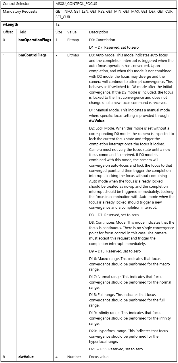
This control shall function as a Cancelable Control (see section 2.2.2.1 for GET_INFO request requirements and functional behavior of SET_CUR request).
GET_MAX requirement: This control shall advertise support for bits D0, D1, D2, D8, and D18 in bmControlFlags.
GET_DEF requirement: The default for bmControlFlags shall be D0 and D18 set to 1 and dwValue set to 0.
For GET_CUR/SET_CUR requests, the following restrictions apply for field bmControlFlags:
Among D0, D1 and D8 bits, only one bit can be set; none of them being set is valid too if D2 bit is set.
Among D16, D17, D18, D19, and D20, only one bit can be set, none of them being set is valid too.
D1 is incompatible with all other bits currently defined (D0, D2, D8, D16, D17, D18, D19, and D20).
D2 is incompatible with D1 and D8.
D2 is incompatible with D16, D17, D18, D19, and D20 if D0 isn't set.
2.2.2.3 Exposure Control
This control allows the host software to specify the exposure settings for the camera. This is a global control that affects all endpoints on all video streaming interfaces associated with the video control interface.
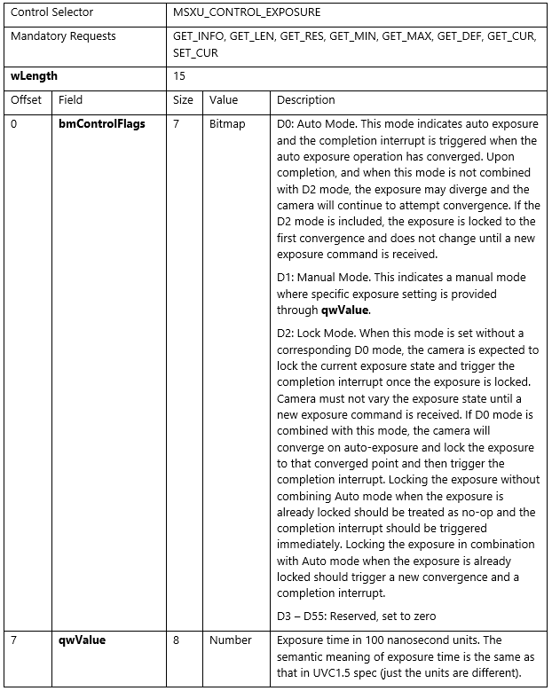
GET_INFO request shall report this control as an Asynchronous control (for example, D4 bit shall be set to 1) but not as an AutoUpdate control (for example, D3 bit shall be set to 0).
GET_MAX requirement: This control shall advertise support for bits D0, D1, and D2 in bmControlFlags.
GET_DEF requirement: The default for bmControlFlags shall be D0 set to 1 and qwValue set to 0.
For GET_CUR/SET_CUR requests, the following restrictions apply for field bmControlFlags:
- Among D0, D1 and D2 bits, at least one bit shall be set.
- D1 is incompatible with D0 and D2.
2.2.2.4 EV Compensation Control
This control allows the host software to specify the EV compensation settings for the camera. This is a global control that affects all endpoints on all video streaming interfaces associated with the video control interface.
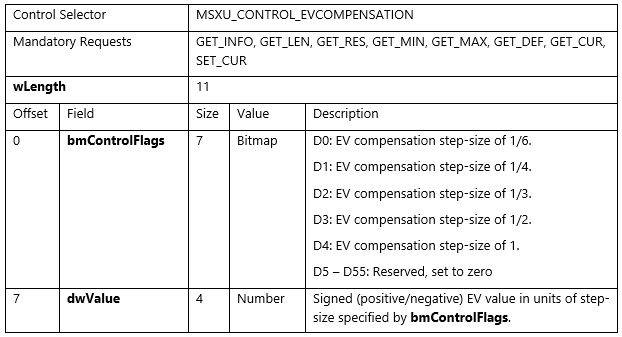
GET_INFO request shall report this control as an Asynchronous control (for example, D4 bit shall be set to 1) but not as an AutoUpdate control (for example, D3 bit shall be set to 0).
GET_RES request shall report all the supported resolutions (step-size) by setting corresponding bits in bmControlFlags. All other fields shall be set to 0.
GET_MIN and GET_MAX requests shall report the minimum and maximum supported value for dwValue. The bit D4 (indicating step-size of 1) shall be the one and only bit set in bmControlFlags. All other fields shall be set to 0.
GET_DEF, GET_CUR, SET_CUR requests shall follow the definitions in section 2.2.2.1 but shall have one and only one bit set among D0, D1, D2, D3, and D4 bits for field bmControlFlags. Furthermore, GET_DEF request shall have dwValue set to 0.
2.2.2.5 White Balance Control
This control allows the host software to specify the white balance settings for the camera. This is a global control that affects all endpoints on all video streaming interfaces associated with the video control interface.
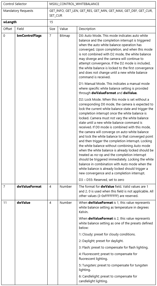
GET_INFO request shall report this control as an Asynchronous control (for example, D4 bit shall be set to 1) but not as an AutoUpdate control (for example, D3 bit shall be set to 0).
GET_RES, GET_MIN, GET_MAX requests shall follow the definitions in section 2.2.2.1 but shall have dwValueFormat set to 1.
GET_MAX requirement: This control shall advertise support for bits D0, D1, and D2 in bmControlFlags.
GET_DEF requirement: The default for bmControlFlags shall be D0 set to 1 and dwValueFormat and dwValue set to 0.
For GET_CUR/SET_CUR requests, the following restrictions apply for field bmControlFlags:
- Among D0, D1 and D2 bits, at least one bit shall be set.
- D1 is incompatible with D0 and D2.
2.2.2.6 Face Authentication Control
This control allows the host software to specify whether the camera supports streaming modes that are used for face authentication. Support for this control implies that the camera is capable of face authentication. This control shall not be supported otherwise.
This control is only applicable to cameras that can produce Infra-Red (IR) data and is only applicable to the specified streaming interfaces (which is a subset of all video streaming interfaces associated with the video control interface).
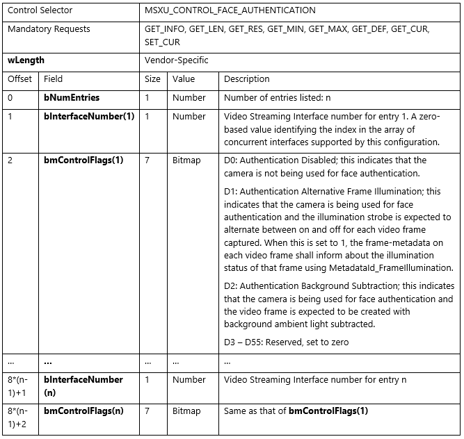
GET_RES and GET_MIN requests shall report field bNumEntries set to 0 and hence have no additional fields.
For a GET_MAX request, a bit set to 1 on the bmControlFlags field indicates that the corresponding mode is supported for that streaming interface. A GET_MAX request output shall list all and only the streaming interfaces capable of either D1 or D2 (for example, if a streaming interface is capable of either D1 or D2, it gets listed; otherwise, it doesn't get listed). Also, no streaming interface shall be advertised to be capable of both D1 and D2. If a streaming interface is also intended for use in a general purpose manner (for example, outside of the purpose of face authentication), then D0 shall be set to 1 for that streaming interface (in addition to D1/D2).
For GET_DEF / GET_CUR / SET_CUR requests, a bit set to 1 on the bmControlFlags field indicates that the corresponding mode is chosen for that streaming interface. In these requests, one and only one bit (among D0, D1 & D2) shall be set for a particular streaming interface. For the GET_DEF request that returns the default choice (which is implementation specific), if a streaming interface is also intended for use in a general purpose manner (for example, outside of the purpose of face authentication), then D0 shall be set to 1 by default on that streaming interface; otherwise, either D1 or D2 (but not both) shall be set to 1 by default. A GET_DEF / GET_CUR request output shall contain information on all streaming interfaces listed in GET_MAX request output, however, a SET_CUR request may only include a subset of the streaming interfaces listed in GET_MAX request output.
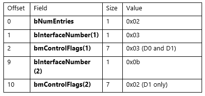
Example:
Let us assume that a camera has four video streaming interfaces with numbers 0x03, 0x05, 0x08, and 0x0b respectively wherein video streaming interface 0x05 produces RGB data and the remaining three video streaming interfaces produce IR data. Among the streaming interfaces that produce IR data, let us assume streaming interfaces 0x03 and 0x0b are both capable of D1, but streaming interface 0x03 is also capable of D0. In this example, the face authentication control is only applicable to the streaming interfaces numbered 0x03 and 0x0b and hence only these interfaces appear in the requests.
The output for GET_MAX request shall be the following:
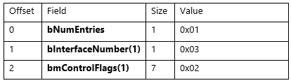
The output for GET_DEF request shall be the following:

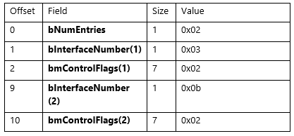
A SET_CUR request to change the setting on streaming interface 0x03 to D1 would be as follows:
The output for a GET_CUR request after the above SET_CUR request shall be as follows:
2.2.2.7 Camera Extrinsics Control
This control allows the host software to obtain the camera extrinsics data for endpoints on video streaming interfaces associated with the video control interface. The data thus obtained for each endpoint shows up as attribute MFStreamExtension_CameraExtrinsics on the attribute store for the corresponding stream (obtained using IMFDeviceTransform::GetOutputStreamAttributes call).
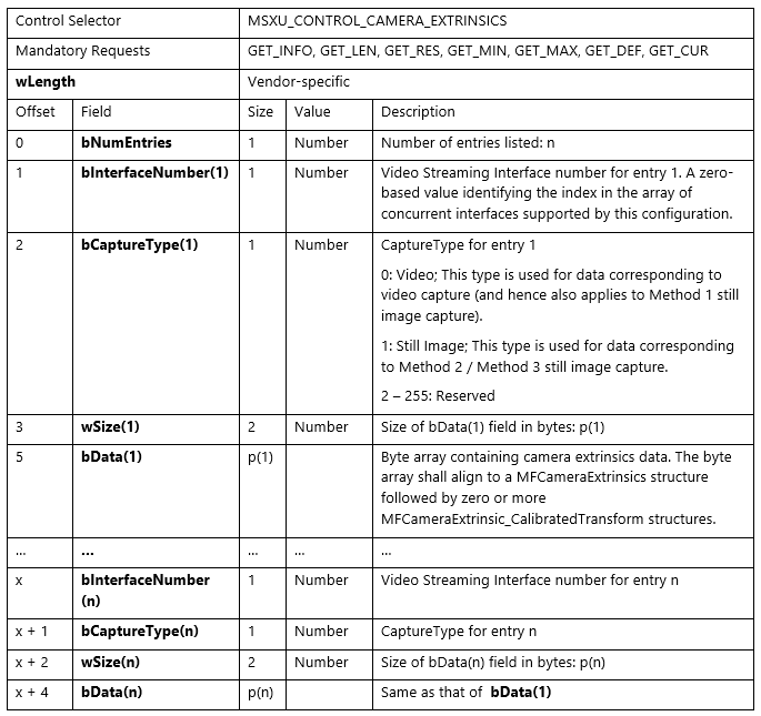
GET_RES, GET_MIN, GET_MAX, GET_CUR requests shall report field bNumEntries set to 0 and hence have no additional fields.
GET_DEF request shall list all endpoints that have the extrinsics information available.
Example:
Let's assume that a camera has three video streaming interfaces with numbers 0x03, 0x05, and 0x08 respectively wherein video streaming interface 0x05 supports still image capture using method 2 in addition to the video capture supported by all video streaming interfaces. Among these streaming interfaces, let us assume streaming interfaces 0x05 and 0x08 have extrinsics information available while streaming interface 0x03 doesn't have the extrinsics information available.
In this example, the output for GET_DEF request shall be the following:

2.2.2.8 Camera Intrinsics Control
This control allows the host software to obtain the camera intrinsics data for endpoints on video streaming interfaces associated with the video control interface. The data thus obtained for each endpoint shows up as attribute MFStreamExtension_PinholeCameraIntrinsics on the attribute store for the corresponding stream (obtained using IMFDeviceTransform::GetOutputStreamAttributes call).
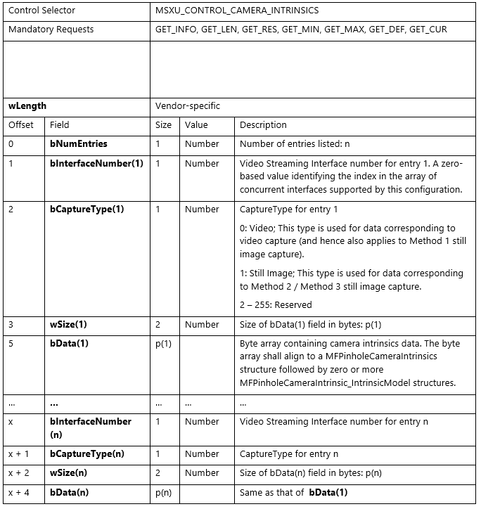
GET_RES, GET_MIN, GET_MAX, GET_CUR requests shall report field bNumEntries set to 0 and hence have no additional fields.
GET_DEF request shall list all endpoints that have the intrinsics information available.
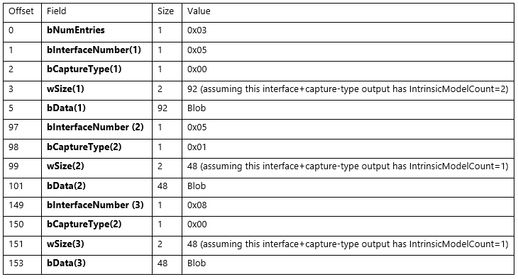
Example:
Let's assume that a camera has three video streaming interfaces with numbers 0x03, 0x05, and 0x08 respectively wherein video streaming interface 0x05 supports still image capture using method 2 in addition to the video capture supported by all video streaming interfaces. Among these streaming interfaces, let us assume streaming interfaces 0x05 and 0x08 have intrinsics information available while streaming interface 0x03 doesn't have the intrinsics information available.
In this example, the output for GET_DEF request shall be the following:
2.2.2.9 Metadata Control
This control allows the host software to query and control metadata produced by the camera. This is a global control that affects all endpoints on all video streaming interfaces associated with the video control interface.
This control gets mapped to KSPROPERTY_CAMERACONTROL_EXTENDED_METADATA by the camera driver.
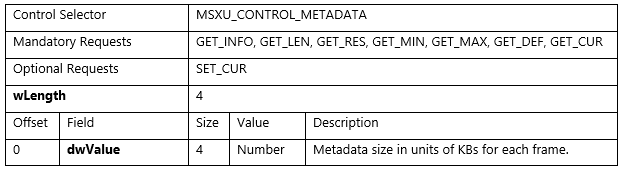
If SET_CUR request is supported by the firmware, the following applies:
GET_MIN, GET_DEF requests shall report field dwValue set to 0.
GET_RES request shall report field dwValue to be the same value as reported by GET_MAX request.
When a SET_CUR request is received with dwValue set to 0, the camera shall not produce any metadata. When a SET_CUR request is received with dwValue set to be the same value as reported by GET_MAX request, the camera can produce metadata and the size of such metadata can't exceed dwValue for any frame.
If SET_CUR request isn't supported by the firmware, the following applies:
GET_MIN, GET_DEF requests shall report field dwValue to be the same value as reported by GET_MAX request.
GET_RES request shall report field dwValue set to 0.
The camera can produce metadata and the total size of such metadata can't exceed the dwValue - as reported by GET_MAX request – times 1024 bytes less the size of a UsbVideoHeader metadata payload, for any frame.
A UsbVideoHeader metadata payload is the sizeof(KSCAMERA_METADATA_ITEMHEADER) + sizeof(KSTREAM_UVC_METADATA) or 24 bytes.
The metadata produced shall conform to the Microsoft standard-format metadata described in section 2.2.3.
2.2.2.10 IR Torch Control
This control provides a flexible means for the IR LED hardware to report the extent to which it can be controlled and provides the ability to control it. This is a global control that affects all endpoints on all video streaming interfaces associated with the video control interface by adjusting the power to an IR lamp connected to the camera.
This control gets mapped to KSPROPERTY_CAMERACONTROL_EXTENDED_IRTORCHMODE by the camera driver.
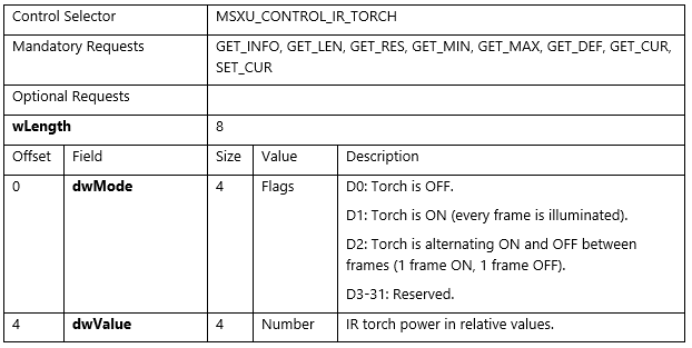
The following applies:
GET_LEN request shall report a value of 8.
GET_INFO request shall report a value of 3. This value indicates a synchronous control that supports GET_CUR and SET_CUR.
GET_MIN request shall report field dwMode set to 0 and dwValue set to a value indicating minimum power. A power level of 0 may indicate OFF, but the minimum operational power level need not be 0.
GET_RES request shall report field dwMode set to 0 and dwValue set to a number less than or equal to GET_MAX(dwValue) – GET_MIN(dwValue) and such that GET_MAX(dwValue) – GET_MIN(dwValue) is evenly divisible by that value. dwValue may not be zero (0).
GET_MAX request shall report field dwMode set with bits D[0-2] set to identify the capabilities of this control. dwMode must have bit D0 set, indicating that OFF is supported, and it must have at least one other bit set, supporting an active state. dwValue must be set to a value indicating normal power.
GET_DEF request shall report field dwMode set to the default mode the system should be in before streaming begins. dwMode must be set to 2 (ON) or 4 (ALTERNATING). dwValue should be set to the power level normally used for the FaceAuth control. dwValue is defined by the manufacturer.
GET_CUR request shall report field dwMode set to the current operating mode and dwValue set to the current illumination.
When a SET_CUR request is received, the IR Torch sets the illumination to a prorate intensity using the requested operating mode.
The IR Torch must emit the MF_CAPTURE_METADATA_FRAME_ILLUMINATION attribute for every frame. It can provide this through a Device MFT or by including a MetadataId_FrameIllumination attribute in the metadata payload from the camera. See section 2.2.3.4.4.
This metadata's sole purpose is to indicate whether a frame is illuminated or not. This is the same metadata required by the KSPROPERTY_CAMERACONTROL_EXTENDED_FACEAUTH_MODE DDI and the MSXU_FACE_AUTHENTICATION_CONTROL defined in section 2.2.2.6.
2.2.2.11 Digital Window Control
Digital Window specifies the field of view and zoom of the camera while camera is streaming. This control is a potential substitute for Pan, Tilt, and Zoom. This control only applies while the camera is actively streaming.
This control is available to all types of cameras and is independent of media type being streamed.
This control allows the host software to query and control the digital window associated with a camera.
This is a global control that affects all endpoints on all video streaming interfaces associated with the video control interface. It adjusts the source of pixel data used by the ISP. This includes Method 2 and Method 3 still capture pins.
This control is mapped to KSPROPERTY_CAMERACONTROL_EXTENDED_DIGITALWINDOW by the inbox camera driver.

The following applies:
GET_LEN request shall report a value of 16.
GET_INFO request shall report a value of 3. This value indicates a synchronous control that supports GET_CUR and SET_CUR.
GET_MIN request shall report field dwMode set to 0, OriginX and OriginY set to 0.0 and WindowSize set to 1.0. This request is currently unused.
GET_RES request shall report field dwMode set to 0, OriginX and OriginY set to 0.0 and WindowSize set to 1.0. This request is currently unused.
GET_MAX request shall report field dwMode set with bit D0 set to identify the capabilities of this control. A value of 0 indicates that only manual mode is supported. A value of 1 indicates that auto face-framing mode is supported. The rest of these fields are unused, however, we recommend OriginX and OriginY be set to 0.0 and WindowSize set to 1.0.
GET_DEF request shall report field dwMode set to 0, OriginX and OriginY set to 0.0 and WindowSize set to 1.0. This is always the default window.
GET_CUR request shall report field dwMode set to the current operating mode and OriginX, OriginY and WindowSize describe the current digital window.
When a SET_CUR request is received, the camera adjusts its field of view to match the selected operating mode and digital window.
If auto face-framing mode is selected, the camera selects a window that fully encompasses the dominate face in the scene and the OriginX, OriginY, and WindowSize passed in are ignored. If no face is found, the default window is used.
Any changes to the digital window must be reflected in each sample's metadata payload.
Changes to the digital window may not be immediately effective, but the control should respond immediately. Changes to the digital window must be reported in the frame's metadata payload as soon as they go into effect.
2.2.2.12 Digital Window Config Control
Digital Window Config Caps control specifies the scaling limits of the camera given all available resolutions. Resolutions are independent of media type, so two media types advertising the same display resolution are combined into one capability.
Due to the size limitations of a control endpoint, this control can describe at most 1820 unique resolutions.
This control must always be available to report the capabilities of the Digital Window control if that control is also present.
This control is mapped to KSPROPERTY_CAMERACONTROL_EXTENDED_DIGITALWINDOW_CONFIGCAPS by the inbox camera driver.
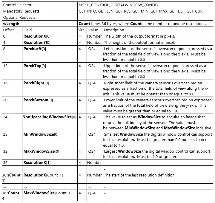
The following applies:
GET_LEN request shall report the entire size of the payload. The payload size must be a multiple of 36 as each resolution definition is 36 bytes in length.
GET_INFO request shall report a 1. This value indicates a synchronous control that supports only GET_CUR.
GET_CUR request shall report an array of capabilities. The fields of the capability structure are defined above.
GET_MIN, GET_MAX, GET_RES and GET_DEF requests are unused, but should return the same values as GET_CUR.
SET_CUR requests aren't supported.
2.2.2.13 Video HDR Control
This control allows the host software to specify whether the camera supports Video HDR. Support for this control implies that the camera is capable of performing video HDR as the best effort. If camera doesn't support Video HDR then, it must not implement this control.
This control gets mapped to KSPROPERTY_CAMERACONTROL_EXTENDED_VIDEOHDR by the camera driver.
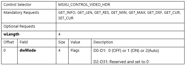
The following applies:
GET_LEN request shall report the entire size of the payload (for example, 4 bytes).
GET_INFO request shall report a value 3. This value indicates a synchronous control that supports GET_CUR, SET_CUR.
GET_CUR request shall report field dwMode set to the current operating mode.
GET_DEF shall have a dwMode set to OFF (0).
GET_MAX request shall advertise support for available modes of operations: [1 (ON/OFF), 3 (ON/OFF/Auto)]. Support for ON (1) is mandatory for this control.
GET_MIN and GET_RES requests shall report 0.
SET_CUR request should set the mode to either OFF (0), ON (1), or AUTO (2).
2.2.2.14 Framerate Throttle Control
This control allows the host software to specify whether the camera supports Framerate throttle.
This control only applies while the camera is actively streaming. To be actively streaming means a preview or record pin must be in KSSTATE_RUN, ready and able to deliver frames. On a set if a stream isn't active, then this control should return STATUS_INVALID_DEVICE_STATE.
Even if this is a filter scope control, the frame rate control shouldn't impact the photo pin or no-RGB streams such as IR/depth. Also, when the Frame rate throttle is in effect the sample duration should also be adjusted accordingly.
This control gets mapped to KSPROPERTY_CAMERACONTROL_EXTENDED_FRAMERATE_THROTTLE by the camera driver.
| Control selector | MSXU_CONTROL_FRAMERATE_THROTTLE |
|---|---|
| Mandatory Requests | GET_INFO, GET_LEN, GET_RES, GET_MIN, GET_MAX, GET_DEF, GET_CUR, SET_CUR |
| Optional Requests | |
| wLength | 20 |
| Offset | Field | Size | Value | Description |
|---|---|---|---|---|
| 0 | dwMode | 4 | Flags | D0: 0 (OFF) or 1 (ON) D1-D31: reserved and set to 0 |
| 4 | scaleFactorPercentage | 4 | Number | This value should be within the range of Min and Max, and it should be set to a multiple of Step value. For example: if Min = 5, Max = 100 and Step = 5 and if an application decided to reduce the frame rate to 80% of original value, then this member value should be set to 80. By setting this value appropriately an app can make sure that the new frame rate never exceeds the original value, nor goes to zero, but original frame rate is possible. |
| 8 | min | 4 | Number | Min should be equal to at-lease one step size or it should be a multiple of step size, (Example: step1, Step2 etc.). Min value can't be set to 0. |
| 12 | max | 4 | Number | Max must be set to 100, meaning no change in frame rate. |
| 16 | step | 4 | Number | Step should be a strict factor of Max, for example, {Max % Step == 0}. Example: 1, 2, 4, 5 etc. |
The following applies:
GET_LEN request shall report the entire size of the payload (for example, 20 bytes).
GET_INFO request shall report a value 3. This value indicates a synchronous control that supports GET_CUR, SET_CUR.
GET_CUR request shall report field dwMode set to the current operating mode and scaleFactorPercentage set to current scaleFactor value. Min, max, and step should report the values as described in above table.
GET_DEF shall have a dwMode set to OFF(0), scaleFactorPercentage=100, Min set to default minimum value, max set to 100 and, step set to default step value. The values of min and step should be defined by the manufacturer, but should follow the guidelines mentioned in the above table.
GET_ MAX request shall advertise support for available modes of operations and will report value 1 [ ON | OFF ]. Support for both ON and OFF is mandatory for this control. Min, max, step, and scaleFactorPercentage can be set to the default values.
GET_MIN and GET_RES requests shall report 0.
SET_CUR request should set the mode to either OFF(0), ON(1). If dwMode is set to ON, then scaleFactorPercentage shall take effect. For both OFF and ON cases, the scaleFactorPercentage must be valid as described in the above table.
2.2.2.15 Field of View 2 Config Control
Field of View 2 Config control specifies the supported diagonal Field of View degree values as an array of values. All supported values must be in the range of theoretical min and max, 1 degree - 360 degrees.
If the device wants to support continuous Field of View values, it needs to report all supported values. For example, if the device wants to support diagonal Field of View from 85 degrees - 60 degrees with step size of 1, this control needs to report array of values [85, 84, 83, 82, …, 62, 61, 60].
This control must be available to report the capabilities when Field of View 2 control is present.
This is synchronous filter level control.
This control is mapped to KSPROPERTY_CAMERACONTROL_EXTENDED_ FIELDOFVIEW2_CONFIGCAPS by the camera driver.
| Control selector | MSXU_CONTROL_FIELDOFVIEW2_CONFIG |
|---|---|
| Mandatory Requests | GET_INFO, GET_LEN, GET_RES, GET_MIN, GET_MAX, GET_DEF, GET_CUR |
| Optional Requests | |
| wLength | 4 bytes + Count times 4 bytes, where Count is the number of unique Field of View values. |
| Offset | Field | Size | Value | Description |
|---|---|---|---|---|
| 0 | dwDefaultFieldOfView | 4 | Number | The default diagonal Field of View must be one of the values reported in FieldOfViewValues array. |
| 4 | FieldOfViewValues[0] | 4 | Number | First Field of View value, this must be the widest FoV (Field of View) value. |
| … | … | … | … | … |
| 4 + 4*(Count-1) | FieldOfViewValues [Count -1] | 4 | Number | Last Field of View value, this must be the narrowest FoV value. |
The following applies:
GET_LEN request shall report the entire size of the payload.
GET_INFO request shall report a 1. This value indicates a synchronous control that supports only GET_CUR.
GET_CUR request shall report data that contains default FoV and array of supported FoV values in descending order. The fields of the structure are defined above.
GET_DEF request shall report same as GET_CUR.
GET_MIN, GET_MAX and GET_RES requests are unused, but should return the same values as GET_CUR.
SET_CUR requests aren't supported.
Field of View values must be in descending order, for example, the widest Field of View is first and the narrowest is last.
2.2.2.16 Field of View 2 Control
This control specifies the base field of view that the camera is using when streaming. This control can be applied before or during streaming.
This control is available to all types of cameras and is independent of media type being streamed.
This control allows the host software to query and control the field of view associated with a camera.
This is a global control that affects all endpoints on all video streaming interfaces associated with the video control interface. It adjusts the source of pixel (or sensor) data used by the ISP (Image Signal Processor). This includes Method 2 and Method 3 still capture pins.
This is synchronous filter level control.
This control is mapped to KSPROPERTY_CAMERACONTROL_EXTENDED_ FIELDOFVIEW2 by the camera driver.
| Control selector | MSXU_CONTROL_FIELDOFVIEW2 |
|---|---|
| Mandatory Requests | GET_INFO, GET_LEN, GET_RES, GET_MIN, GET_MAX, GET_DEF, GET_CUR, SET_CUR |
| Optional Requests | |
| wLength | 4 |
| Offset | Field | Size | Value | Description |
|---|---|---|---|---|
| 0 | dwValue | 4 | Number | Diagonal Field of View value in degrees. |
The following applies:
GET_LEN request shall report a value of 4.
GET_INFO request shall report a 3. This value indicates a synchronous control that supports GET_CUR and SET_CUR.
GET_MIN request shall report field dwValue set to minimum supported Field of View value.
GET_RES request shall report field dwValue set 0. This request is currently unused.
GET_MAX request shall report field dwValue set to maximum supported Field of View value.
GET_DEF request shall report field dwValue set to default Field of View value.
GET_CUR request shall report field dwValue set to current Field of View value.
When a SET_CUR request is received, the camera sets its field of view to match the given dwValue.
If the camera implements CT_ZOOM_RELATIVE_CONTROL and/or CT_ZOOM_ABSOLUTE_CONTROL, these controls shall reset to their default values when MSXU_CONTROL_FIELDOFVIEW2 SET_CUR is called.
If the camera implements MSXU_CONTROL_DIGITALWINDOW, it shall reflect the window change when a new Field of View value is set. And vice versa, the Field of View shall reflect the changes made via Digital Window. See KSPROPERTY_CAMERACONTROL_EXTENDED_ FIELDOFVIEW2 for details.
2.2.3 Metadata
The design for standard-format frame-metadata builds on the UVC custom metadata design from Windows 10. In Windows 10, custom metadata is supported for UVC by using a custom INF for the camera driver (note: the camera driver can be based on the Windows USBVIDEO.SYS, but a custom INF is required for the given hardware for metadata to come through). If MetadataBufferSizeInKB<PinIndex> registry entry is present and nonzero, then custom metadata is supported for that pin and the value indicates the buffer size used for the metadata. The <PinIndex> field indicates a 0 based index of the video pin index.
In Windows 10, version 1703, a camera driver can signal support for Microsoft standard-format metadata by including the following AddReg entry:
StandardFormatMetadata<PinIndex>: REG_DWORD: 0x0 (NotSupported) to 0x1 (Supported)
This registry key will be read by DevProxy and informs the UVC driver that the metadata is in standard format by setting the flag KSSTREAM_METADATA_INFO_FLAG_STANDARDFORMAT in the Flags field for KSSTREAM_METADATA_INFO structure.
2.2.3.1 Microsoft Standard-format Metadata
The Microsoft standard-format metadata is one or more instances of the following structure:
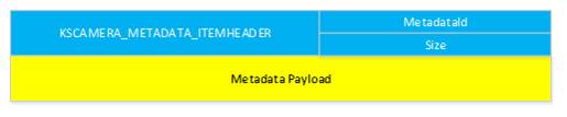
typedef struct tagKSCAMERA_METADATA_ITEMHEADER {
    ULONG MetadataId;
    ULONG Size; // Size of this header + metadata payload following
} KSCAMERA_METADATA_ITEMHEADER, *PKSCAMERA_METADATA_ITEMHEADER;
The MetadataId field is filled by an identifier from the following enum definition that contains well-defined identifiers and custom identifiers (identifiers >= MetadataId_Custom_Start).
typedef enum {
    MetadataId_Standard_Start = 1,
    MetadataId_PhotoConfirmation = MetadataId_Standard_Start,
    MetadataId_UsbVideoHeader,
    MetadataId_CaptureStats,
    MetadataId_CameraExtrinsics,
    MetadataId_CameraIntrinsics,
    MetadataId_FrameIllumination,
    MetadataId_Standard_End = MetadataId_FrameIllumination,
    MetadataId_Custom_Start = 0x80000000,
} KSCAMERA_MetadataId;
The Size field is set to sizeof(KSCAMERA_METADATA_ITEMHEADER) + sizeof(Metadata Payload).
2.2.3.2 Firmware-generated standard-format metadata from USB video frame packets
During a transfer over UVC for frame based video, the video frame is packetized into a series of packets, each preceded by a UVC Payload Header. Each UVC Payload Header is defined by the USB Video Class Driver Frame Based Payload specification:
Payload Header
The following is a description of the payload header format for Frame Based formats.
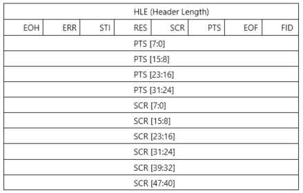
HLE (Header length) field
The header length field specifies the length of the header, in bytes.
Bit field header field
FID: Frame Identifier
- This bit toggles at each frame start boundary and stays constant for the rest of the frame.
EOF: End of Frame
- This bit indicates the end of a video frame and is set in the last video sample belonging to a frame. The use of this bit is an optimization to reduce latency in completion of a frame transfer, and is optional.
PTS: Presentation Time Stamp
- This bit, when set, indicates the presence of a PTS field.
SCR: Source Clock Reference
- This bit, when set, indicates the presence of a SCR field.
RES: Reserved.
- Set to 0.
STI: Still Image
- This bit, when set, identifies a video sample as belonging to a still image.
ERR: Error Bit
- This bit, when set, indicates an error in the device streaming.
EOH: End of Header
- This bit, when set, indicates the end of the BFH fields.
PTS: Presentation Time Stamp, Size: 4 bytes, Value: Number
- The PTS field is present when the PTS bit is set in the BFH[0] field. See Section 2.4.3.3 "Video and Still Image Payload Headers" in the USB Device Class Definition for Video Devices specification.
SCR: Source Clock Reference, Size: 6 bytes, Value: Number
- The SCR field is present when the SCR bit is set in the BFH[0] field. See Section 2.4.3.3 Video and Still Image Payload Headers in the USB Device Class Definition for Video Devices specification.
The HLE field in the existing UVC driver is fixed to either 2 bytes (no PTS/SCR present) or up to 12 bytes (PTS/SCR present). However, the HLE field, being a byte sized field, can potentially specify up to 255 bytes of header data. If both PTS/SCR are present, and the HLE isgreater than 12 bytes, any additional data following the first 12 bytes of the payload header is picked up as standard metadata specific to the video frame when INF entry StandardFormatMetadata<PinIndex> is set.
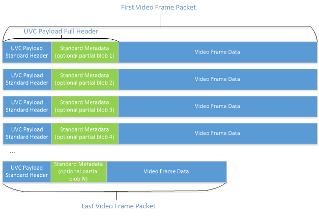
The standard-format metadata (generated by firmware) for a frame is obtained by concatenating the partial blobs found in the video frame packets representing that frame.
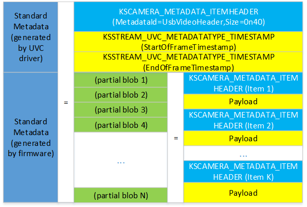
2.2.3.3 Metadata buffer provided to user-mode component
The metadata buffer provided to the user mode component would have a metadata item for the UVC timestamps (generated by UVC driver) followed by firmware-generated metadata items and they're laid out as follows:
2.2.3.4 Metadata format for standard metadata identifiers
The firmware can choose whether or not to produce metadata corresponding to an identifier. If the firmware chooses to produce metadata corresponding to an identifier, then that identifier's metadata shall be present on all frames emitted by the firmware.
2.2.3.4.1 MetadataId_CaptureStats
The metadata format for this identifier is defined by the following structure:
typedef struct tagKSCAMERA_METADATA_CAPTURESTATS {
    KSCAMERA_METADATA_ITEMHEADER Header;
    ULONG Flags;
    ULONG Reserved;
    ULONGLONG ExposureTime;
    ULONGLONG ExposureCompensationFlags;
    LONG ExposureCompensationValue;
    ULONG IsoSpeed;
    ULONG FocusState;
    ULONG LensPosition; // a.k.a Focus
    ULONG WhiteBalance;
    ULONG Flash;
    ULONG FlashPower;
    ULONG ZoomFactor;
    ULONGLONG SceneMode;
    ULONGLONG SensorFramerate;
} KSCAMERA_METADATA_CAPTURESTATS, *PKSCAMERA_METADATA_CAPTURESTATS;
The Flags field indicates which of the later fields in the structure are filled and have valid data. The Flags field shall not vary from frame to frame. Currently, the following flags are defined:
#define KSCAMERA_METADATA_CAPTURESTATS_FLAG_EXPOSURETIME            0x00000001
#define KSCAMERA_METADATA_CAPTURESTATS_FLAG_EXPOSURECOMPENSATION    0x00000002
#define KSCAMERA_METADATA_CAPTURESTATS_FLAG_ISOSPEED                0x00000004
#define KSCAMERA_METADATA_CAPTURESTATS_FLAG_FOCUSSTATE              0x00000008
#define KSCAMERA_METADATA_CAPTURESTATS_FLAG_LENSPOSITION            0x00000010
#define KSCAMERA_METADATA_CAPTURESTATS_FLAG_WHITEBALANCE            0x00000020
#define KSCAMERA_METADATA_CAPTURESTATS_FLAG_FLASH                   0x00000040
#define KSCAMERA_METADATA_CAPTURESTATS_FLAG_FLASHPOWER              0x00000080
#define KSCAMERA_METADATA_CAPTURESTATS_FLAG_ZOOMFACTOR              0x00000100
#define KSCAMERA_METADATA_CAPTURESTATS_FLAG_SCENEMODE               0x00000200
#define KSCAMERA_METADATA_CAPTURESTATS_FLAG_SENSORFRAMERATE         0x00000400
The Reserved field is reserved for future and shall be set to 0.
The ExposureTime field contains the exposure time, in 100 ns, applied to the sensor when the frame was captured. This shows up as attribute MF_CAPTURE_METADATA_EXPOSURE_TIME on the corresponding MF sample.
The ExposureCompensationFlags field contains the EV compensation step (exactly one of the KSCAMERA_EXTENDEDPROP_EVCOMP_XXX step flags shall be set) used to convey the EV Compensation value. The ExposureCompensationValue field contains the EV Compensation value in units of the step applied to the sensor when the frame was captured. These show up as attribute MF_CAPTURE_METADATA_EXPOSURE_COMPENSATION on the corresponding MF sample.
The IsoSpeed field contains the ISO speed value applied to the sensor when the frame was captured. This is unitless. This shows up as attribute MF_CAPTURE_METADATA_ISO_SPEED on the corresponding MF sample.
The FocusState field contains the current focus state that can take one of the values defined in enum KSCAMERA_EXTENDEDPROP_FOCUSSTATE. This shows up as attribute MF_CAPTURE_METADATA_FOCUSSTATE on the corresponding MF sample.
The LensPosition field contains the logical lens position when the frame was captured, which is unitless. This is the same value that can be queried from KSPROPERTY_CAMERACONTROL_EXTENDED_FOCUS in a GET call. This shows up as attribute MF_CAPTURE_METADATA_LENS_POSITION on the corresponding MF sample.
The WhiteBalance field contains the white balance applied to the sensor when the frame was captured, which is a value in Kelvin. This shows up as attribute MF_CAPTURE_METADATA_WHITEBALANCE on the corresponding MF sample.
The Flash field contains a boolean value with 1 meaning flash on, and 0 meaning flash off, when frame was captured. This shows up as attribute MF_CAPTURE_METADATA_FLASH on the corresponding MF sample.
The FlashPower field contains the flash power applied to the frame captured which is a value in the range of [0, 100]. This field should be omitted if the driver doesn't support adjustable power for flash. This shows up as attribute MF_CAPTURE_METADATA_FLASH_POWER on the corresponding MF sample.
The ZoomFactor field contains the zoom value in Q16 format applied to the frame captured. This shows up as attribute MF_CAPTURE_METADATA_ZOOMFACTOR on the corresponding MF sample.
The SceneMode field contains the scene mode applied to the frame captured which is a 64 bit KSCAMERA_EXTENDEDPROP_SCENEMODE_XXX flag. This shows up as attribute MF_CAPTURE_METADATA_SCENE_MODE on the corresponding MF sample.
The SensorFramerate field contains the measured sensor readout rate in hertz when the frame is captured, which consists of a numerator value in the upper 32 bit and a denominator value in the lower 32 bit. This shows up as attribute MF_CAPTURE_METADATA_SENSORFRAMERATE on the corresponding MF sample.
2.2.3.4.2 MetadataId_CameraExtrinsics
The metadata format for this identifier involves the standard KSCAMERA_METADATA_ITEMHEADER followed by a byte-array payload. The payload should align to a MFCameraExtrinsics structure followed by zero or more MFCameraExtrinsic_CalibratedTransform structures. The payload must be 8-byte aligned and all unused bytes shall occur at the end of the payload and be set to 0.
2.2.3.4.3 MetadataId_CameraIntrinsics
The metadata format for this identifier involves the standard KSCAMERA_METADATA_ITEMHEADER followed by a byte-array payload. The payload should align to a MFPinholeCameraIntrinsics structure. The payload must be 8-byte aligned and all unused bytes shall occur at the end of the payload and be set to 0.
2.2.3.4.4 MetadataId_FrameIllumination
The metadata format for this identifier is defined by the following structure:
typedef struct tagKSCAMERA_METADATA_FRAMEILLUMINATION {
    KSCAMERA_METADATA_ITEMHEADER Header;
    ULONG Flags;
    ULONG Reserved;
} KSCAMERA_METADATA_FRAMEILLUMINATION, *PKSCAMERA_METADATA_FRAMEILLUMINATION;
The Flags field indicates information about the captured frame. Currently, the following flags are defined:
#define KSCAMERA_METADATA_FRAMEILLUMINATION_FLAG_ON 0x00000001
If a frame was captured when illumination was on, the flag KSCAMERA_METADATA_FRAMEILLUMINATION_FLAG_ON shall be set. Otherwise, this flag shall not be set.
The Reserved field is reserved for future use and shall be set to 0.
Example:
As an example, a KSCAMERA_METADATA_FRAMEILLUMINATION structure indicating illumination was on would be as follows:
KSCAMERA_METADATA_FRAMEILLUMINATION.Header.MetadataId = MetadataId_FrameIllumination;
KSCAMERA_METADATA_FRAMEILLUMINATION.Header.Size = 16; // 4 ULONG variables in total inside the structure
KSCAMERA_METADATA_FRAMEILLUMINATION.Flags = KSCAMERA_METADATA_FRAMEILLUMINATION_FLAG_ON;
KSCAMERA_METADATA_FRAMEILLUMINATION.Reserved = 0;
2.2.3.4.5 MetadataId_USBVideoHeader
The metadata format for this identifier is defined by a common KSCAMERA_METADATA_ITEMHEADER followed by a KSSTREAM_UVC_METADATA structure:
typedef struct
{
    ULONG       PresentationTimeStamp;
    ULONG       SourceClockReference;
    union
    {
        struct
        {
            USHORT    Counter : 11;
            USHORT  Reserved : 5;
        };
        USHORT    SCRToken;
    };
    USHORT      Reserved0;
    ULONG       Reserved1;
} KSSTREAM_UVC_METADATATYPE_TIMESTAMP, *PKSSTREAM_UVC_METADATATYPE_TIMESTAMP;

typedef struct {
    KSSTREAM_UVC_METADATATYPE_TIMESTAMP StartOfFrameTimestamp;
    KSSTREAM_UVC_METADATATYPE_TIMESTAMP EndOfFrameTimestamp;
} KSSTREAM_UVC_METADATA, *PKSSTREAM_UVC_METADATA;
The StartOfFrameTimestamp and EndOfFrameTimestamp field are the timestamps contained in the UVC headers in the first and last UVC payloads issued by the camera to construct this frame.
This payload shouldn't be sent by a device.
This metadata payload is unique in that it's the only metadata payload generated directly by the USB Video class driver from information obtained from UVC compliant payload headers.
This payload is prepended to the metadata buffer of each frame.
If the device supports standardized metadata, it must include the space needed to store this payload in its buffer requirements as reported by the Metadata control defined in section 2.2.2.9.