Note
Access to this page requires authorization. You can try signing in or changing directories.
Access to this page requires authorization. You can try changing directories.
This section describes the tasks that you must complete before you test an SCSI controller by using the Windows Hardware Lab Kit (Windows HLK):
Hardware Requirements
The following hardware is required to test an ATA/ATAPI controller. You might need additional hardware if the test device offers other features. To determine whether additional hardware requirements apply, see the test description for each test that appears for the device in Windows HLK Studio.
Note
With the exception of the test computer and test controller, all hardware that is involved in the test must already have a logo.
One test computer. The test computer must meet the Windows HLK requirements. For more information, see Windows HLK Prerequisites.
Two identical SCSI controllers (the test devices), unless the test device is an integrated controller.
One PCI-to-PCI bridge adapter, unless any of the following conditions apply:
The RAID controllers cannot fit into PCI bridge adapters. This may occur if the controllers are integrated controllers or if the controllers can only fit into specially designed slots.
The RAID controller is designed and sold only for systems that cannot accept full height PCI-to-PCI bridge adapters, such as blade servers.
You can put one of the RAID controllers into a PCI bus slot that is already behind a PCI bridge.
If the SCSI controller supports RAID, you must have all of the following:
One SCSI JBOD.
One additional SCSI JBOD or three SCSI hard disk drives, unless the test device is an integrated controller.
One optical drive.
If the SCSI controller does not support RAID, you must have all of the following:
Three identical SCSI hard disk drives that have Wide SCSI support, if the test device supports it. The hard disk drives must each have at least 40 gigabytes (GB).
Two SCSI CD drives that have a minimum speed of 8x.
One SCSI removable media drive.
One SCSI tape drive that has Wide SCSI support, if the test device supports it.
One blank tape cartridge.
One bootable controller and hard disk drive (36 GB minimum), if the test device does not support boot.
Note
To certify your product for use on servers, the test computer must support four processors and a minimum of 1 GB of RAM. These system capabilities are required to test the Rebalance, D3 State, and Multiple Processor Group functionality of the device and driver. You do not need a computer that actually has more than 64 processors to test your device. Additionally, the server system(s) being used for device or driver testing must have Server Core installed prior to testing. For more information see Windows Server Installation Options.
If you use a pool of test computers to test devices, at least one computer in the pool must contain four processors and a minimum of 1 GB of RAM. Additionally, that computer must contain the device and the driver that you want to test. If the driver is the same on all the computers in the pool, the system creates a schedule to run against all test computers.
For tests that do not include a driver to test, such as hard disk drive tests, the Windows HLK scheduler constrains the tests that validate the device's and driver's rebalance, D3 state, and multiple processor groups functionality to run on the default test computer. You must manually configure this computer to have multiple processor groups. The default computer is the first test computer in the list. Test personnel must make sure that the first test computer in the list meets the minimum hardware requirements.
Note
Except for para-virtualization drivers (as defined by the WHCP Policies and Processes document), you may not use any form of virtualization when you test physical devices and their associated drivers for server certification or signature. All virtualization products do not support the underlying functionality that is required to pass the tests that relate to multiple processor groups, device power management, device PCI functionality, and other tests.
Note
Multiple Processor Groups Setting You must set the value for the processor group size for Hardware Lab Kit testing of Windows Server 2008 R2 and later device drivers for certification. This is done by running bcdedit in an elevated command prompt window, using the /set option.
The commands for adding the group settings and restarting are as follows:
bcdedit.exe /set groupsize 2
bcdedit.exe /set groupaware on
shutdown.exe -r -t 0 -f
The commands for removing the group settings and rebooting are as follows:
bcdedit.exe /deletevalue groupsize
bcdedit.exe /deletevalue groupaware
shutdown.exe -r -t 0 -f
Note
Code Integrity Setting
The Virtualization Based Security feature (VBS) of Windows Server 2016 must be enabled using Server Manager first.
Once that has occurred, the following Registry key must be created and set:
HKLM\System\CurrentControlSet\Control\DeviceGuard
HypervisorEnforcedCodeIntegrity:REG_DWORD
0 or 1 (disabled, enabled)
Software Requirements
The following software is required to test an SCSI controller:
The drivers for the test controllers.
The latest Windows HLK filters or updates.
Windows symbol files. These are available from the Symbol Files website.
The current release of the Windows Driver Kit (WDK).
Test Computer Configuration
There are three possible configurations for testing SCSI controllers:
If the test device is an add-in controller that supports RAID, use the Add-in RAID controller test configuration.
If the test device is an integrated controller that supports RAID, use the Integrated RAID controller test configuration.
If the test device does not support RAID, use the Non-RAID controller test configuration.
Before you test an SCSI controller in any of the three usage scenarios, make sure that the test computer is in the ready state. If a test requires parameters to be set before it is run, a dialog box appears for that test. Review the specific test topic for more information.
Some Windows HLK tests require user intervention. When you run tests for a submission, it is a best practice to run the automated tests in a block separately from manual tests. This prevents a manual test from interrupting completion of an automated test.
Add-in RAID controller test configuration
To configure the test computer to test an SCSI controller in an add-in RAID configuration, follow these steps:
When the test computer is turned off, complete the following assembly steps:
Install a boot-capable controller (not the test device) and hard disk drive, if the test devices do not support boot.
Install one test controller (Controller 1).
Install a PCI-to-PCI bridge, unless any of the following conditions apply:
The RAID controllers cannot fit into PCI bridge adapters. This may occur if the controllers are integrated controllers or if the controllers can only fit into specially designed slots.
The RAID controller is designed and sold only for systems that cannot accept full height PCI-to-PCI bridge adapters, such as blade servers.
You can put one of the RAID controllers into a PCI bus slot that is already behind a PCI bridge.
Install a second, duplicate test controller (Controller 2) into the PCI-to-PCI bridge card (or in the PCI bridge if the bridge card is not required).
Attach the disks to the test devices according to the following table:
Controller type Controller 1 Controller 2 SCSI RAID
One SCSI JBOD
One SCSI JBOD
Attach an optical drive to the system, if one is not already attached.
Turn on the test computer.
Set the system BIOS to support the S3 state.
Create one 60-GB RAID array on Controller 1 and two 60-GB RAID arrays on Controller 2. The RAID array on Controller 1 is RAID Array 1, and the RAID arrays on Controller 2 are RAID Array 2 and RAID Array 3.
Configure the RAID arrays according to the following table:
RAID levels that the test device supports RAID level for RAID Array 1 RAID level for RAID Array 2 RAID level for RAID Array 3 0 only
0
0
0
1 only
1
1
1
5 only
5
5
5
0 and 1 only
1
9
0
0 and 5 only
5
9
0
1 and 5 only
5
1
1
0, 1, and 10
10
1
0
0, 1, and 5
5
1
0
0, 1, 10, and 5
5
10
0
Turn on the test computer, install the appropriate Windows operating system on disk 1 by using a newly created NTFS partition that has at least 36 GB of disk space, and then configure the computer for your test network. The test network is the network that contains the Windows HLK Studio and Windows HLK Controller. If the test controller is not bootable, install a separate hard disk drive on a bootable controller.
If you have to install the manufacturer-supplied device driver on the test computer, do this now.
Start Windows on the test computer.
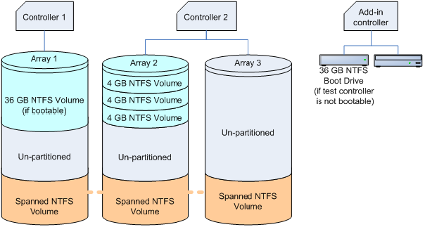
Create three 4-GB partitions on RAID Array 2.
If you are testing by using a client operating system, create a 4-GB NTFS spanned volume that uses unallocated space on RAID Array 1, RAID Array 2, and RAID Array 3, as the following diagram shows.
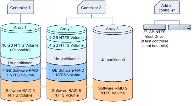
If you are testing by using a server operating system, do the following:
Create a software RAID 1 mirror from one of the NTFS partitions on RAID Array 2 to the unallocated space on RAID Array 1
Create a 4-GB NTFS software RAID 5 array that uses unallocated space on RAID Array 1, RAID Array 2, and RAID Array 3, as the following diagram shows.
To set the system page file and enable crashdump, follow these steps:
Click the Start button, right-click My Computer, and then click Properties.
Click the General tab, and then note the amount of RAM that the computer contains.
Click the Advanced tab (or click Advanced system settings in the left pane for Windows Vista, Windows 7, Windows 8, Windows Server 2008, Windows Server 2008 R2 or Windows Server 2012), and then, in the Performance area, click Settings.
Note
If you are prompted to enter administrative credentials or allow the action, enter the credentials or allow the action.
Click the Advanced tab, and then, in the Virtual Memory area, click Change.
Select Custom Size, and then enter a number in the Initial size (MB) box that is larger than the size of RAM that you noted in step b.
In the Maximum size (MB) text box, enter a maximum size value that is larger than the initial size that you entered in the Initial size (MB) box. (The maximum size is typically 1.5 to 2 times the initial size.)
Click Set, and then click OK two times.
Click OK, and then restart the computer to update the page file size.
Verify that the storage array is accessible from the test computer.
Copy the Windows symbol files to %SystemDrive%\Symbols.
Install the Windows HLK client application on the test computer.
Use Windows HLK Studio to create a computer pool, and then move the test computer to that pool.
Integrated RAID controller test configuration
To configure the test computer to test an SCSI controller in an integrated RAID configuration, follow these steps:
When the test computer is turned off, complete the following assembly steps:
Install a boot-capable controller (not the test device) and hard disk drive, if the test devices do not support boot.
Attach the disks to the integrated test controller (Controller 1) according to the following table:
Controller type Controller 1 SCSI RAID
One SCSI JBOD or three SCSI hard disk drives, and one SCSI optical drive (if supported)
Attach an optical drive to the system, if one is not already attached.
Turn on the test computer.
Set the system BIOS to support the S3 state.
Create two 60-GB RAID arrays on Controller 1.
If the controller does not support a configuration that includes two arrays, use a non-RAID disk instead of Array 2 for these procedures. For SCSI, create a third 60-GB RAID array (using any supported RAID level).
The RAID arrays on Controller 1 are RAID Array 1 and RAID Array 2.
Configure the RAID arrays according to the following table:
RAID levels that the test device supports RAID level for RAID Array 1 RAID level for RAID Array 2 0 only
0
0
1 only
1
1
5 only
5
5 or Non-RAID disk
0 and 1 only
1
0
0 and 5 only
5
0 or Non-RAID disk
1 and 5 only
5
1or Non-RAID disk
0, 1, and 10
10
1 or Non-RAID disk
0, 1, and 5
5
0 or Non-RAID disk
0, 1, 10, and 5
5
10 or Non-RAID disk
Install the appropriate Windows operating system, and then configure the computer for your test network. The test network is the network that contains the Windows HLK Studio and Windows HLK Controller.Windows HLK Studio and Windows HLK Controller. If the test controller is not bootable, install Windows to a separate hard disk drive on a bootable controller.
If it is necessary, install any drivers that a manufacturer supplies that the devices in the test system require.
Start Windows on the test computer.
Use the Windows Disk Management utility to configure all of the disks to be dynamic.
Create three 4-GB NTFS partitions on RAID Array 2.
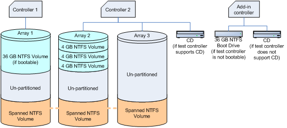
If you are testing by using a client operating system, create a 4-GB NTFS spanned volume that uses unallocated space on RAID Array 1, RAID Array 2, and Array 3 as the following diagram shows.
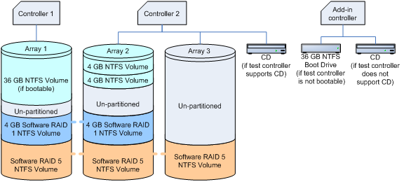
If you are testing by using a server operating system:
Create a software RAID 1 mirror from one of the NTFS partitions on RAID Array 1 to the unallocated space on RAID Array 2, as the following diagram shows.
Create a software NTFS RAID 5 array that uses unallocated space on RAID Array 1, RAID Array 2, and RAID Array 3, as the following diagram shows.
To set the system page file and enable crashdump, follow these steps:
Click the Start button, right-click My Computer, and then click Properties.
Click the General tab, and then note the amount of RAM that the computer contains.
Click the Advanced tab (or click Advanced system settings in the left pane for Windows Vista, Windows 7, Windows 8, Windows Server 2008, Windows Server 2008 R2 or Windows Server 2012), and then, in the Performance area, click Settings.
Note
If you are prompted to enter administrative credentials or allow the action, enter the credentials or allow the action.
Click the Advanced tab, and then, in the Virtual Memory area, click Change.
Select Custom Size, and then enter a number in the Initial size (MB) box that is larger than the size of RAM that you noted in step b.
In the Maximum size (MB) text box, enter a maximum size value that is larger than the initial size that you entered in the Initial size (MB) box. (The maximum size is typically 1.5 to 2 times the initial size.)
Click Set, and then click OK two times.
Click OK, and then restart the computer to update the page file size.
Verify that the storage array is accessible from the test computer.
Copy the Windows symbol files to %SystemDrive%\Symbols.
Install the Windows HLK client application on the test computer.
Use Windows HLK Studio to create a computer pool, and then move the test computer to that pool.
Non-RAID controller test configuration
To configure the test computer to test an SCSI controller in a non-RAID configuration, follow these steps:
When the test computer is turned off, complete the following assembly steps:
Install a boot-capable controller (not the test device) and hard disk drive if the test devices do not support boot.
Install the test device (Controller 1).
Install a PCI-to-PCI bridge, unless any of the following conditions apply:
The RAID controllers cannot fit into PCI bridge adapters. This may occur if the controllers are integrated controllers or if the controllers can only fit into specially designed slots.
The RAID controller is designed and sold only for systems that cannot accept full height PCI-to-PCI bridge adapters, such as blade servers.
You can put one of the RAID controllers into a PCI bus slot that is already behind a PCI bridge.
Install a second, duplicate test controller (Controller 2) in the PCI-to-PCI bridge card (or in the PCI bridge if the bridge card is not required).
Attach the disks to the test devices according to the following table.
Controller type Controller 1 Controller 2 SCSI add-in controllers
SCSI HDD (Disk 1)
SCSI optical drive
SCSI tape drive
SCSI removable media drive
SCSI HDD (Disk 2)
SCSI optical drive
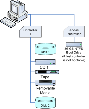
SCSI integrated controllers
NoteSee the SCSI add-in controllers configuration diagram below.
SCSI HDD (Disk 1)
SCSI optical drive
SCSI tape drive
SCSI removable media drive
SCSI HDD (Disk 2)
N/A
For SCSI add-in controllers, configure the hardware as described in the following diagram:
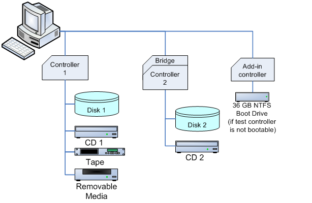
For SCSI integrated controllers, configure the hardware as described in the following diagram:
6. Attach an optical drive to the system, if one is not already attached.
Turn on the test computer.
Set the system BIOS to support the S3 state.
Install the appropriate Windows operating system, and then configure the computer for your test network. The test network is the network that contains the Windows HLK Studio and Windows HLK Controller.
If you have to install the manufacturer-supplied device driver on the test computer, do this now.
Create three 4-GB partitions on Disk 2.
Use the following procedure to set the system page file and enable crashdump:
Click the Start button, right-click My Computer, and then click Properties.
Click the General tab, and then note the amount of RAM that the computer contains.
Click the Advanced tab (or click Advanced system settings in the left pane for Windows Vista, Windows 7, Windows 8, Windows Server 2008, Windows Server 2008 R2 or Windows Server 2012), and then, in the Performance area, click Settings.
Note
If you are prompted to enter administrative credentials or allow the action, enter the credentials or allow the action.
Click the Advanced tab, and then, in the Virtual Memory area, click Change.
Select Custom Size, and then enter a number in the Initial size (MB) box that is larger than the size of RAM that you noted in step b.
In the Maximum size (MB) text box, enter a maximum size value that is larger than the initial size that you entered in the Initial size (MB) box. (The maximum size is typically 1.5 to 2 times the initial size.)
Click Set, and then click OK two times.
Click OK, and then restart the computer to update the page file size.
Verify that the storage array is accessible from the test computer.
Copy the Windows symbol files to %SystemDrive%\Symbols.
Install the Windows HLK client application on the test computer.
Use Windows HLK Studio to create a computer pool, and then move the test computer to that pool.
Warning
When testing storage devices, we strongly recommend that you complete all Device Fundamentals tests before starting storage tests. Storage tests will reconfigure your test device, leaving the device in a state unsuitable to support Device Fundamentals tests. The following configurations provide steps to create volume on the storage test device. This is important to complete the Device Fundamental part of testing (DevFund).