Hyper-V Virtual Fibre Channel
Hyper-V provides Fibre Channel ports within guest operating systems (OSes) that let you connect to Fibre Channel directly from your virtual machines (VMs). This feature lets you virtualize workloads that use direct access to Fibre Channel storage, cluster guests over Fibre Channel, and gives you more storage options for servers hosted in your virtualization infrastructure. This article gives a brief overview of Fibre Channel on Hyper-V so you can understand how to implement the Virtual Fibre Channel into your Hyper-V planning.
Prerequisites
In order to use Virtual Fibre Channel on Hyper-V, your deployment must have the following:
One or more installations of Windows Server 2012 or later with the Hyper-V role installed.
A device with one or more Fibre Channel host bus adapters (HBAs) and an updated HBA driver that supports Virtual Fibre Channel.
HBA ports must also have a Fibre Channel topography that can support N_Port ID Virtualization (NPIV), a maximum transfer size of at least 0.5 MB, and data transfers of at least 128 physical pages.
The maximum transfer length of the adapter determines the LUN limit. For example, a maximum transfer length of 512k allows about 2,250 LUNs. You need to configure your LUNs and multi-storage paths to maintain these limits.
An NPIV-enabled Storage Area Network (SAN).
VMs that use Windows Server 2012 or later as their guest OS and can support virtual Fibre Channel adapters.
Storage accessible through Virtual Fibre Channel support devices that present logical units. Virtual Fibre Channel logical units can't be used as boot media.
How Virtual Fibre Channel works
Virtual Fibre Channel for Hyper-V provides the guest OS with unmediated access to a SAN by using a standard World Wide Name (WWN) associated with a virtual machine. Hyper-V users can use Fibre Channel SANs to virtualize workloads that require direct access to SAN logical unit numbers (LUNs). Fibre Channel SANs also let you operate in new scenarios, such as running failover clustering inside the guest OS of a VM connected to shared Fibre Channel storage.
Physical deployments use the advanced storage functionality of mid-range and high-end storage arrays to offload certain management tasks from hosts to the Windows software virtual hard disk stack. In virtualized deployments, Virtual Fibre Channel plays a similar role, letting you use your SAN's functionality directly from Hyper-V VMs to offload functionality. For example, when you use Hyper-V to take a snapshot of a LUN, you can offload storage functionality on the SAN hardware by using a hardware Volume Shadow Copy Service (VSS) provider from within a Hyper-V VM.
The following sections explain which Virtual Fibre Channel features help it offload management and storage tasks.
NPIV support
Virtual Fibre Channel for Hyper-V guests uses the existing N_Port ID Virtualization (NPIV) T11 standard to map multiple virtual N_Port IDs to a single physical Fibre Channel N_port. A new NPIV port is created on the host every time you start a VM configured with a virtual HBA. When the VM stops running on the host, the system removes the NPIV port. You should configure any HBA ports that you use for Virtual Fibre Channel in a Fibre Channel topology that supports NPIV, and your SAN should also support NPIV ports.
Virtual SAN support
A virtual SAN defines a named group of physical Fibre Channel ports connected to the same physical SAN. Hyper-V lets you define virtual SANs on the host in scenarios where you connect a single Hyper-V host to different SANs through many Fibre Channel ports.
For example, if a Hyper-V host is connected to a production SAN and a test SAN, then the host is connected to each SAN through two physical Fibre Channel ports. In this scenario, you can configure two virtual SANs. The virtual production SAN has the two physical Fibre Channel ports connected to the physical production SAN. The virtual test SAN has two physical Fibre Channel ports connected to the test SAN. You can use the same technique to name two different paths to the same storage target.
You can configure up to four virtual Fibre Channel adapters on a VM and associate each one with a virtual SAN. Each virtual Fibre Channel adapter connects with one WWN address, and you can set each WWN address automatically or manually. However, in live migration scenarios, two WWN addresses are assigned to each adapter.
Live migration
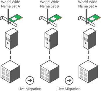
To support live migration of virtual machines across Hyper-V hosts while maintaining Fibre Channel connectivity, two WWNs are configured for each virtual Fibre Channel adapter, as shown in the following diagram. Hyper-V automatically alternates between the Set A and Set B WWN addresses during a live migration. This ensures that all LUNs are available on the destination host before the migration and that no downtime occurs during the migration.
Tape library support
Windows Server only supports virtual tape libraries configured with virtual Fibre Channel adapters when using System Center Data Protection Manager 2012 R2 U3 or later with certified hardware. You can check if your virtual Fibre Channel adapter supports a tape library by contacting the tape library hardware vendor. You can also check compatibility by running the Data Protection Management (DPM) Tape Library Compatibility Test tool on the virtual tape library in a guest VM. For more information about the DPM Tape Library Compatibility Test, see Verify tape library compatibility.
MPIO functionality
Hyper-V in Windows Server can use the multipath I/O (MPIO) functionality to ensure continuous connectivity to Fibre Channel storage from within a VM. You can use MPIO functionality with Fibre Channel in the following ways:
Use MPIO for host access. To use this functionality, you install multiple Fibre Channel ports on the host, then use MPIO to provide highly available connectivity to the LUNs the host can access.
Virtualize workloads that use MPIO. To use this functionality, configure multiple virtual Fibre Channel adapters inside a VM, then use a separate copy of MPIO within the VM operating system to connect to the LUNs that the VM can access. This configuration can coexist with a host MPIO setup.
Use different device-specific modules (DSMs) for the host or each VM. This approach allows live migration of the virtual machine configuration, including DSM, connectivity between hosts, and compatibility with existing server configurations and DSMs.
Note
Live migration scenarios where the guest VM uses MPIO don't support Asymmetric Logical Unit Assignment (ALUA).
Related content
Feedback
Coming soon: Throughout 2024 we will be phasing out GitHub Issues as the feedback mechanism for content and replacing it with a new feedback system. For more information see: https://aka.ms/ContentUserFeedback.
Submit and view feedback for